Week 9 - Project 1 - Door Trim Lower with Engineering Features
DOOR TRIM LOWER
Aim:
To Create the Door trim lower component through the given Class-A surface.
Objectives:
• Creation of Tooling axis with appropriate draft angle.
• Creation of other surfaces (eg, B and C surfaces) for creating a solid component.
• Perform Draft analysis on Class A surface and Solid model hence created.
Procedure:
The below image shows the given class A surface for which a solid model is to be created
...
Tooling axis creation:
It is defined as the direction in which the mould/core and cavity open. Selection of the direction of the tooling axis depends on the ease at which components can be easily ejected.
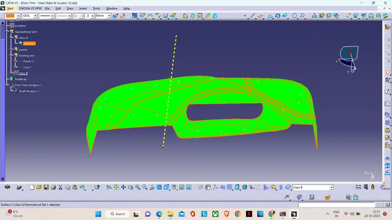
By analysing the component the most easily ejectable direction is somewhere close to the Z direction. Therefore by using the first method we have created a point on the surface and line through it in the direction of Y component,we have created tooling axis.
After the creation of tooling axis we have done a draft analysis to which it has cleared the minimum draft angle. Below is the image for reference
 .
.
Class B surface
We'll start the procedure by creating an offset for the entire Class A Surface at a distance of 2.5mm as that is the desired thickness for our final plastic component.
As this is a complex surface hence the offset will fail to offset every element according to our necessity. It'll select some sub-elements that belong to the filleted regions by themselves that we have to remove to get the rest of the surface that is offsetted.
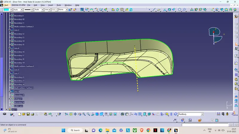
Now, we're going to fix these patches by recreating these sub-elements using various tools such as Extract, Untrim, Extrapolate, Multi-Sections Surface, Trim, etc. Below is the final Class B surface.
 .
.
Class C surface
We'll create the Class C Surface with respect to the Class A Surface and provide draft angles to those surfaces that are parallel to the Main Tooling Axis. Surfaces at the bottom won't be needing any draft angle as they'll get cleared by the core itself. To create the Class C Surface we have to use various commands such as Sweep with Reference Surface and With Draft-Direction depending upon the necessity and at places where it'll be difficult for us to create a surface using Sweep, we'll use Multi-Sections Surface to create those surfaces.
Finally after creating all the three surfaces we will be joining it together and After that, we've to trim these joined surfaces with the Class B Surface but before that, we'll create an intersection between these two surfaces and see whether they're feasible to be trimmed with one another. We'll extrapolate those regions where they aren't intersecting and use the intersection command again to inspect whether the intersection is successful or not. When we'll obtain a complete intersection between these two surfaces we'll trim them together to obtain the final closed body as shown below:
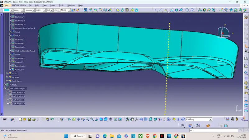 .
.
Finally, we'll go to the Part Workbench and use the option 'Closed Surface' from the 'Surface-based Features' toolbar to convert the final trimmed body into a solid body as shown below:
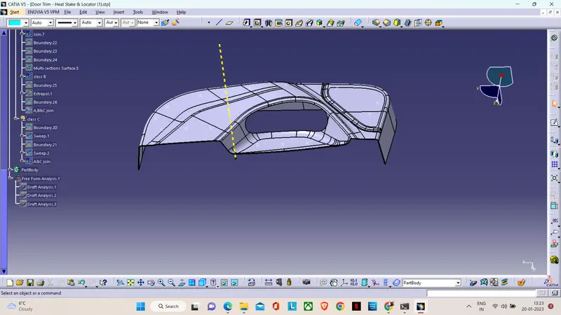 .
.
We'll click on the 'Draft Analysis' under the 'Analysis' Toolbar in the Part Workbench.
We'll drag the compass and place the compass on the Main Tooling-Axis.
Then, we'll select 'Show or Hide the Color Scale' under 'Display' and define our Draft-Angle as 3-Degrees.
After that, we'll click the surface of the Final Part the results of which are shown below:
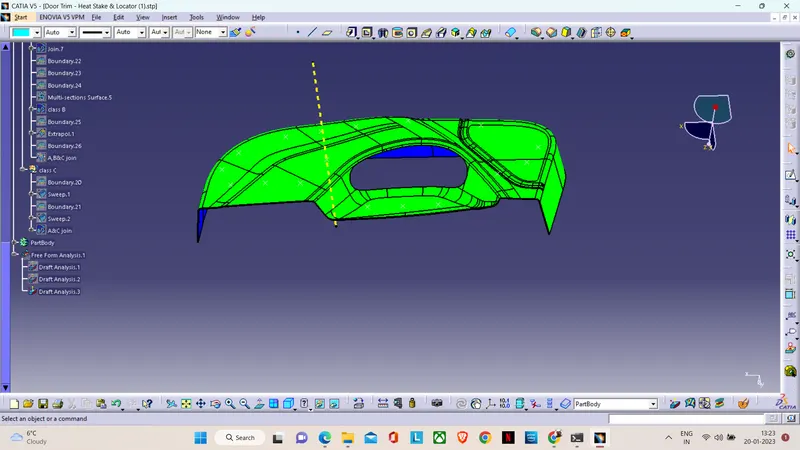 .
.
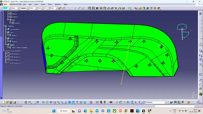
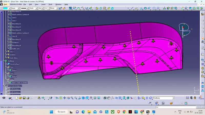
And finally we will be creating the attachment features such as Locators and heatstakes with the help of design rules in the part-workbench. After creation of the skteches we will be padding it and translating it to each point by using point-point translation. Using a boolean operations after creating the solid attachement features we will be joining it to the main body. Below are the images of the solid body with attachement features with and without draft analysis: