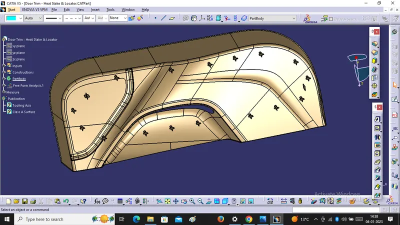
Week 9 - Project 1 - Door Trim Lower with Engineering Features
Design Procedure For Door Trim Lower with Engineering Features :-
Objective:- To Create B&C Surface from the given Class A Surface and after that we will Join them together and Create a Close Surface. For that we have to use Offset, Multi Extract, Extrapolation, Trim, Join & Swip Commands.
Step1.
We have to create Tooling Axis For Given Class A Surface. For that We will Extract One face, Create One Point and Line Normal to Surface. After that We Will get Tooling Axis.
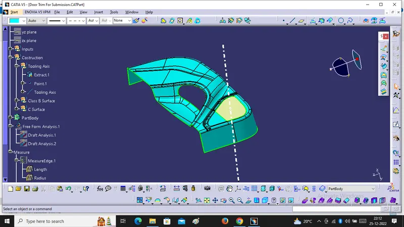
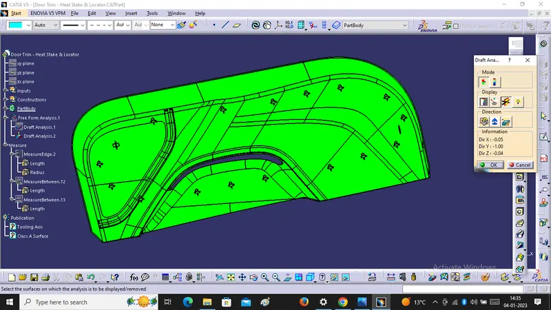
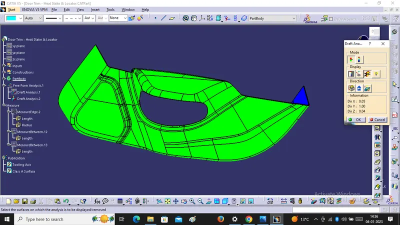
2. After Creation Of Tooling Axis We have to do Draft Analysis With given ClassA Surface at 3 Degree. If the Draft Analysis is Green then Our Tooling Axis is Correct.
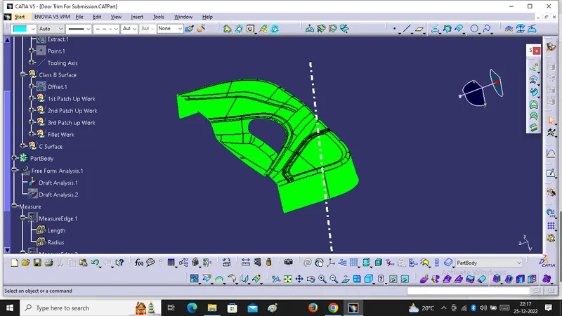
For B Surface Creation
We have to Offset the given class A Surface for 2.5mm in Inside direction, after that we will get the Same Surface as given to class A Surface. But Some patches area available On it. So, We will work On this Area.The Green Colour Inside Lines is showing Patch up Area.
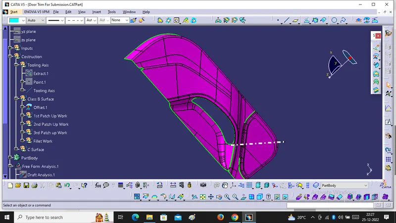
Repairing Work for 1st Patch Area :-
For that We have to Use Multiple Extract, Extrapolation, Split, Trim & Join.
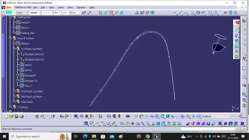
1. Mutiple Extract 5 &6
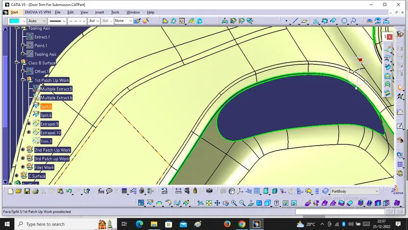
2. Split 5 & 6
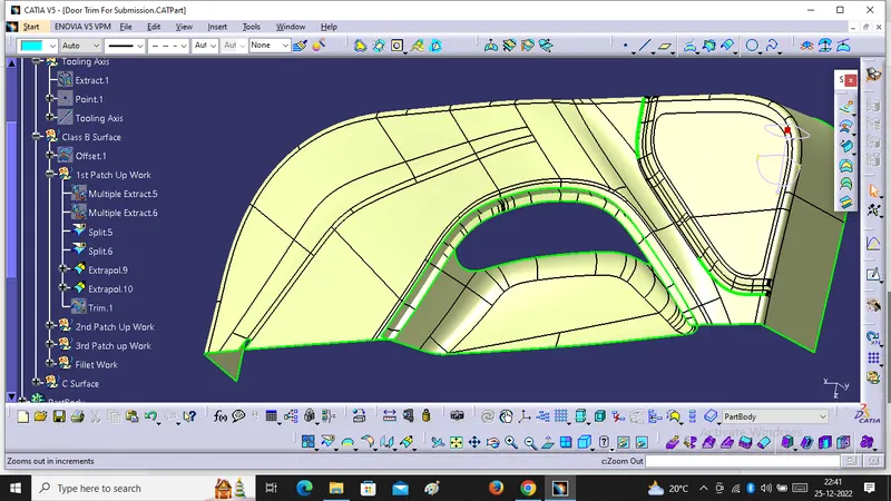
3. Extrapolation 9&10 of 11mm With Tangent Contunity
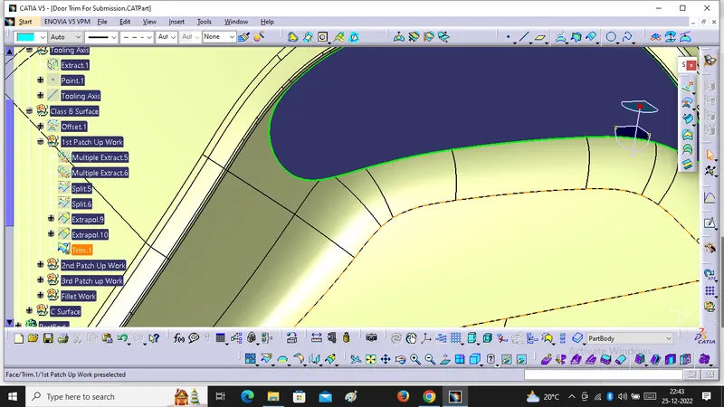
After that We Will Use Trim and Get Removal of 1 st Patch Up Area.
Repairing Work for 2nd Patch Area :-
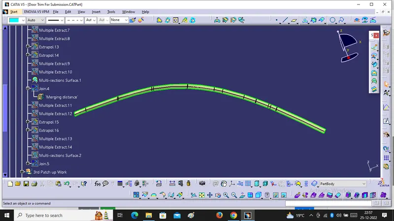
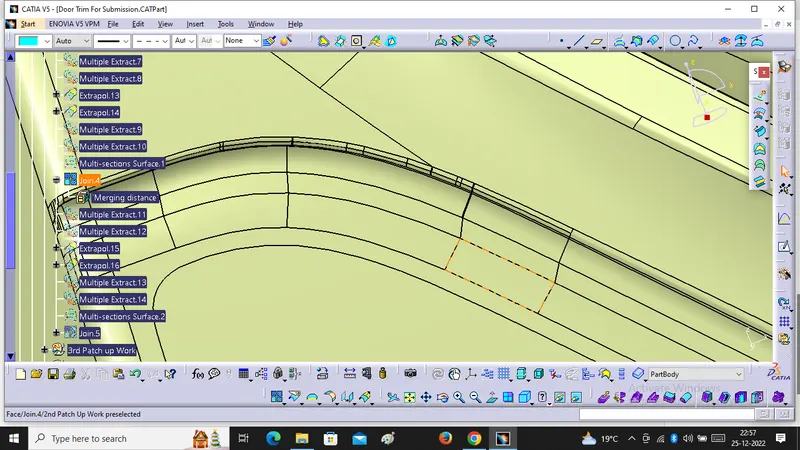
For Repairing of 2nd Patch Up Area We have to Use Multiple Extract, Extrapolation, Join, Multisection Surface. we will use first Multi Extract to separate the green colour Edges after that We will Extrapolate them and Create Multi Section Surface after that We Will Join it together.
Repairing Work for 3rd Patch Area :-
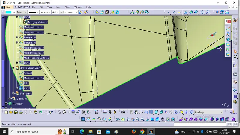
For Repairing 3rd Patch Up Area We Will Use Spline, MultiExtract, Fill & Join. First We Will Create Spline after that Extract Green Edges In Two Parts, after that We Will Use Fill Command to Fill the Gaps. After that we will Join all Surface Together.
Edge Fillet
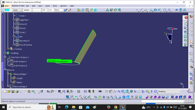
We will use Edge Fillet for the B surface, for that We will Extract One Surface from Class A Surface and Create One Point On Edges and Create Circle of Three Point after that we will Measure Circle Radius and give Fillet to B Surface with Decresing Radius 2.5mm.
Final B Surface
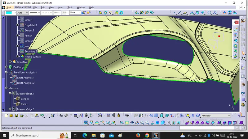
For C Surface Creation
For C Surface Creation We will Use Boundary & Sweep. First We take Boundary From Class A Surface after that We Use Sweep With Refrerence Surface and giving 90 Degree angle and 5mm length we will get Final C Surface.
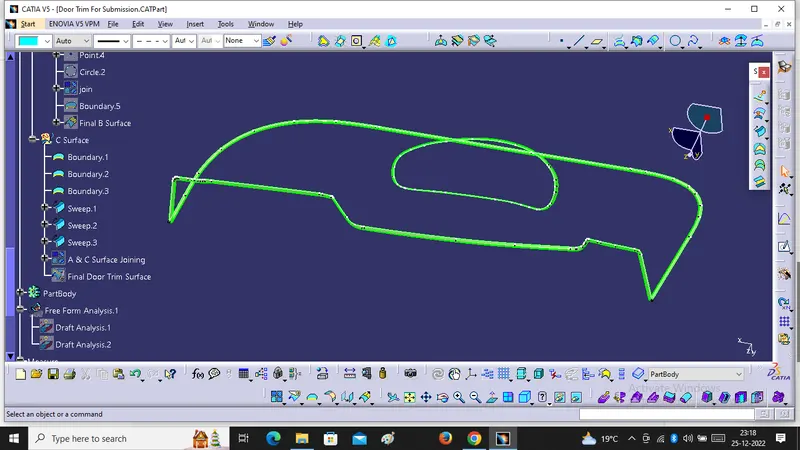
A & C Surface Joining :
We Will Join A Surface With C Surface.
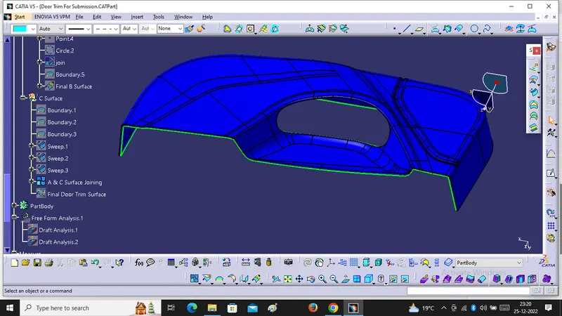
After that We will Trim A&C Surface Join with B Surface. And we will get final Surface.
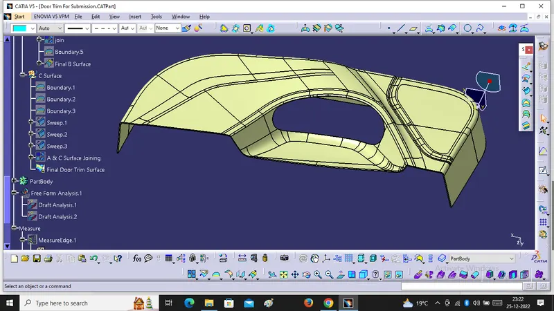
Close Surface
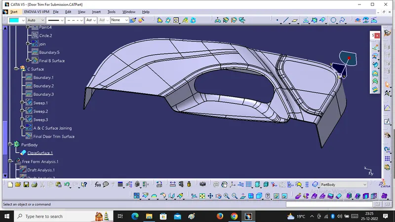
For close surface we have to go in part design after that we will use close surface for final trimed surface.
Heat Stakes Creation -:
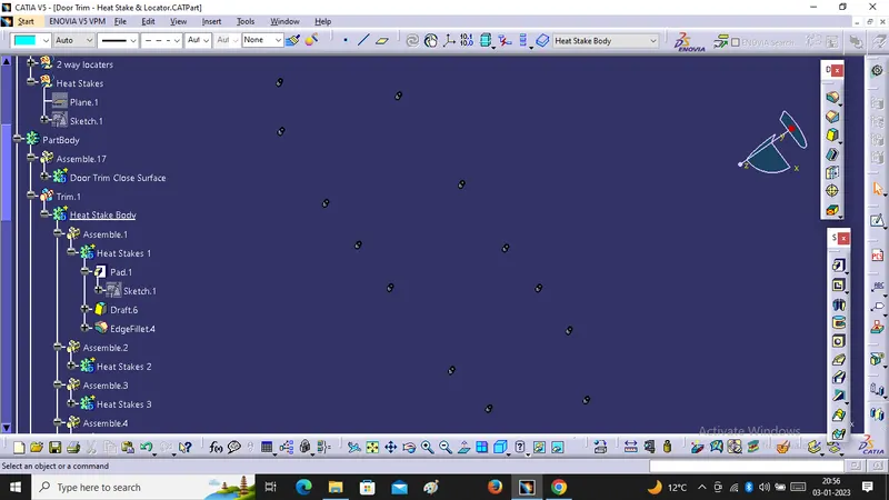
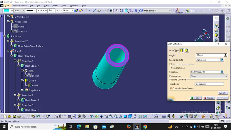
For Heat Stakes Creation We have to take one given Point On Surface, and create One plane On it. and Sketch On it Two Circle after that Paid it. Give draft angle of 0.5 deg and minimum fillet value of 0.30mm. After that copy it and paste it with Special features with link and Translate it on all given Point by point to point method . We will get 16 Heat stakes . After that We will take One body and Assemble it together after that we will unitrim with Main Body.
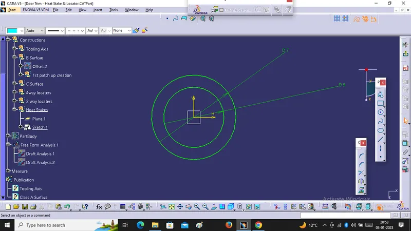
Transltaion
Draft Angle
Edge Fillet
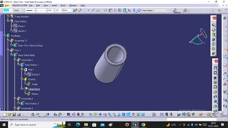
The Height of the Heat Stakes Should be at least 5mm less than the 4 way & 2 Way locators.
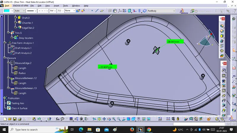
Ribs Creation :-
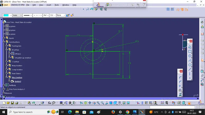
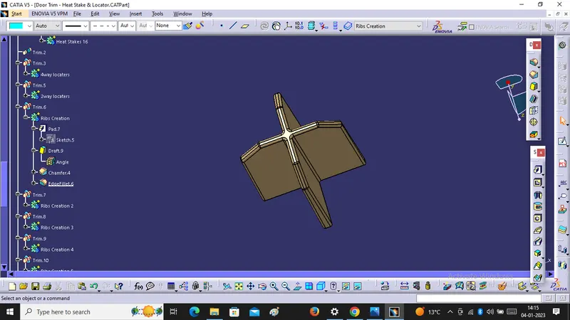
We have to first create Positioned Sketch, Paid it, Drafted it for 0.5deg , chamfer it for 3mm 45deg , filleted it 0.30mm and Translate it on all given points after that We will do unitrim with Main Body and get Ribs.
4 way & 2 way Locators -:
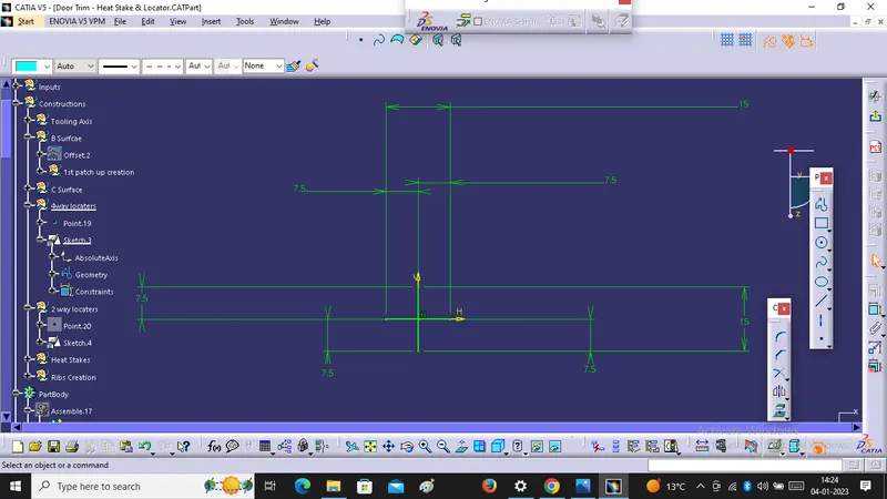
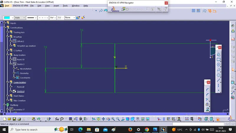
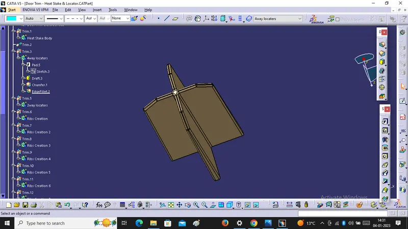
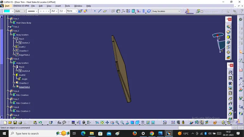
First We have to Create One point and Use the Same Plane create Sketch On it, after that Pad it , Draft it for 0.5 deg with Tooling Axis, Chamfer it for 3mm and 45 deg, give fillet of 0.30mm for all sides . After that Trim it With Main Body.
Draft Analysis For Final Model :-
Final Model :-