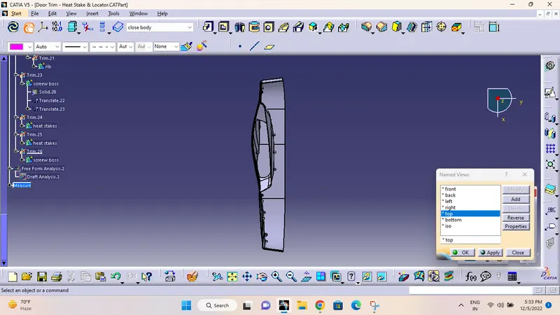
Week 9 - Project 1 - Door Trim Lower with Engineering Features
Detailed Report
Hello this is Mohit Srivastava.
This is the Detailed Report of Door Trim Lower Plastic Component. In which we just talk about How to make (Tooling Axis, Class B Surface, Class C Surface, Heat Stakes and also Locator.)
Bisecting Method
Bisecting Method is the one of the method of making of Tooling Axis. This is the one of the most common method of making Tooling Axis.
- In this method firstly we have to make a Extract of a plane surface.
- After Extract I have to take a Point on a Extract Surface and make a Dummy Axis with reference to direction.
- After this make a Intersection of a Class A Surface.
- And make Two Line on a Intersection Area with point to point reference and make sure that the Line is not perpendicular to Tooling Axis
- And after this Select a Line command and choose a Bisecting Line. And make a Bisecting line with reference that Two line which we make on a Intersection Surface and also select a point of Dummy Axis.
- And Finally Tooling Axis Made.
BUT IN THIS PROJECT WE ARE NOT MAKING TOOLING AXIS WITH BISECTING METHOD BECAUSE THERE IS NO PLANE SURFACE IN THIS CLASS A SURFACE THERE ARE MANY IRREGULAR SURFACE AND FILLET ARE AVAILABLE.
SO WE ARE USING A ANOTHER METHOD WHIS IS ALSO MOSTLY USE IN INDUSTRY NORMAL TO SURFACE
Tooling Axis
- Firstly I just take a Extract on a Plane Surface.
- After Extract I have to take a Point on a Extract Surface and make Tooling axis Line with reference to direction.
- And Finally Tooling Axis Made.
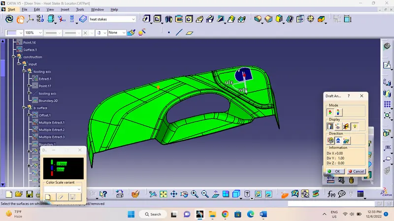
Draft Analysis
Now we have to make draft analysis of a class A surface and check the component.
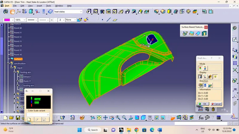
Class B Surface
- Firstly we have to make offset a Class A Surface of a 2.5mm.
And after a offset we just saw that there is some patches open and can also say that some open boundary are there.
- So I make a multiple extract of 4 area.
- And after multiple extract of 4 area I just Extrapolate all 4 area.
- And after extrapolate just trim the all 4 extrapolate area with each other
- And also there is one small open patches available which we filled with the help of multi-sections surface
- And now Class B surface is made.
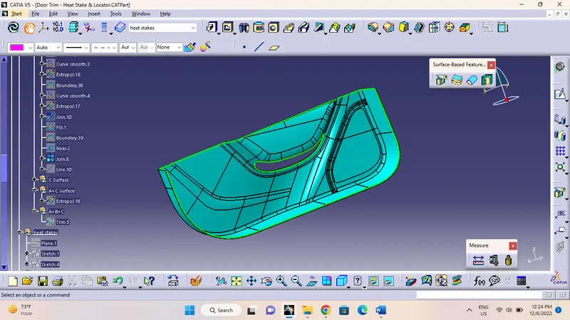
Class C Surface
For making of Class C Surface we use sweep commend where we use 2 option with reference surface or with draft direction
- Firstly we make boundary on a Class A Surface In a 2 step and make a Class C Surface in a 2 step for making accurate or proper.
- After this select the 1 boundary and sweep it with reference to surface.
- And after this select the 2 boundary and sweep it also
- Make sure that the sweep length should be minimum according to the thickness of the component Like 3mm.
- After sweep extrapolate the 4 edges of both sweeps. And trim them to join.
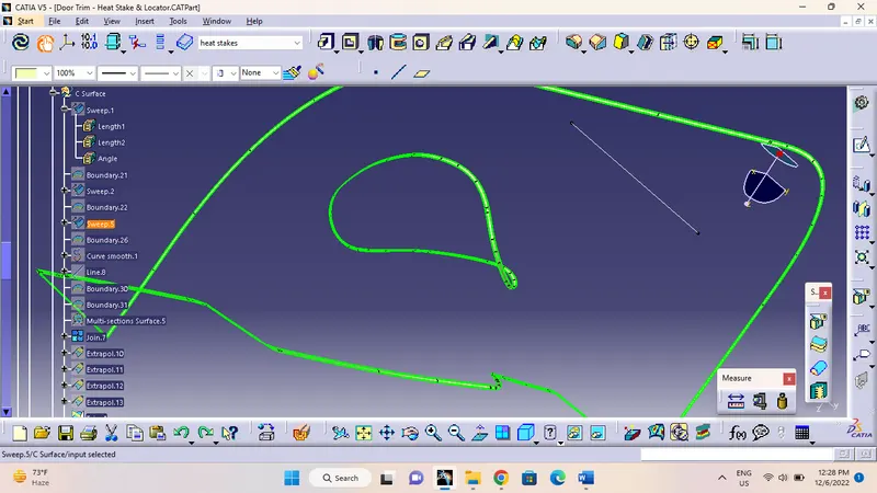
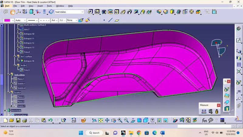
A+C Surface
- For making a A+C Surface just use join commend and select the Class A Surface and Class C Surface.
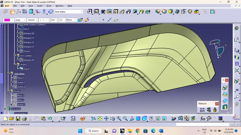
A+B+C Surface
- For making a A+B+C Surface just use trim commend and select A+C Surface and B Surface and trim it.
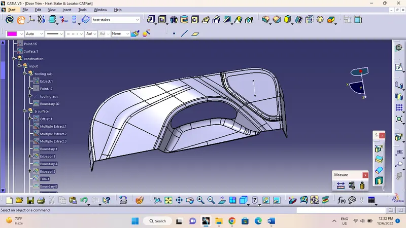
Close Surface
- For making a Close Surface we go on a part workbench and use close surface which is inside in surface-based
- Define a body and select a close surface commend.
- And close surface is become
Draft Analysis
Now we have to make draft analysis and check the component draft angle is ok or not according to industry standard.
Heat Stakes
Firstly make sure that we have to make that locator on a location which is given in the Class A Surface.
- Firstly we make a plane on a point which is given in a Class A Surface with reference to tooling axis.
- And make a positioning sketch with reference to plane and point and make a two circle where 1 is 5.2 according to M6 screew and other is 8.2.
- Exit the sketch
- And make a pad where that height is 12.5mm. and also give some height in negative side also
- After this make another sketch with reference to same sketch
- Where I just make two simple line.
- And pad its also but make sure that the height of that particular rid its should be less compare to screew boss height.
- And give draft, chamfer and fillet on it.
- And assemble it in a close body and also give unitrim also.
- And now its make
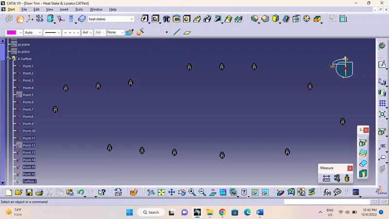
And now we have to make more heat stakes on a point which is given in Class A Surface.
- Firstly we have to copy that locator and paste special… in a Door trim file and select a Paste with link.
- And select a translation commend and choose point to point option.
- Select start and end point
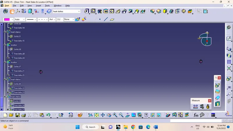
Locator
- Firstly we make a plane on a point which is given in a Class A Surface with reference to tooling axis.
- And make a positioning sketch with reference to plane and point and make a two line.
- And pad it and also make sure the height of heat stakes should be more than to locator.
- After pad it give a Draft, chamfer, and fillet on it.
- And this do a unitrim.
And now we have to make one more Locator on a point which is given in Class A Surface.
- Firstly we have to copy that locator and paste special… in a Door trim file and select a Paste with link.
- And select a translation commend and choose point to point option.
- Select start and end point
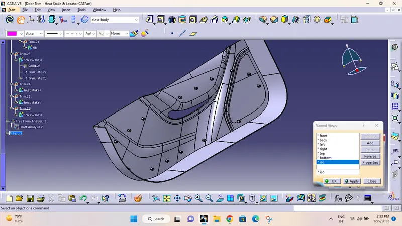
Isometric View
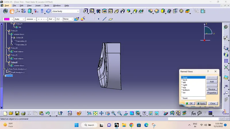
Front View
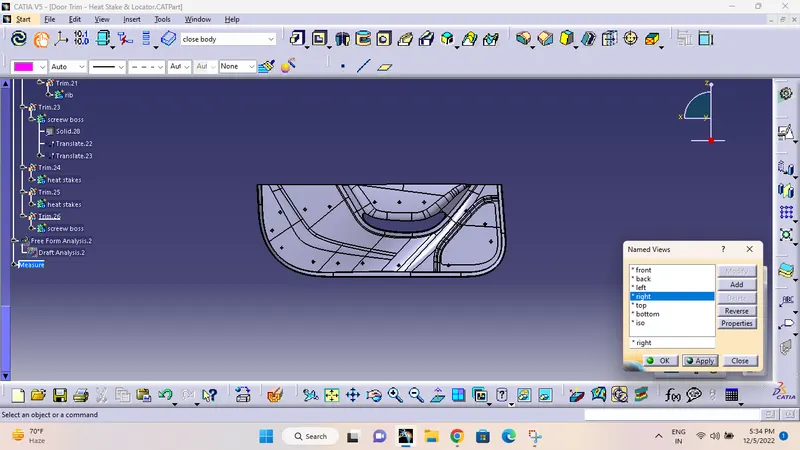
Right Side View
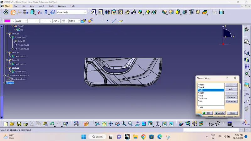
Left Side View
Top View