Week 9 - Project 1 - Door Trim Lower with Engineering Features
Door Applique Design with Engineering Features
Objective :
To create the Door Applique Plastic component through the given Class-A surface. To begin with, the tooling axis for the given Class-A Surface should be created meeting the requirements of the draft angle and at the end perform the Draft analysis on the model.
To create the Heat Stakes and the locators, considering the design rules.
Procedure :
Firstly, we have to create the plastic part from the given CLASS-A surface by creating the CLASS-B and CLASS-C surfaces. Draft analysis is carried out on the plastic part to ensure that the developed surfaces should meet the injection molding standards. Later create the 4 way and 2 way locators as required and heat stakes are designed on the door applique.
DOOR APPLIQUE -
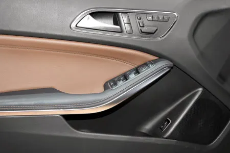
It is the part of the car door panel which is attached to it, which provides aesthetic look to the door panel or to functionally cover aesthetically non-pleasing portions of the vehicle.
LOCATORS -
Locators are the features which are produced on the rear side of the plastic part, which allows proper alignment during assembly with the mating part. They also ensure the precise fit in the initial stages of the assembly. Locators may so many types, mainly four-way or two-way type.
HEAT STAKES -
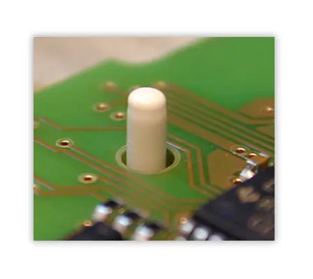
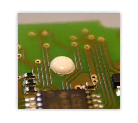
Heat stakes are extruded boss type plastic features which are provided on the plastic component which allow heat staking (plastic welding). Heat staking also known as thermoplastic staking is the process of joining two dissimilar materials together.
Design process :
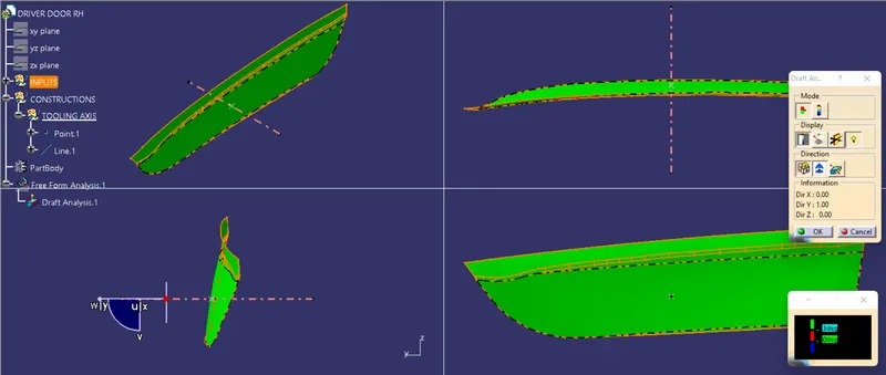
DRAFT ANALYSIS -
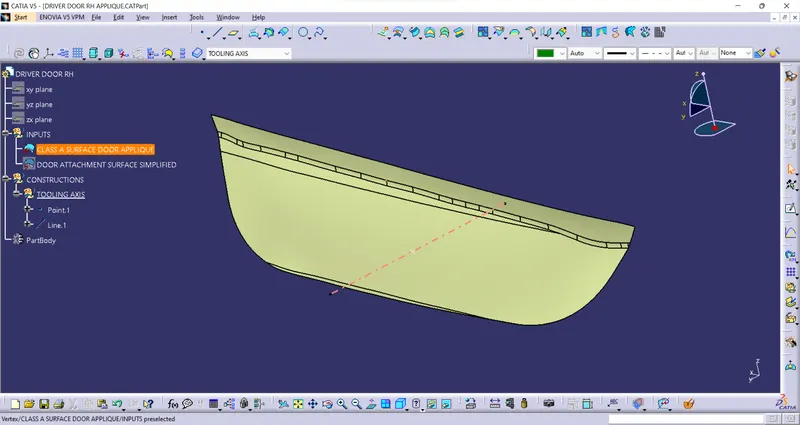
Create the tooling axis by taking reference to the point produced on the surface
DRAFT ANALYSIS -
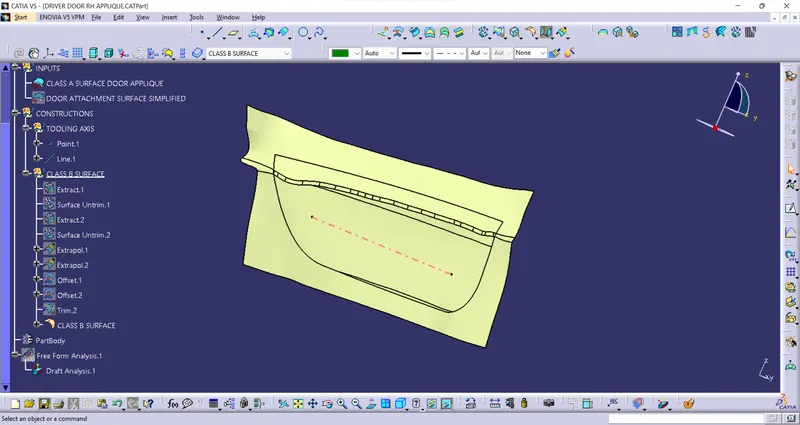
CLASS-B SURFACE -
Extract the surfaces of the door applique and untrim them. Extrapolate the both the surfaces and give an offset of 2.5 mm. Trim the unwanted extensions and apply the fillet
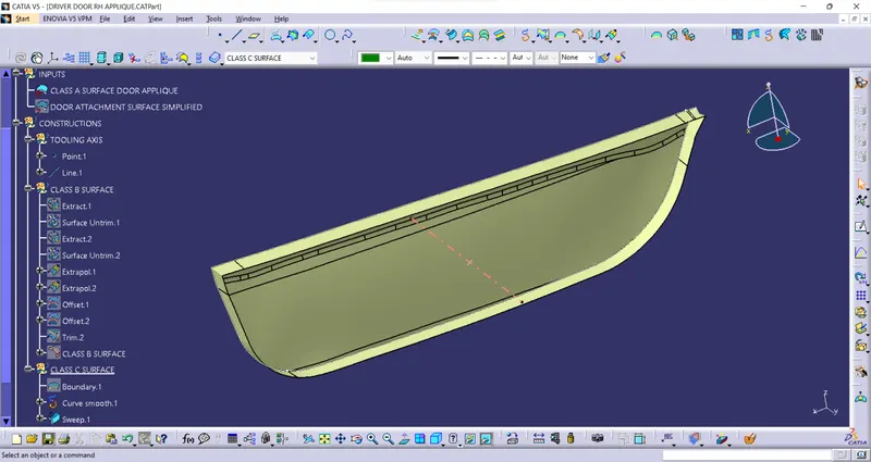
CLASS-C SURFACE -
Create the boundary of CLASS A surface. Smooth the boundary curve and sweep the curve with the draft direction with an draft angle of 3 degrees with respect to the tooling axis.
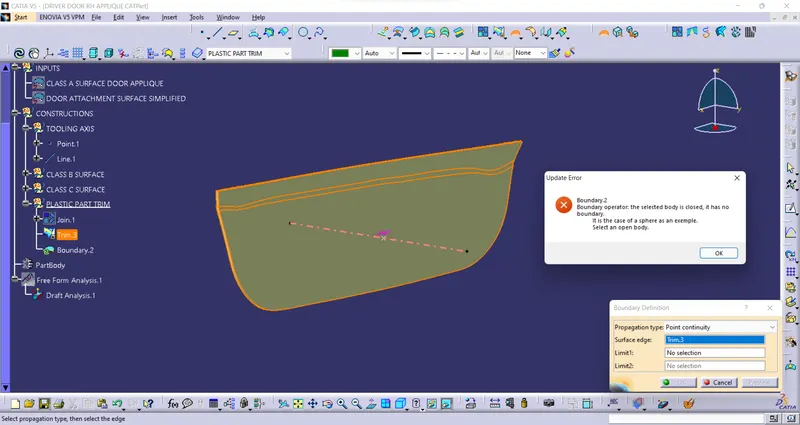
PLASTIC PART -
Join both the CLASS A surface and the CLASS C surface. Now trim this joined surface with the CLASS B surface. Check for the open gaps. Close the surface with the solid material
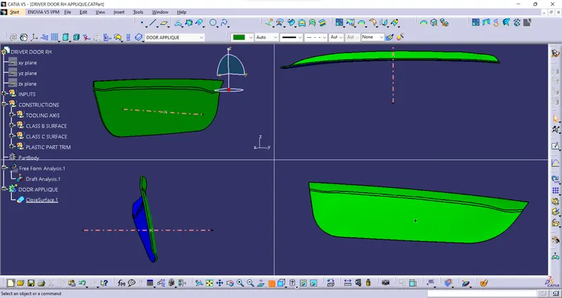
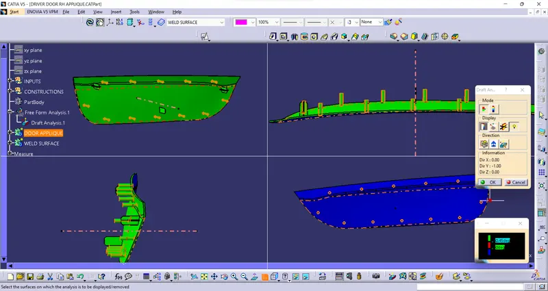
DRAFT ANALYSIS -
LOCATOR PINS -
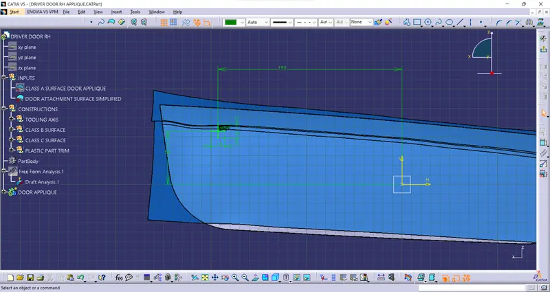
Create a point on the surface to which the applique is welded and make a plane there. Draw a positioned sketch on that plane as shown
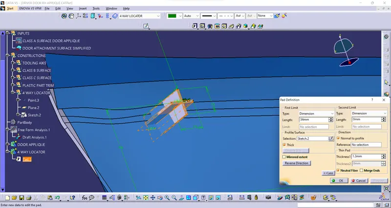
Create the thickened pad
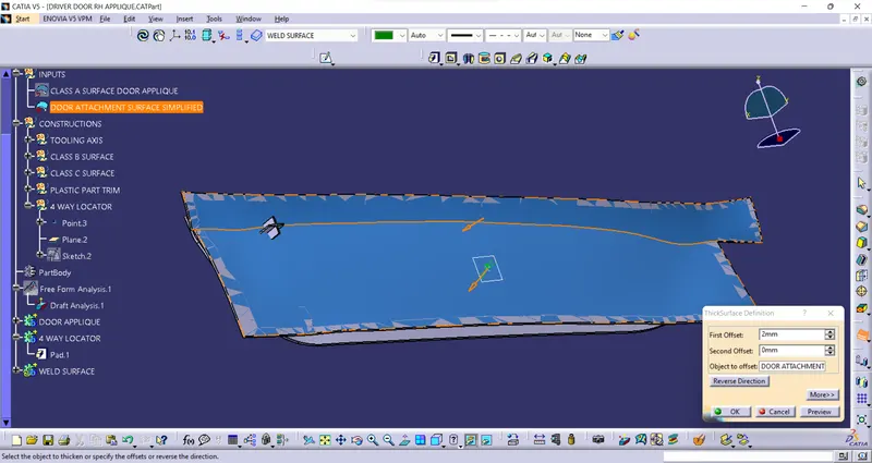
Thicken the reference surface
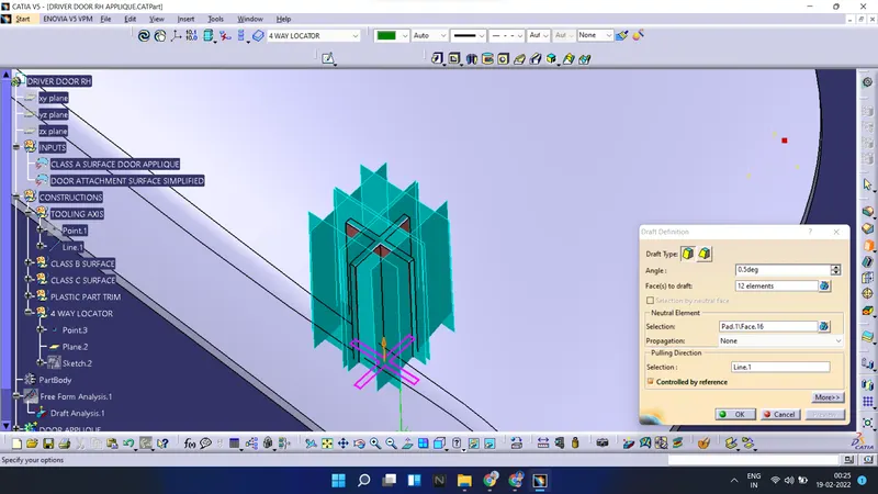
Apply the draft
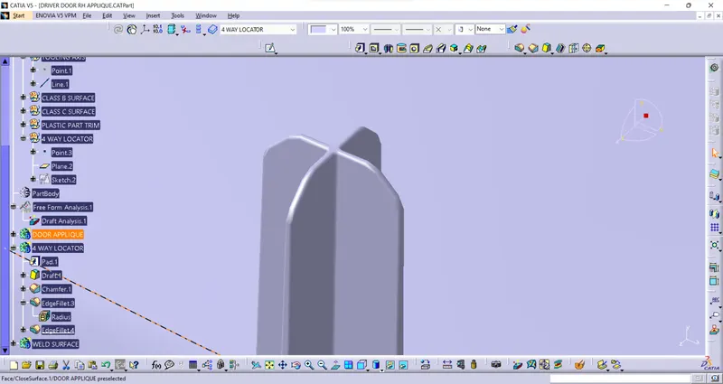
Chamfer the edges and apply fillets
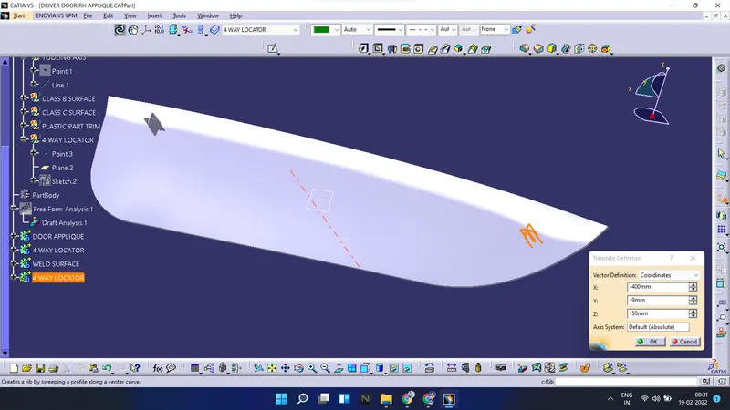
Copy the 4 way locator and translate it to the new place
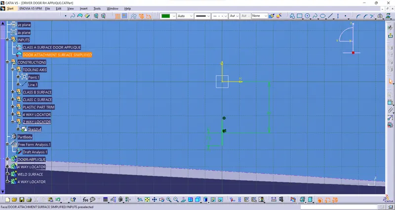
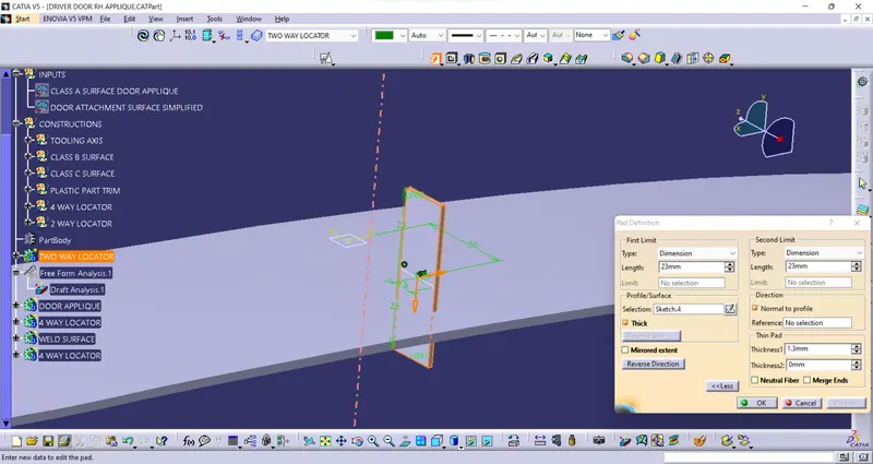
Draw the positioned sketch for two way locator
Pad the profile
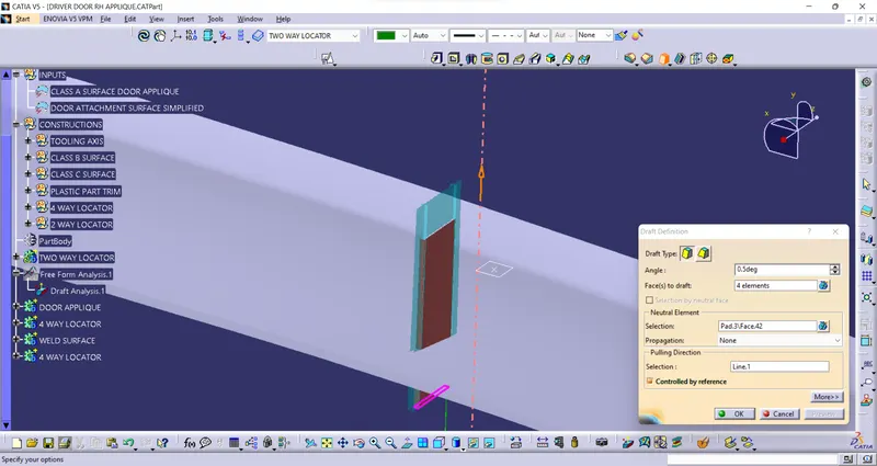
Apply draft
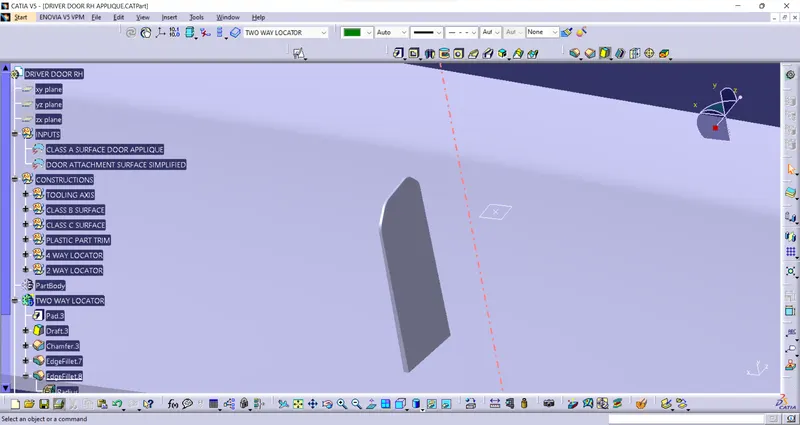
Apply chamfer and fillets
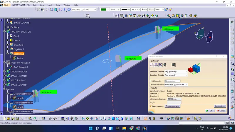
Make sure that heights of all locator pins are almost equal when they are measured from the surface to be welded. Union trim them with the door applique
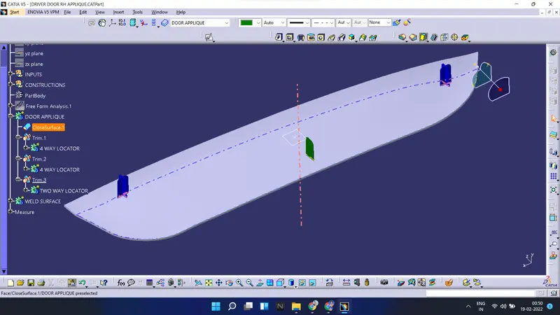
HEAT STAKES -
Extract the boundary of the CLASS A surface and create the parallel curve
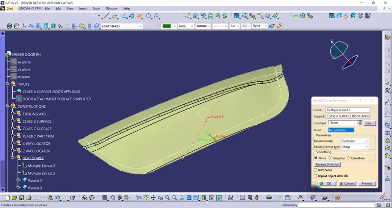
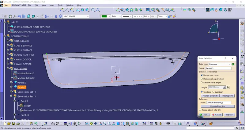
Create the equidistant points on the curve
Create the sketch for the heat stake
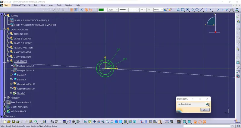
Pad the sketch
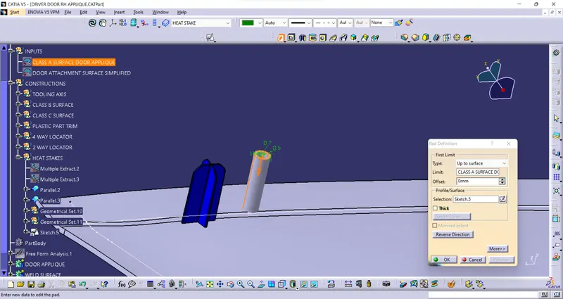
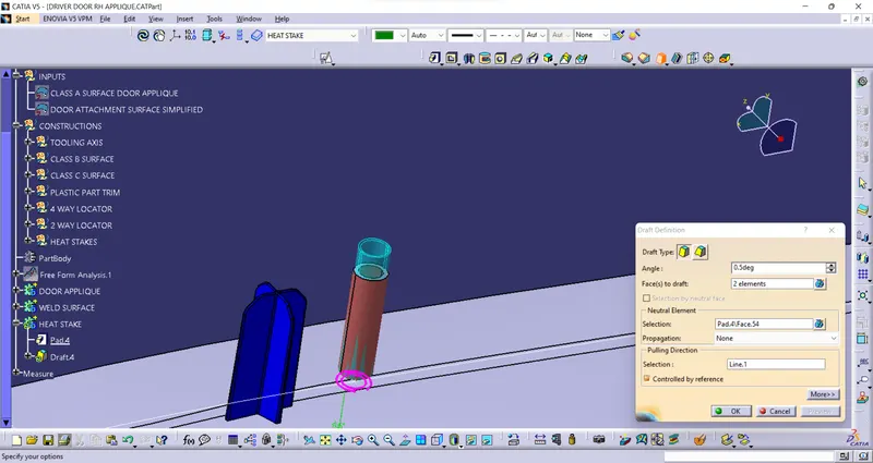
Apply draft to the heat stake
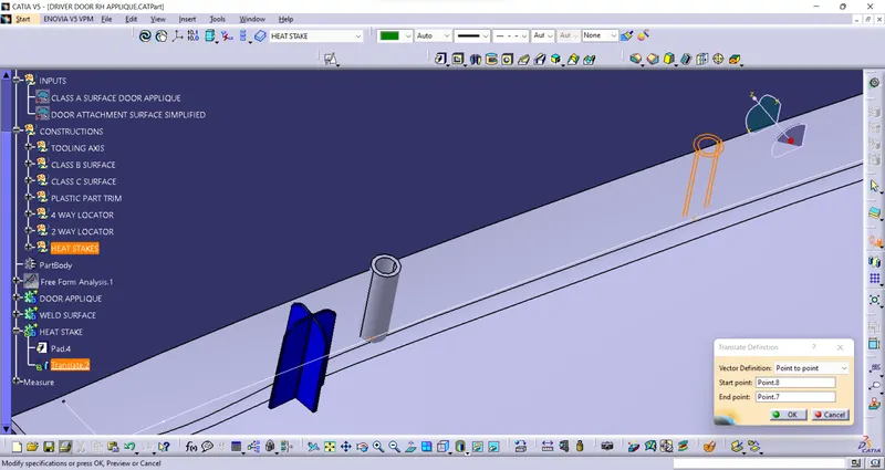
Translate the heat stake from point to point and do the same for all
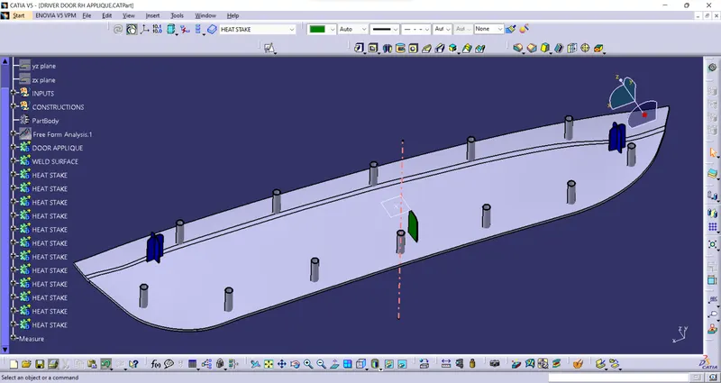
union trim the heat stakes with the door applique
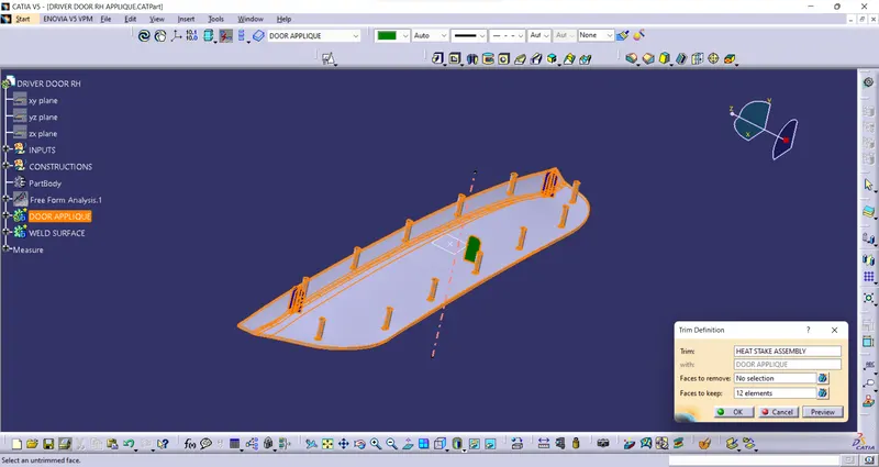
CLEARANCE HOLES -
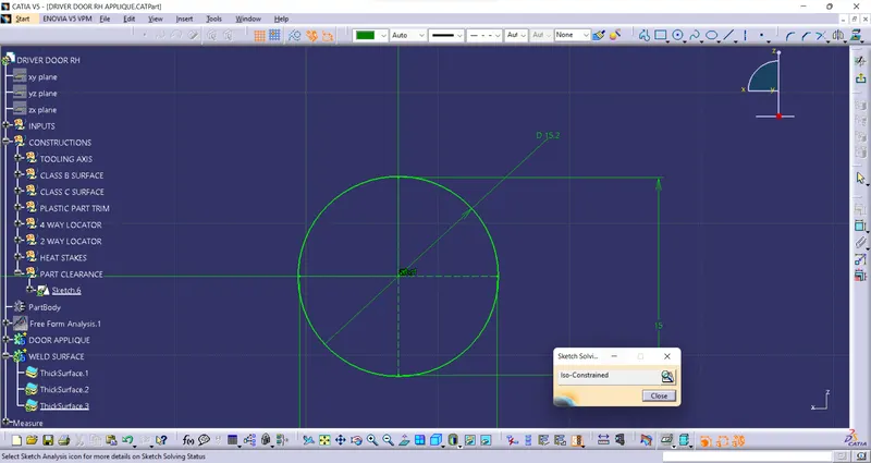
We have to give 0.1 mm clearance on each side of the locator and 0.5 mm clearance for the heat stake
Draw the sketch for clearance hole
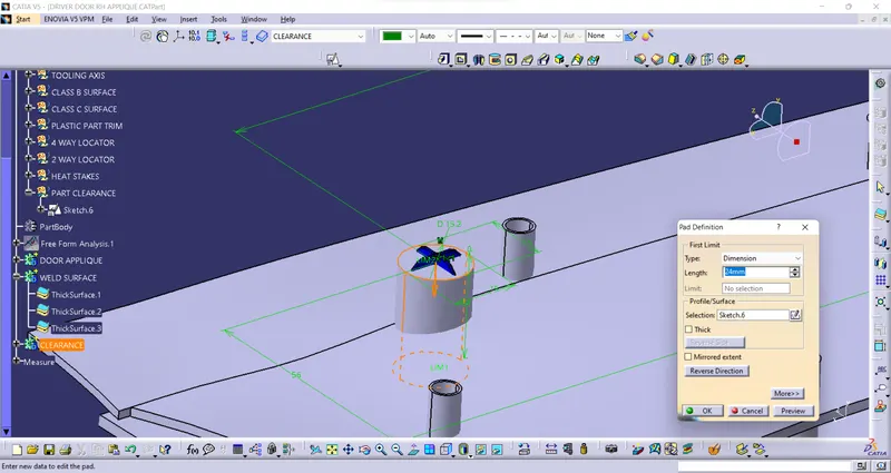
Pad the sketch
Apply draft
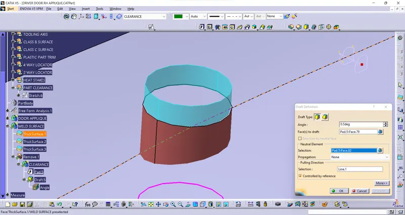
Do same for all locators
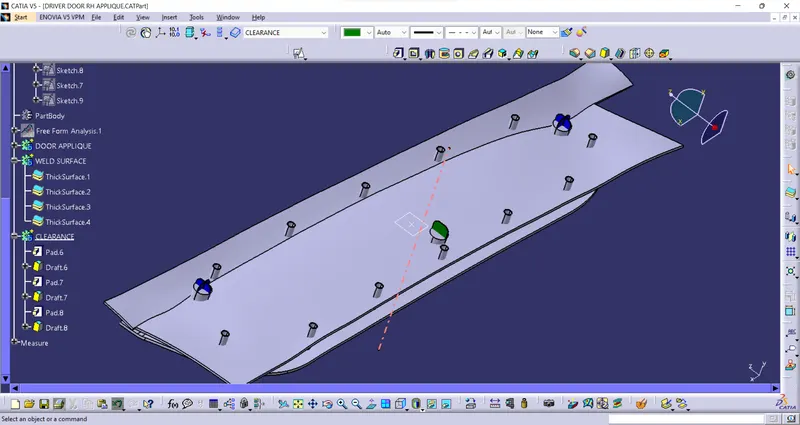
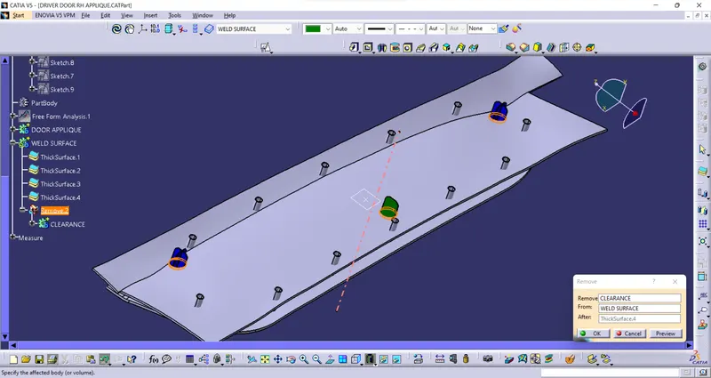
Remove them from the weld surface
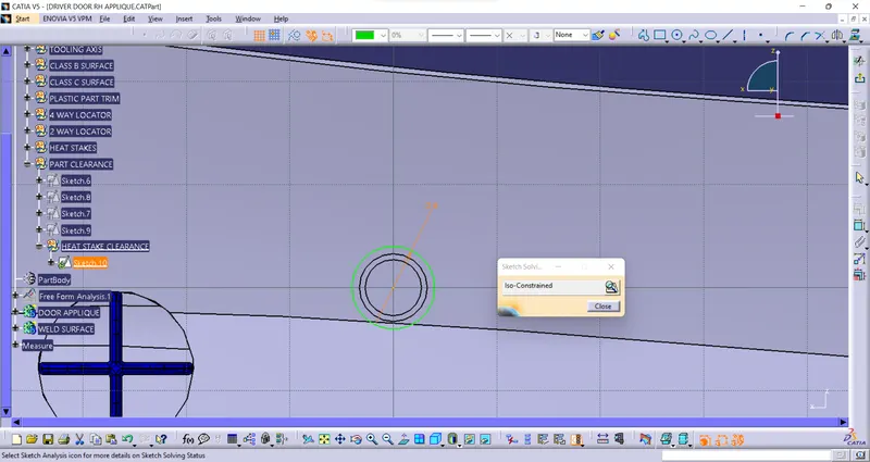
Similarly, draw the sketch for the heat stake clearance
pad the sketch
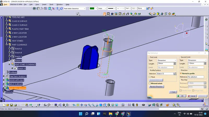
apply draft, copy and translate them all
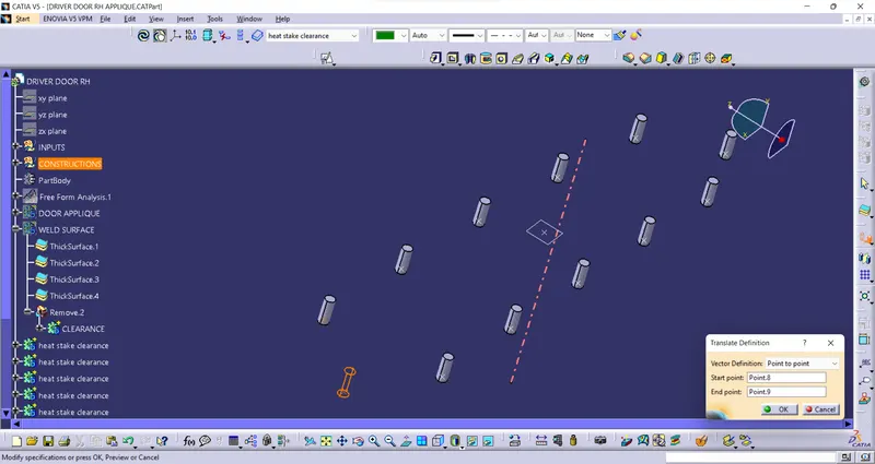
Remove them with the weld surface
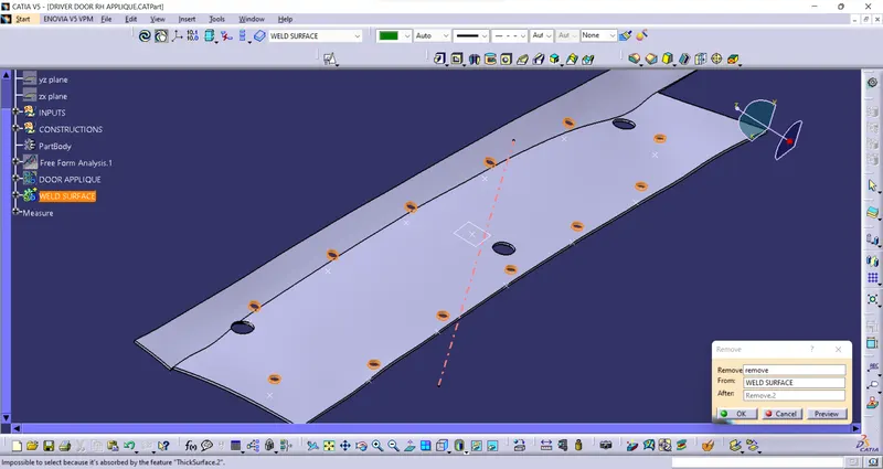
Final view
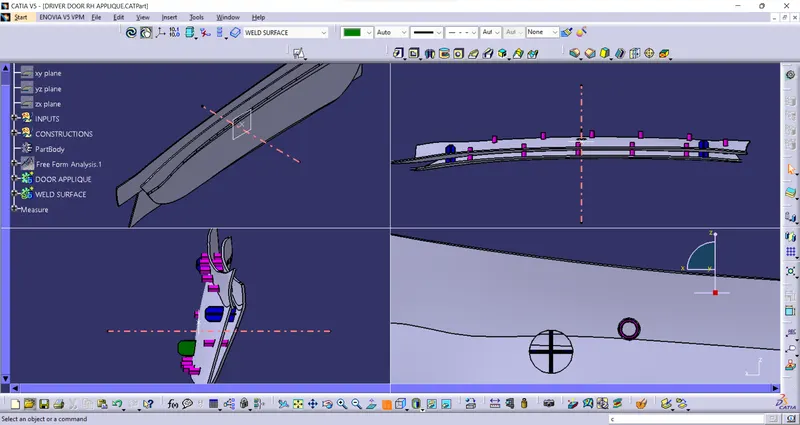
DRAFT ANALYSIS -
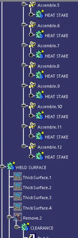
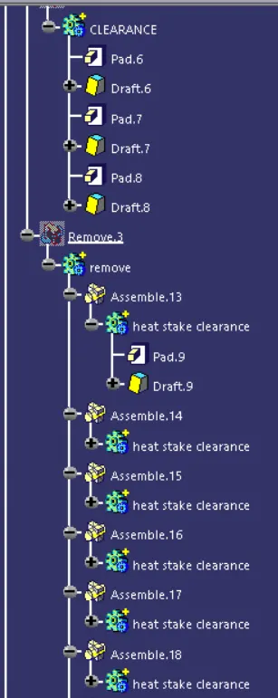
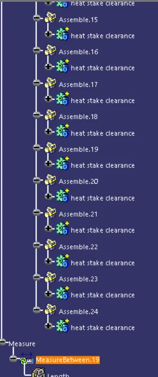
Tree structure :
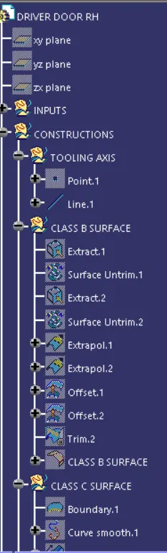
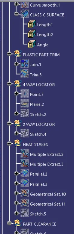
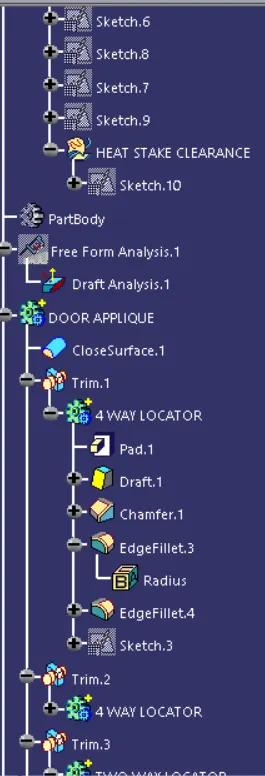
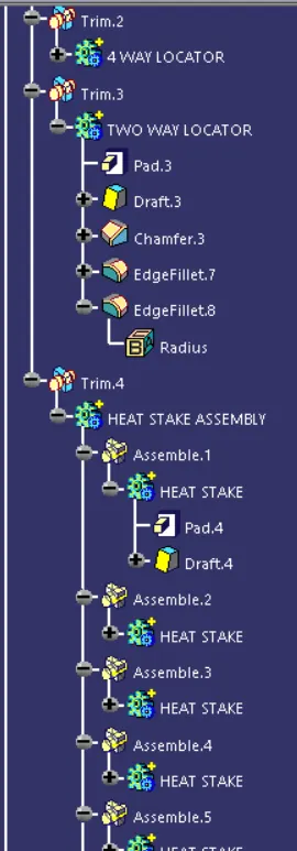
Conclusion :
From the given CLASS A surface of the door applique, the plastic model is developed by creating the CLASS B and CLASS C surfaces.
Locators and heat stakes are added to the plastic part. Draft analysis is carried out on the final part, which states that the part designed will meet the injection molding requirements.