Week 9 - Project 1 - Door Trim Lower with Engineering Features
DOOR TRIM LOWER
Aim:
To Create the Door Trim Lower Plastic component through the given Class-A surface. To begin with, the tooling axis for the given Class-A Surface should be created meeting the requirements of the draft angle and at the end perform the Draft analysis on the model.
Introduction :
The input of the product designer is in the form of the A-class surface. The job of the product designer is to create the B and C surfaces keeping all the aspects for the mold.
Class A surface:
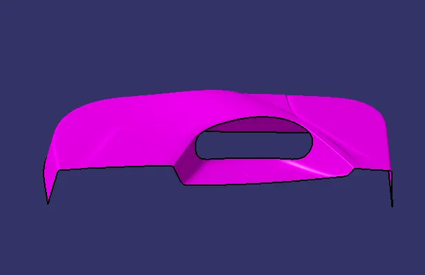
- Class A surface is a Styling surface or aesthetic surface get it from the styling team. we will design the plastic component by using the Class A surface as input.
- Check all the views of the given class A surface that can help us to understand and get more understanding of the component.
- Connectivity of the class A surface that there is no gap between the component, by using joining command or boundary command we can check.
TOOLING AXIS:
- Tooling axis can be classified into two methods
- direct method
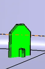
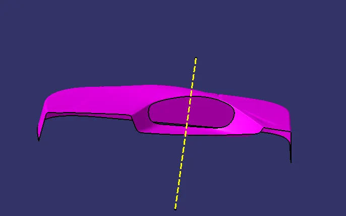
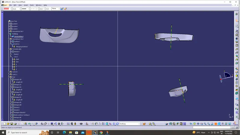
- For this model, to use a line at mid-point of the base of the coin holder
- Due to perpendicular walls of the class A surface
DRAFT ANALYSIS:
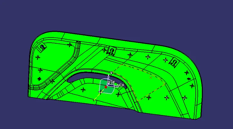
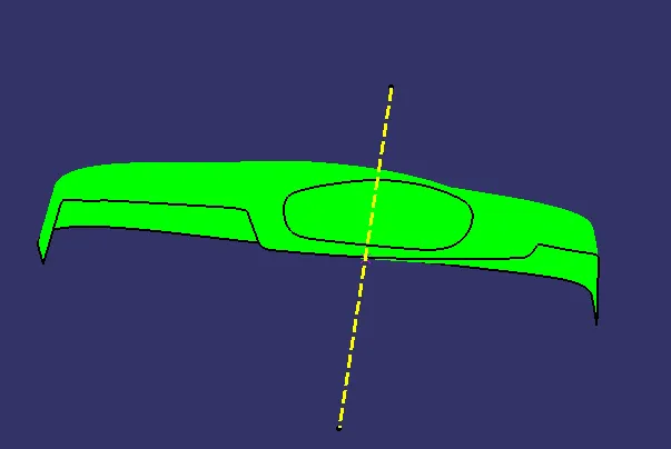
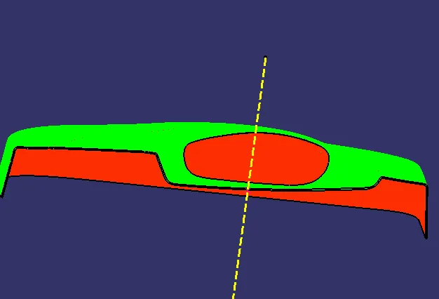
- The Drafting analysis was performed on the class-A surface by using the Feature Draft Analysis command.
- Using this command, the compass was set on the main tooling axis and the Draft angle was changed to 3 degrees.
CREATING THE CLASS B SURFACE
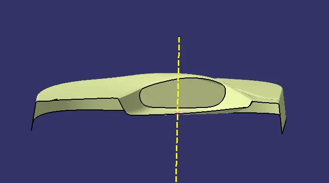
- Class B surface is to be creating the engineering features and offsetting the surface of class A. Firstly we will extract surfaces by using the extract command and from the class A surface. And if there are any patches we have to make it a smooth surface and finally get the complete boundary.
CREATING THE CLASS C SURFACE
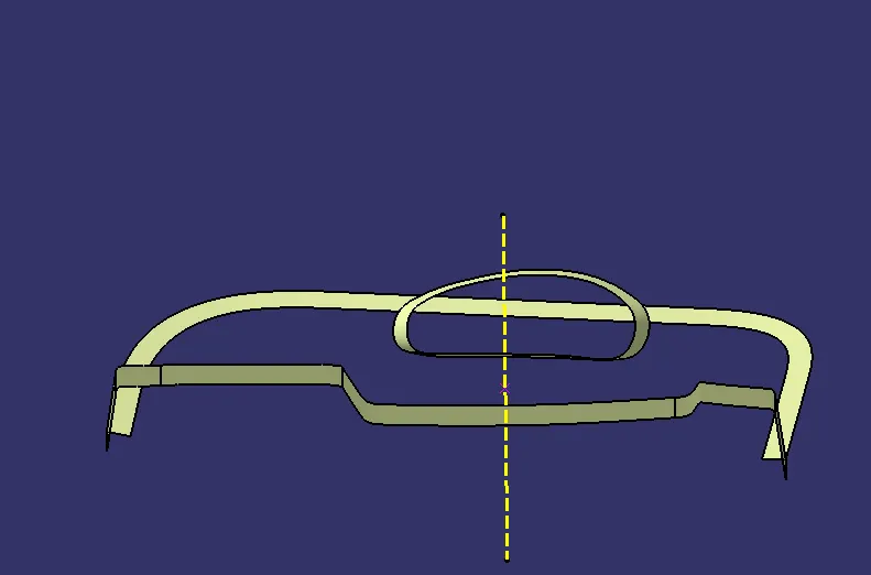
- Class C surface is connected the Class A and Class B, For the class C surface, we need to create the entire boundary of the component by using the boundary command.
- And also creating the best way for the tooling direction to manufacturing easily in an effective way.
- By using the sweep command we can combine them and trim the surfaces so we can get the completed closed surface body and draft angle given as min 3 degrees.
- Before trimming the most important things join them all.
- After the body has to be closed by using the closed surface in part modeling.
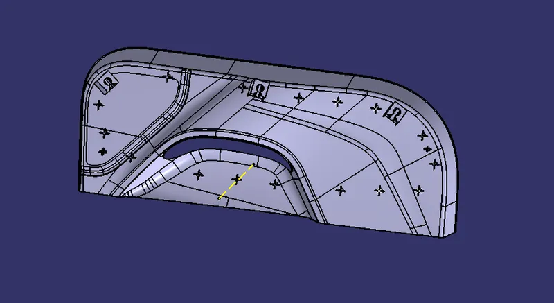
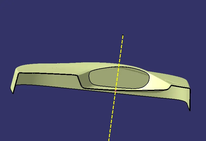
final body
Draft Analysis for the Final Plastic body:
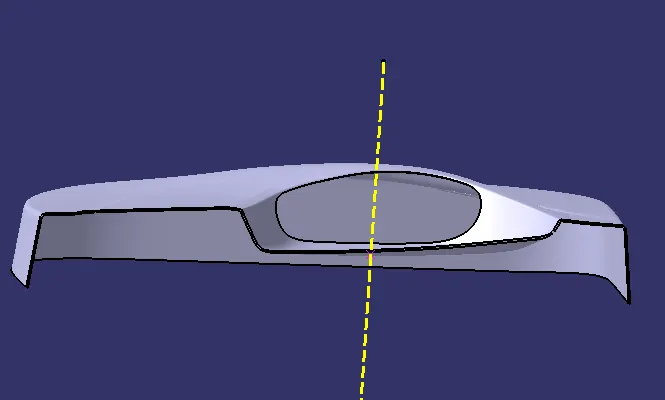
FINAL SOLID BODY
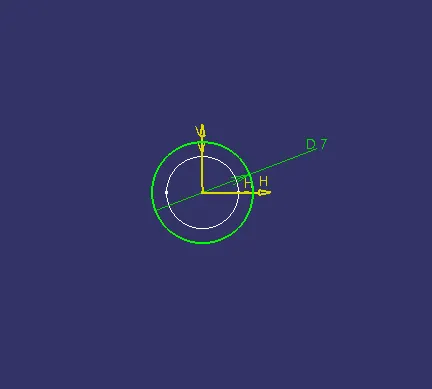
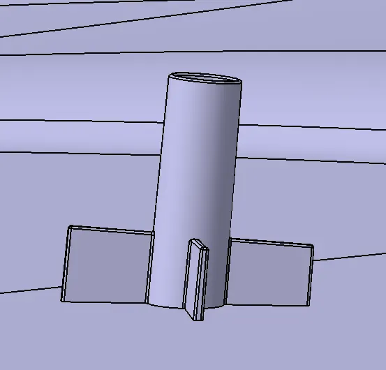
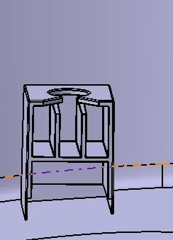
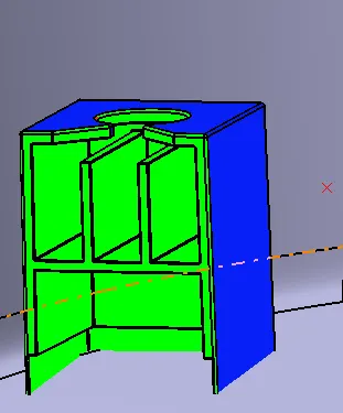
2-WAY LOCATORS:
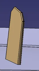
A 2-way locating pin restricts motion along 1 axis (or 2 degrees of Freedom), like a round pin in a slot. Likewise, a 4-way pin restricts 4 degrees of freedom along 2 axes. A round locating pin located concentrically in a hole is a common application of a 4-way pin, and helps to further secure the piece.
4-WAY LOCATORS:
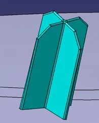
4-way mean you prevent movement at 2 axes (+X, -X, +Y and -Y) on the plane. Generally, you have cylindrical pin on the fixture and circular hole at workpiece part.
DRAF ANALYSIS