Week 9 - Project 1 - Door Trim Lower with Engineering Features
TOOLING AXIS CREATION
Tooling axis defines the movement of tooling (core & cavity).
First seek for the best possible direction for tooling axis.
Generally tooling axis is either in X, Y or Z direction whichever is best for tooling clearing.
In this case,
FOR MAIN TOOLING AXIS -
A surface from the class A model is selected for creating a point for tooling axis.
Create a point at center of the surface.
Introduce an axis system on the point.
Y-component is taken as the best possible direction for tooling axis through the created point.
Bisecting method is used for creating a line as tooling axis between two possible directions through a point.
Bisecting method can be optional in this case.
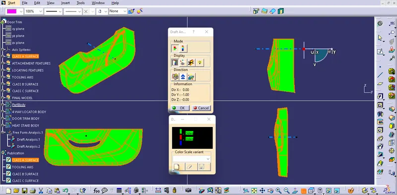
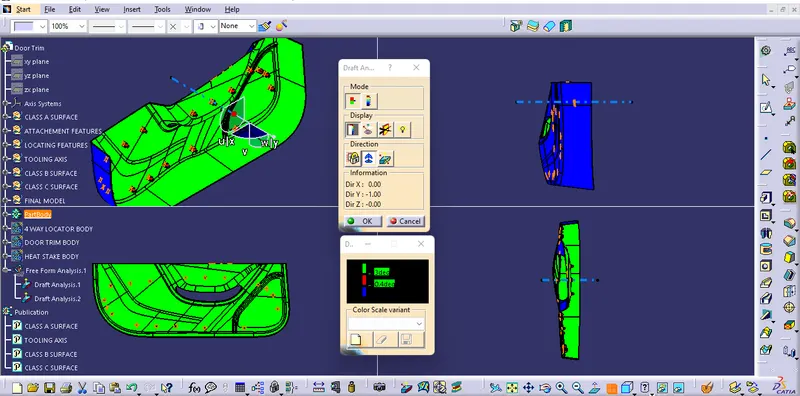
DRAFT ANALYSIS
Change the view mode to Customize View Parameters and select the Material option from the Mesh.
FOR CLASS A MODEL -
Introduce the compass, drag and align it with the line (MAIN TOOLING AXIS).
Lock the direction of the draft.
Draft angle compared within 0⁰ to 3⁰.
FOR FINAL MODEL -
Introduce the compass, drag and align it with the line (MAIN TOOLING AXIS).
Lock the direction of the draft.
Draft angle compared within 0.4⁰ to 3⁰.
========================
TOOLING AXIS
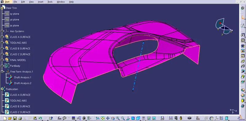
DRAFT ANALYSIS
CLASS A SURFACE
FINAL COMPONENT
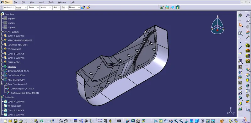
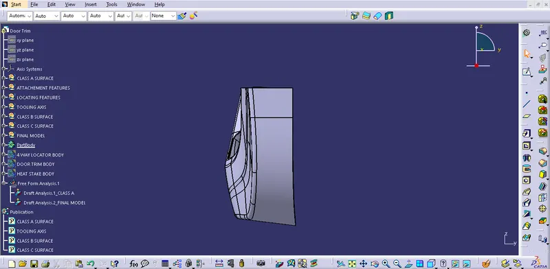
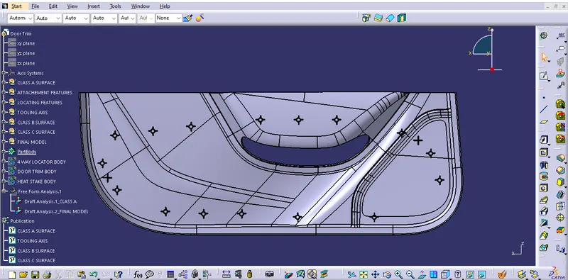
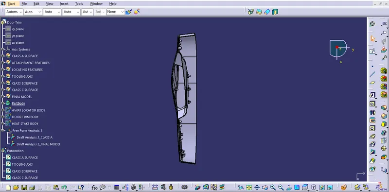
ORIENTATIONS
==============================