Week 9 - Project 1 - Door Trim Lower with Engineering Features
The draft angleis given to body inorder to avoid the scratches on the surface due to friction, also it allows for the part to release from the mold easily.
The minimum draft angle is given 0.5 degree and upto 3 degree is accepted.it is given with respect to tooing axis.
Drafting is done on C surface which connects A and B surface.
The Draft Analysis allows the user to easily analyze a part for proper draft angle. A Draft Angle describes the amount of taper for molded or cast parts perpendicular to the parting line.
during drawing, Initially we have given the A surface. First step is to draw the tooling axis by finding the most appropriate direction and using the bisection of tooling axes along X and Y
In door trim we selected an surface and extracted it, then created a point on it with zero cordinates and insert an axis . then we draw a line along y axis and named it as tooling axis since we do not have a particular inclination in both xy and yz planedirection by intersecting method,if needed. By inersecting the a suface and a plane , we get the line along it. we can give the drat angle on a body if there is large flat surface or on a circular hole if any.
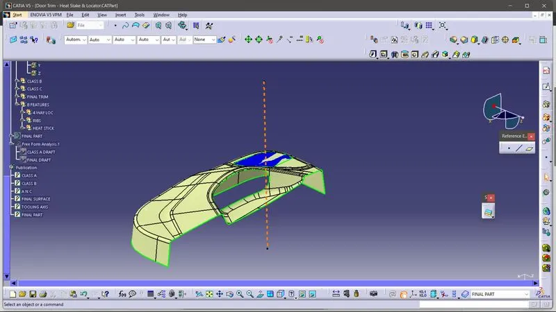
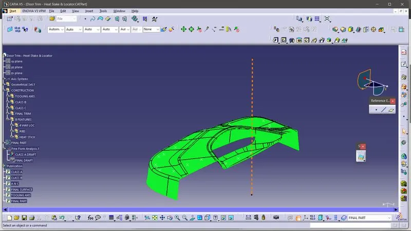
During the draft of A surface we give the draft angle 2.9 degree limit along the tooling axis.
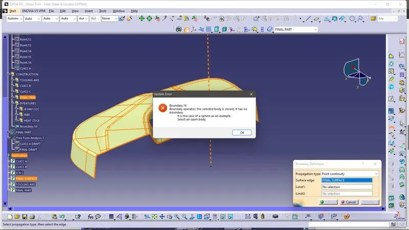
after creating the C and B surface we trim and join together to get the total surface and check weather its closed.
Then we fill the surface by close body
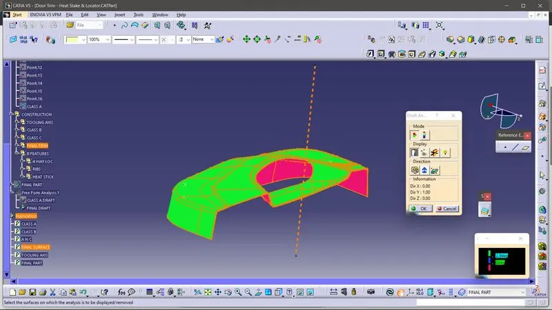
at the final surface draft also we gave the angle 2.9 degree
Then we add b sid efeatyres like heat stake,4 way locator and ribs.
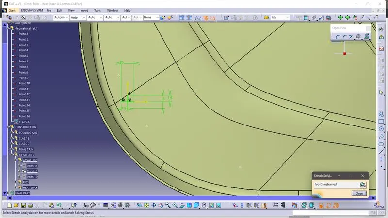
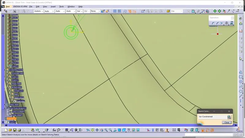
and pad it and give the draft of minimum0.5 degree.
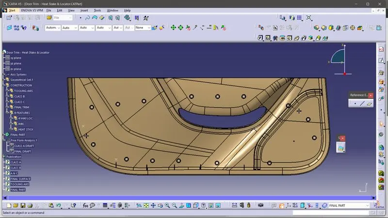
we took the reference point from the question.
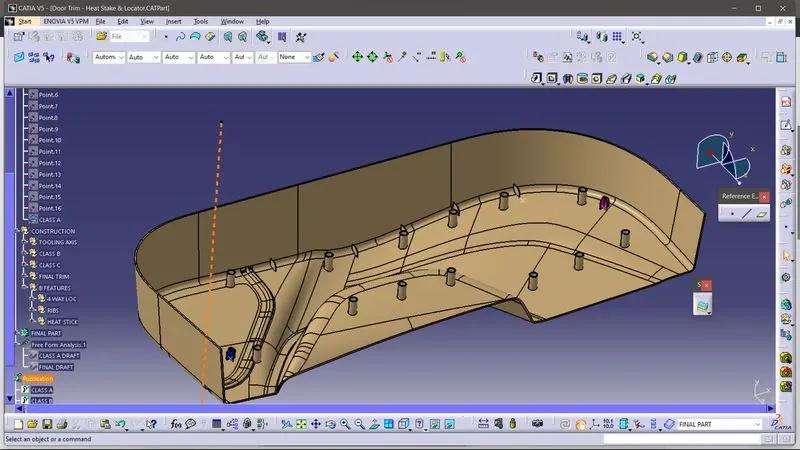
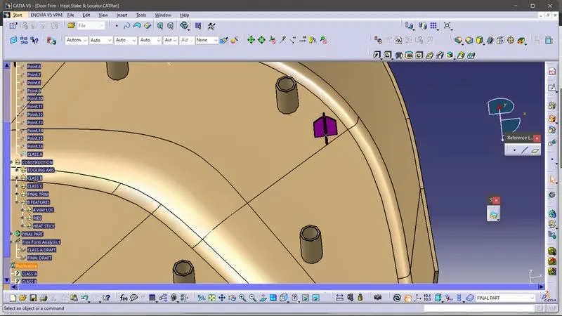
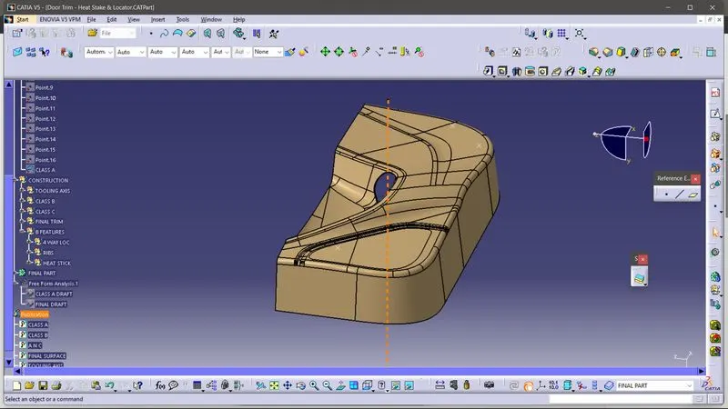
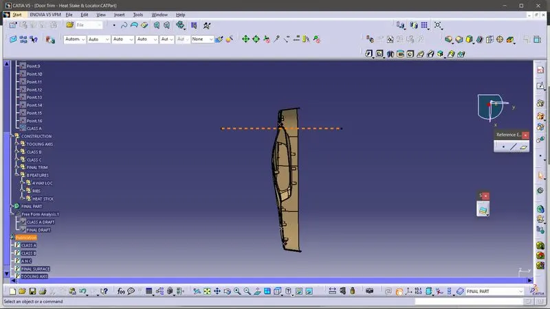
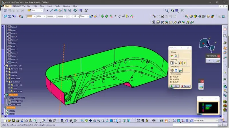
since the minimum angle of draft for b side features is 0.5 degree we gave 0.45 degree at the draft analysis time.