Week 9 - Parametric study on Gate valve.
Aim: To perform a parametric study on the gate valve simulationby setting the opening from 10% to 80%.
Objective:
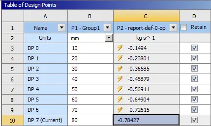
- Obtain the mass flow rates at the outlet for each design point.
- Calculate the flow coefficient and flow factor for each opening and plot the graph.
- Discuss the results of the mass flow rate and flow coefficient.
Description:
A gate valve consist of a sliding plate that controls the flow of fluid in pipe/channel. Components of Gate Valve includes Gate Disc,Bonnet, Spindle, Hand wheel and body(casing). They are operated using handwheel which turns a screw to lift or lower the gate. It consist of a sliding disk that moves vertically, perpendicular to the path of the fluid flow. It can be used for a wide range of liquids and provides a tight seal when closed. Selection of a gate valve involves, the material used to construct the valve is an important decision to prevent premature value failure. To select a proper valve material the following parameters needs to be considered service temperatures, operating pressures, effectiveness of coating on materials, material availibility and its cost and compatibility of materials with the injecting fuel/liquid.
PROCEDURE:
GEOMETRY:
Import the geometry into space claim
Gate Disc to rise 10 mm hide the bottom. Select the move command and gate disc is moved to 10 mm.
Extract fluid volume from Prepareà select edges inlet and outlet (hiding the bonnet) --> click complete
Pull --> extend the fluid region select inlet and outlet
Suppress the solid geometry untick all only fluid volume should exist
MESH:
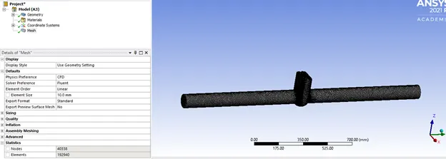
Fluid Volume is imported onto the meshing module
Default Automesh is applied
Named Selection--> Inlet and outlet
Close and Update the mesh module

SETUP:
Double precision with single processor
Inlet is denoted by blue and outlet face is denoted by red
Gravity z = -9.81
Material --> fluent --> water
Cell zone condition --> water and delete the material air
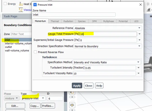
Boundary Condition
INLET: Pressure Inlet --> 10 Pa (gauge total pressure)
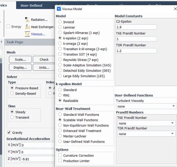
Viscous Model --> k-epsilon for pipSince the flow is turbulent K epsilon is selected --> Realizable k epsilon --> Scalable wall function
Define the Output: Mass Flow rate at the outlet
Definition -> new -> flux-> Mass reportà select outlet--> tick report file
Post processing
Insert plane --> cut through the fluid volume-->create contour--> velocity contour in that plane
ANIMATION
Solving --> create --> solution animation--> contourà change animation view and use it as active
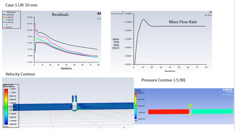
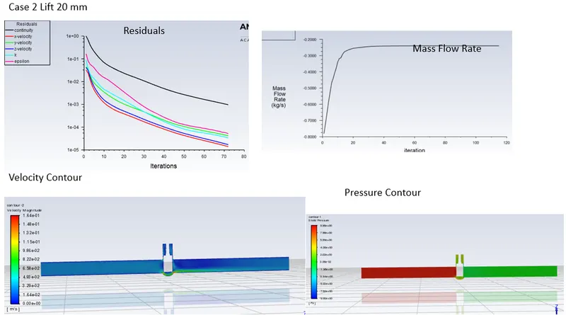
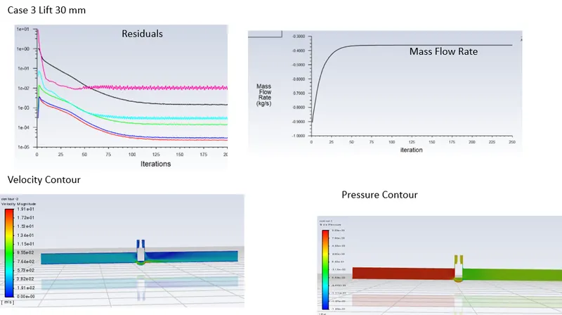
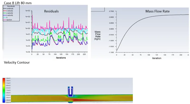
Mass flow rate is negative since in fluent the fluid flowing outward will have a negative sign convention
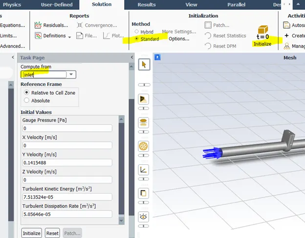
Parameterization
Select the Move command having only the gate disc. Use the component select option and select the gate disc --> drag it set it by 10 --> select the parameter option
Fluid volume adaption in the gate disc movement --> use the update volume body as context
RESULTS AND DISCUSSION
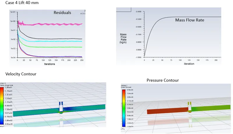
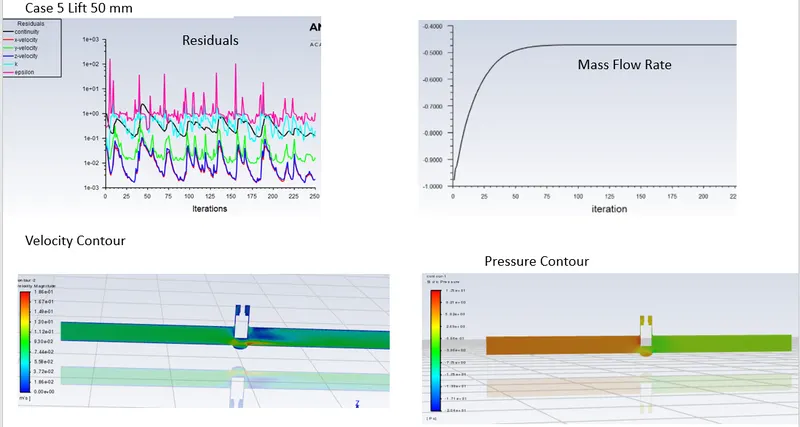
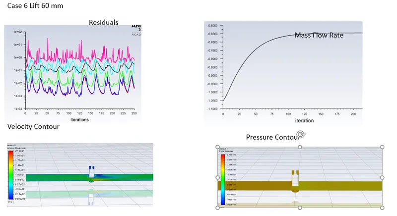
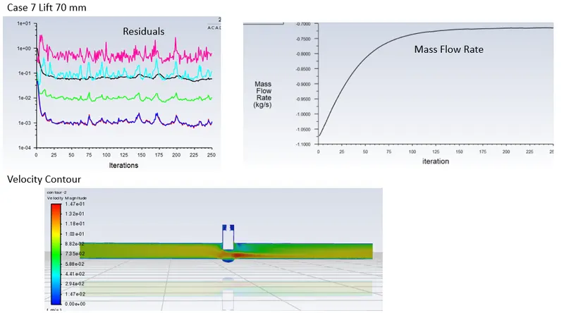
| Lift or Valve Opening(%) | Mass Flow Rate Q (kg s^-1) |
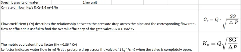
ΔP - pressure drop across the valve (Pa) | Flow factor - Kv | Flow coefficient - Cv |
| 10 | 0.1494 | 10 | 53.784 | 62.174304 |
| 20 | 0.23801 | 10 | 85.6836 | 99.0502416 |
| 30 | 0.36585 | 10 | 131.706 | 152.252136 |
| 40 | 0.46879 | 10 | 168.7644 | 195.0916464 |
| 50 | 0.56911 | 10 | 204.8796 | 236.8408176 |
| 60 | 0.64904 | 10 | 233.6544 | 270.1044864 |
| 70 | 0.72615 | 10 | 261.414 | 302.194584 |
| 80 | 0.78427 | 10 | 282.3372 | 326.3818032 |
Plots
Valve opening Vs Mass flow rate:
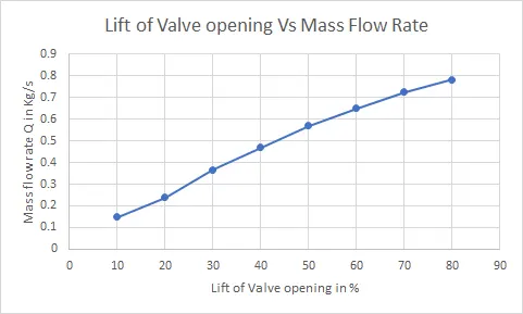
Inference: Mass flow rate increases with increase in lift of valve opening
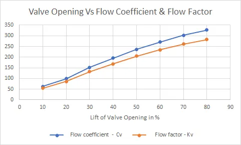
Valve opening Vs Flow Coefficient
Inferences
It is envisaged from the above results that
- As the opening of the gate disc increases-the mass flow rate of fluid also increases.
- At the maximum lift of the gate disk fluid flows freely without any disturbance or restriction.
- flow coefficient and the flow factor increases with increase in valve openings i.e. as lift increases the flow factor and the flow coefficient raises.
- velocity contour helps in understanding the behaviour of fluid flow behave w.r.t opening of gate valve. It also indicates the maximum velocity throughout the flow.
- As Lift increases output pressure increases
Conclusion:
The parametric study was performed on the gate valve by varying the lift from 10% to 80%. The following inferences were made during the study:
As lift of gate disc increases--> fluid flow increases and flow coefficient & Flow factor increases proportionally
Thus the study of the effect of opening the gate valve on the fluid characteristics was simualted successfully.