Week 9 Machining with Planer Challenge
AIM: - PERFORM AN EXPLICIT DYNAMIC SIMULATION OF A PLANAR MACHINING OPERATION.
Objectives:
Perform the simulation to find out Equivalent Stress, Total Deformation, and the Temperature of the body for two different tool speeds:
a) 15000 mm/sec
b) 20000 mm/sec
To begin with, the analysis, select the Explicit Dynamics Analysis from the Analysis Systems of the Ansys Workbench and follow the following steps:
1. Open Engineering Data, go to Engineering Data Sources, and add Steel 1006, from the Explicit Materials library, in the project environment.
2. Import the geometry into the project, the geometry in SpaceClaim will look like this:
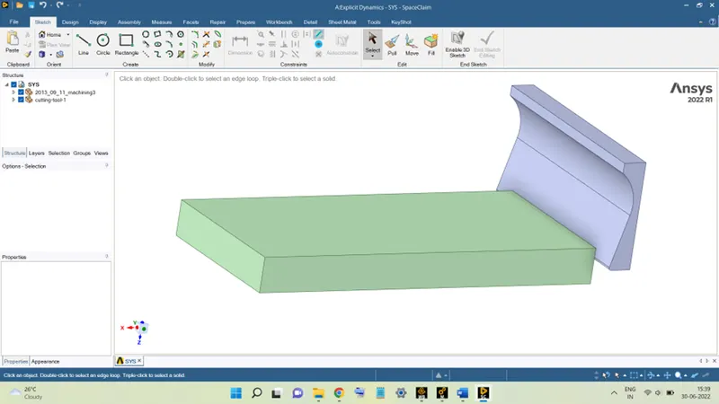
3. In Mechanical Module, rename the parts and assign appropriate materials to the parts, as shown below:
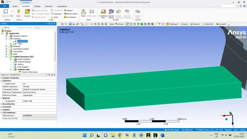
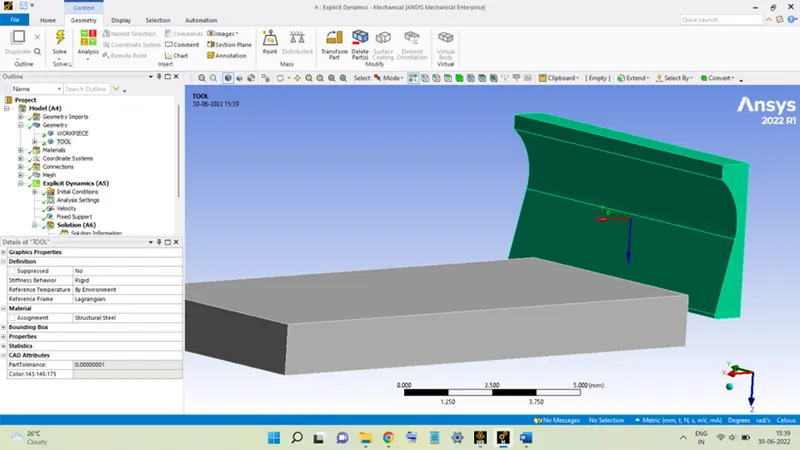
Also, the TOOL is made Rigid for this analysis.
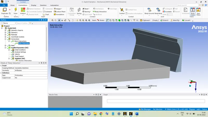
The pre-defined Contacts for the geometry are deleted and the Body Interactions are kept Frictionless.
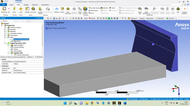
4. The TOOL is meshed using a Tetrahedron mesh method.
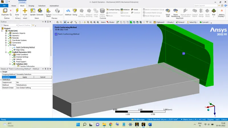
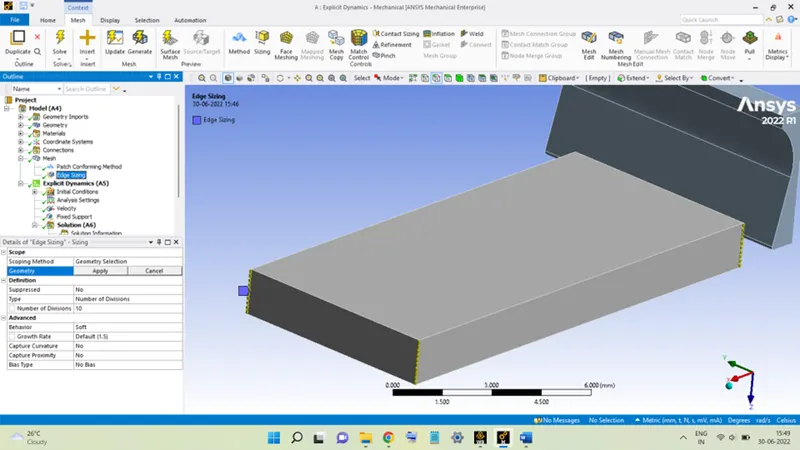
The WORKPIECE is meshed using Edge Sizing, the number of divisions, for each of the 4 edges, was taken as 10.
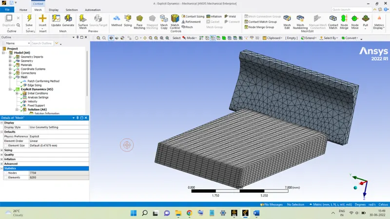
The meshed model will look like this:
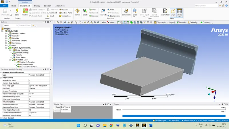
5. In Analysis Settings, the End Time was taken to be 7.5 x 10⁻⁴ sec.
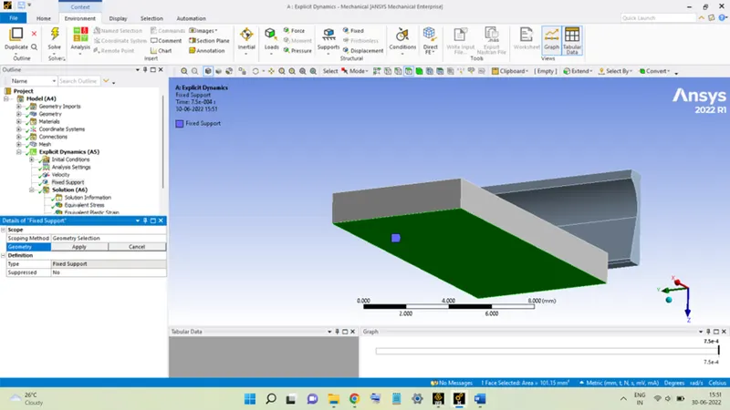
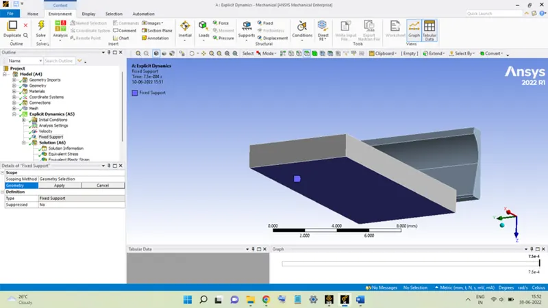
The bottom surface of WORKPIECE was made Fixed.
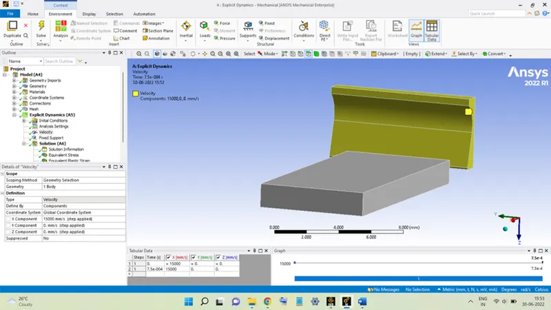
The TOOL is given a velocity along X-Axis equal to 15000 mm/sec for the first case and for the second case it was taken as 20000 mm/sec.
With this, the setup of the analysis completes, hit Solve to execute the analysis.
RESULTS:
CASE 1: Velocity is 15000 mm/sec.
Stress:
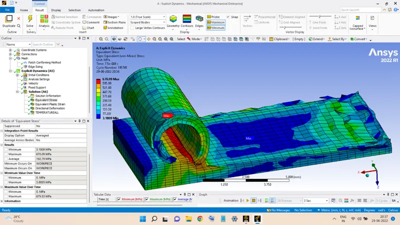
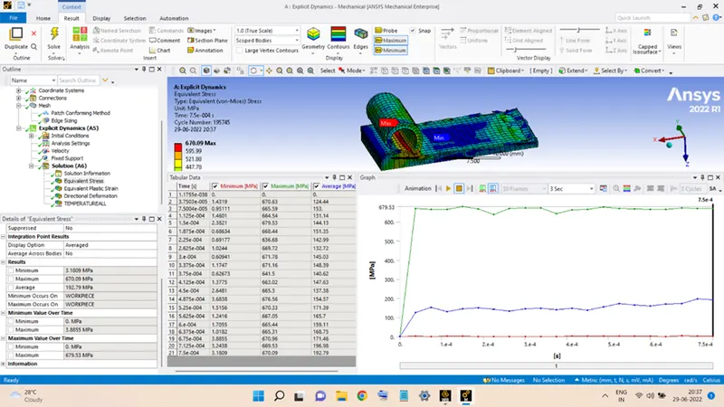
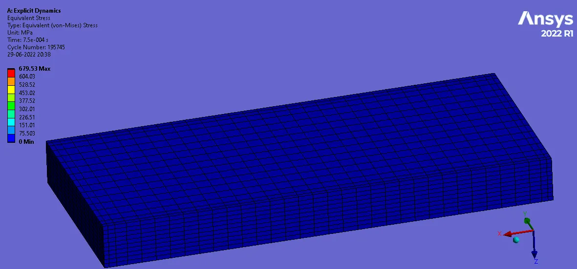
The variation of the stress during the operation is shown in the above figures. The maximum stress value reached is equal to 679.53 MPa. The TOOL was not able to traverse the complete length in the given End Time. The stress variation, from the table, is seen to be almost uniform during the operation.
Deformation along X-Axis:
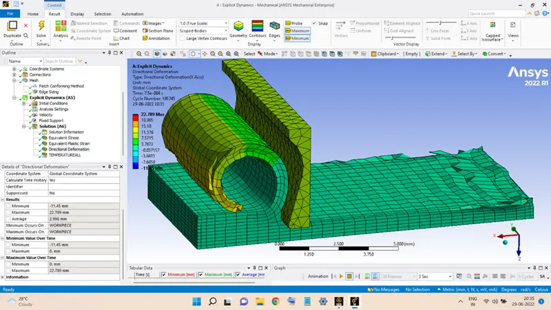
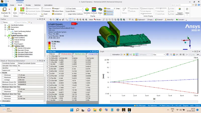
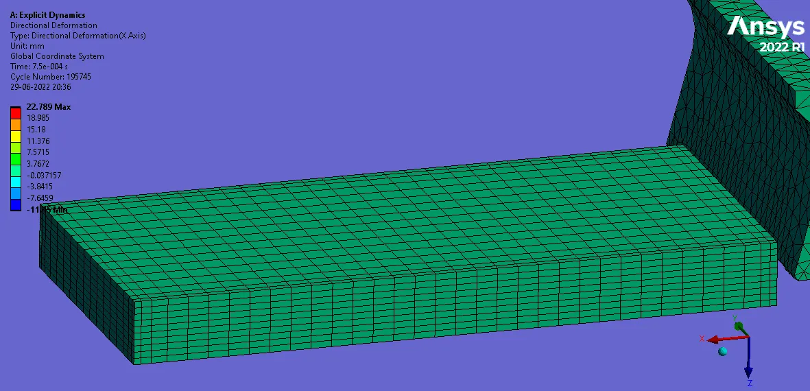
Variation of the deformation experienced by WORKPIECE during the operation is shown in the figures above, the maximum deformation is equal to 22.789 mm.
Temperature:
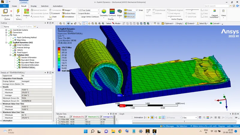
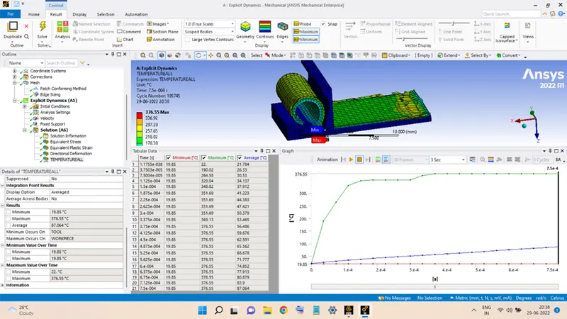
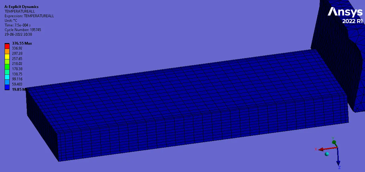
The temperature of WORKPIECE during the operation can be seen from the above figures, its maximum value is equal to 376.55oC which occurs during the later part of the operation.
The variation of temperature is also seen to increase during the early stages and is maintained uniform for the rest of it.
CASE 2: Velocity is 20000 mm/sec.
Stress:
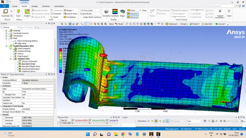
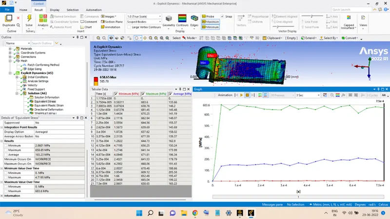
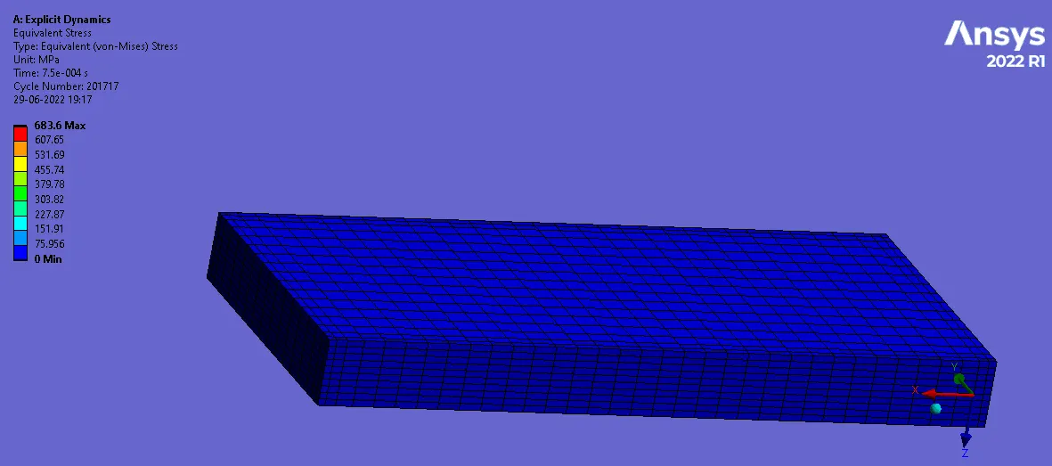
The variation of the stress during the operation is shown in the above figures. The maximum stress value reached is equal to 683.6 MPa. The TOOL this time almost reached the end of the WORKPIECE length with the increased speed. The stress variation, for this case, is not uniform and is seen to fluctuate.
For this speed, there are plenty of elements that got separated from the main WORKPIECE body, implying that the operation was fast and rigorous.
Deformation along X-Axis:
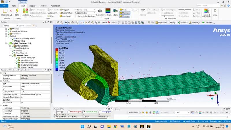
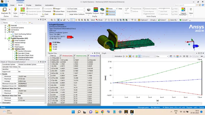
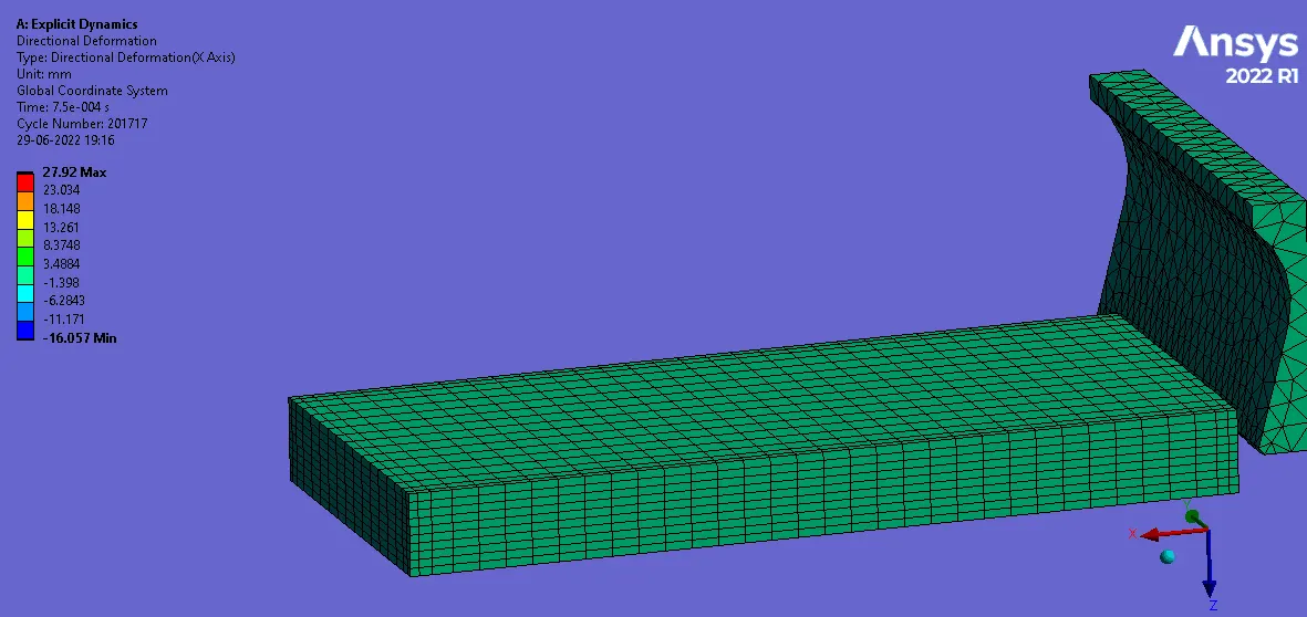
Variation of the deformation experienced by WORKPIECE during the operation is shown in the figures above, the maximum deformation is equal to 27.92 mm.
For this speed, in the later stages, the TOOL sheared off the entire width of WORKPIECE, as seen in the figure, implying that the operating speed is too much.
Temperature:
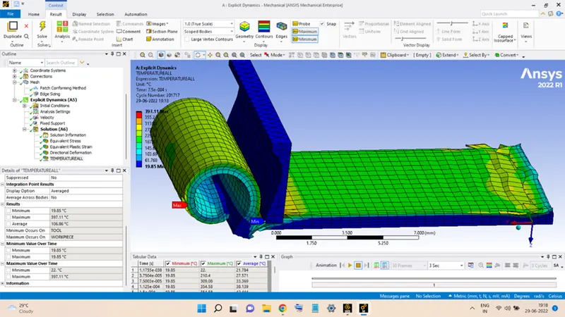
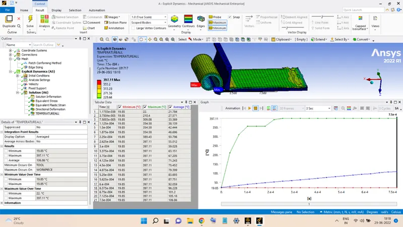
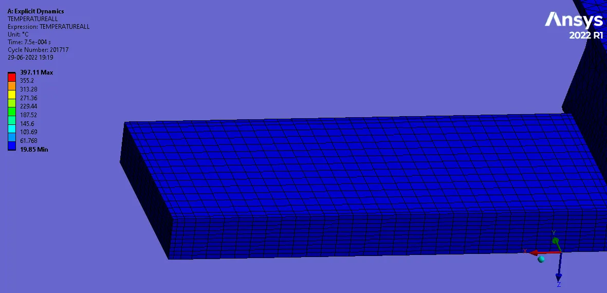
The temperature of WORKPIECE during the operation can be seen from the above figures, it maximum value is equal to 397.11oC which occurs during the later part of the operation.
The variation of temperature is also seen to increase during the early stages and is maintained uniform for the rest of it.
CONCLUSION:
From the results of both the cases, it can be said that:
The velocity in the first case is providing smooth operating conditions and appropriate cutting action throughout the operation. So, it is advisable to perform the operation with velocity nearby this value.
On the other hand, the velocity in the second case was too much damaging, the elements were sheared off from the main body, the temperature was also excessively high and the cutting operation was also not uniform throughout the operation. Hence, this cutting velocity must be avoided.