Week 9-Creation of 1D Connectors Challenge
MESHING AND CREATING THE CONNECTORS FOR GIVEN MODEL
Objective: To create the connectors after meshing the model with given mesh size and attaching the various connector parts of the given model.
About
Connectors are used to join the geometry, component and elements to transfer the load from one location to the other. There are many connector types available like 1D, 2D and 3D connectors. Connector panels and modules are almost similar in 1D, 2D and 3D.basically depends on type joint and joint strength.
In our model the CAD model is middle surface here so no need to extract the middle surface again
File (type) > Import > geometry or CAD model > select the link and click on import
While Import the CAD model file (step , hm or IGES etc.) the model may have geometrical errors like unconnected, missing and duplicate surfaces also overlap surfaces due to small geometry areas in the model. Cleanup operations include the equivalence of "red" free edges, fixing of small surfaces (relative to the element size), and detection of features such as beads. It also performs specified surface editing or de-featuring operations like the removal of pinholes (less than specified size), removal of edge fillets, and the addition of a layer of washer elements around holes
Model imported
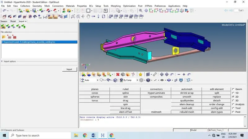
Auto cleanup: After extracting middle surface we need to clean the geometry .To use auto cleanup the geometry before meshing the model as per the criteria given... Below we can observe the CAD model with missing surfaces, sometime these are done by auto cleanup or manually we have to clean the geometry as well as middle surface.
Geometry > auto cleanup> enter the target elemental length > select the model > click on auto cleanup
Manual cleanup: Sometimes we need to clean the geometry manually where auto cleanup not works properly.
Meshing: Creating the mesh on 2D surface using auto mesh option here. Before we create the meshing we need to edit he criteria by using F12 in the keyboard or preference > criteria, parameters. Here we consider only element size, maximum and minimum sizes only.
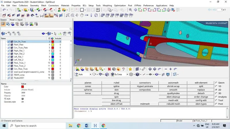
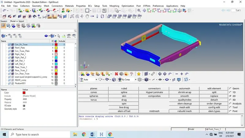
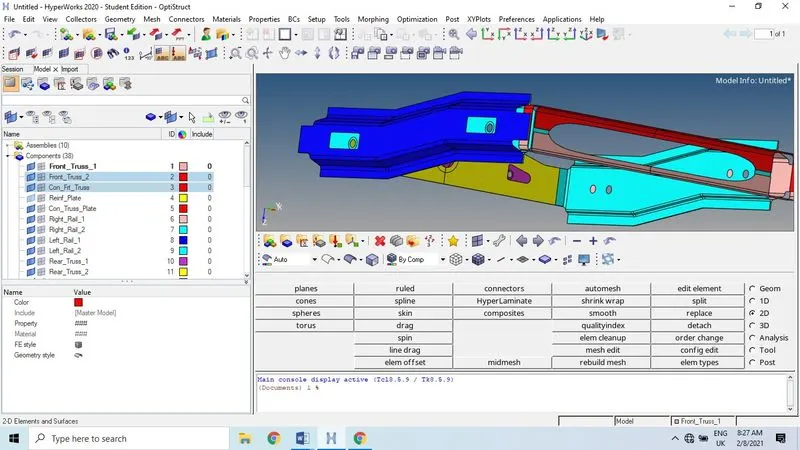
Size and Bias.
Use the Size and Bias subpanel to perform size and bias meshing, a flexible and powerful meshing method. A minimum of inputs are required for the element criteria settings.
Size and biasing meshing produces a mesh with consistent element size. If meshed interactively, the number of elements (element density) node spacing (biasing), element type and mesh style can be modified for each surface face and edge.
Use the Auto mesh panel to generate a mesh of plate elements using surface geometry or existing shell elements to define the mesh area.
I have used mixed elements instead quad and other elements available.
Uses quads primarily, but inserts trias when making density transitions, resulting in improved mesh quality. I have used mixed elements here to improve the mesh quality and it’s easy to work on surface mesh.
Set the options in the panel in any order that you feel comfortable using. Moving from subpanel to subpanel will not cause you to lose work. When you are finished making all your selections, click mesh to start the meshing process.
Right_Rail_2 & Front_truss_1: Seam-Quad (angled+capped+L)
Overview of the structure in the Spot, Bolt, Seam and Area panels.
All panels subdivided in at least three subpanels:
Spot/bolt/seam/area: The connector of the appropriate type is both created and realized simultaneously.
Create: The connector of the appropriate type is only created.
Realize: An existing connector of the appropriate type is only realized.
Right_Rail_2 & Front_truss_1: Seam-Quad (angled+capped+L).
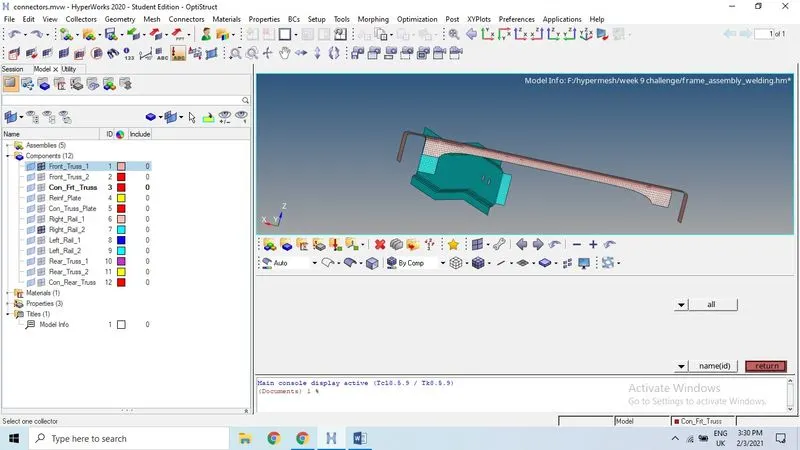
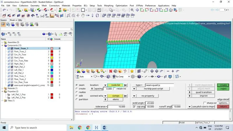
Seam Panel
Use the Seam panel to create connectors that represent line connectors such as seam welds. These connectors can later be realized as standard or custom weld representations.
Reverse direction
During the first realization of a seam its direction is determined. Even though this direction is only important for realization types which use angle information like seam-quad (angled), every seam gets this direction. Therefore the reverse direction checkbox only appears for angled seams.
The direction can only be reversed during the next realization if the checkbox is enabled.
Left_Rail_2 & Front_truss_1:
Connection established here is 2D, 2D > Connector > spot, seam, bolt etc. select seam > seam, create, realize, edit select seam here and select the location as line or node list by drop down button in subpanel.
In the subpanel we can select type of joint as per our criteria given, in the below image we can notice the element type by clicking on dropdown button.
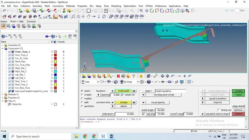
Quad elements -Once the node list selected in subpanel, go to the next drop down button where we need to select the component, assembly, elements and parts. We need to select the number of layer according to the number of components to be joined using the connection
Quad Realization Options
Exclusive options available for seam realization types with a quad row representing the connection. Not all of these settings have to be defined for all quad realization types.
IMAGES copied from Altair website
Welding Angle: Define the distance between the normal projection and the quad direction.
Principally it is allowed to define weld angles between 0.0 and 90.0. If the value is set to 0.0 an internal thickness-based calculation is used. If the value is set to 0.0 and no thickness is defined the connector will fail.If the angle is created in the wrong direction, the seam can be reverted by enabling the reverse direction checkbox and performing a rerelization
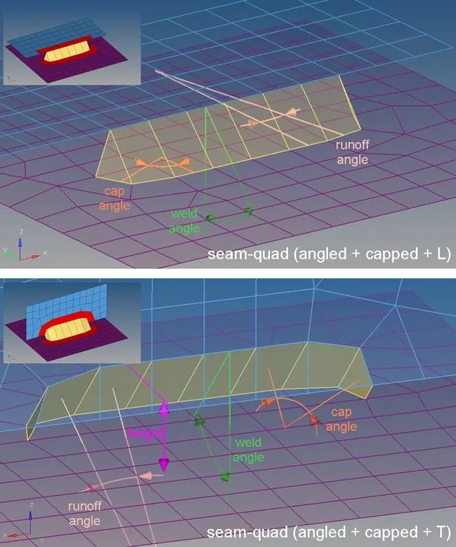
Cap Angle: Measured between the normals of the cap element and the second-to-last element of the seam.
Measured between the edge normal of the cap element and the second-to-last element of the seam in the plane of the opposite link.
Cap angles are created by default. Clear this checkbox to remove cap angles and runoff angles.
Cap angles between 0.0 and 45.0 are permitted, but be aware that larger values can lead to bad elements. The recommended value is 10.0 or smaller. Cap angles between 45.0 and 90.0 are permitted, but be aware that smaller values lead to bad elements. The recommended value is 75.0 and higher.
Runoff angle: Depending on the seam-quad type, the runoff angle is measured differently.
- Measured between the normal of the last and the second-to-last last element of the seam.
- Measured between the edge normal of the last and the second-to-last element of the seam in the plane of the opposite link. Clearing the cap angles checkbox removes runoff angles, which are created by default.
Height Define the distance between the projection point and the start-point of the angled quads. The height needs to be chosen in an extent to bridge the gap between the links. Also, the height strongly influences the quad length, especially in cases of very large weld angles.
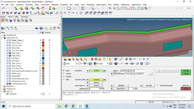
Front_truss_2, Front_truss_1 & Right_Rail_1- Spot weld with 3 Layers and 5 mm Diameter
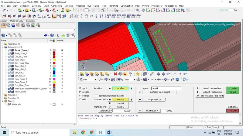
Spot Panel: Use the Spot panel to create connectors that represent point connectors such as spot welds. These connectors can be realized as standard or custom weld representations.
Select the location of the connector to be created.
Nodes: Select an existing node (also temp nodes).
Points: Select an existing point (fixed point or free point).
Node list: Select a node list and specify spacing or density and end offset.
The selected nodes are used to internally create a smoothed line, which is used exactly as a real line. The connector will not remember the position of the selected nodes, unless you select the preserve nodes check box.
Lines: Select a line and specify spacing or density and end offset
Connect what: Select the entities to become link candidates. Link candidates are certain entities of a chosen link type, which are supposed to be connected during the realization. Entities outside the tolerance are not taken into account.
Component: Select components to be added as link entities. You can choose to connect to either the geometry or elements of the selected components.
Assembly: Select assemblies to be added as link entities. You can choose to connect to either the geometry or elements of the selected assemblies.
Surfaces: Select surfaces to be added as link entities. You can choose to connect to either the geometric surfaces or elements associated to the selected surfaces.
Elements: Select elements to be added as link entities.
Nodes: Select nodes to be added as link entities.
Tags: Select tags to be added as link entities
Front_truss_2, Front_truss_1 & Left_Rail_1- Hexa (Adhesive)
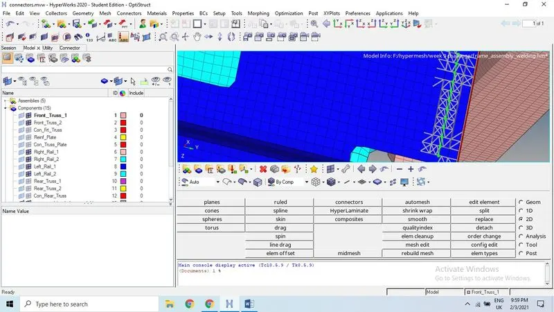
Rear truss 2 & Right Rail2: Bolt Connector
Rear truss2 & Left Rail 2: Bolt Connector
Bolt Panel: Use the Bolt panel to create connectors which will be represented as a 1D element construct
Define how many thicknesses (layers) have to be connected at the connector position.
When link detection is performed the valid connector links are established with respect to the given tolerance and the selected link candidates. By default the links are reduced to the minimum needed. The number of links is typically higher than the number of layers, because a valid pair of projections need to be found per test point.
Tolerance
The tolerance used during the realization process is always written to the connector.
This approach is the same for all connector types. For most of the bolt realization types the approach is the same, though further requirements like holes of certain diameters on the links might be required for a successful realization?
Number of layers: Define how many thicknesses (layers) have to be connected at the connector position.
When link detection is performed the valid connector links are established with respect to the given tolerance and the selected link candidates. By default the links are reduced to the minimum needed.
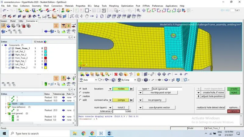
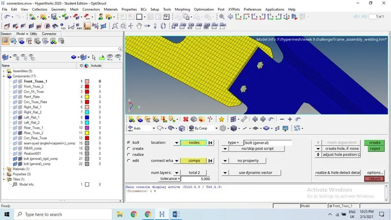
Right_Rail_1 & Right_Rail_2- Spot-weld with Rigid Elements
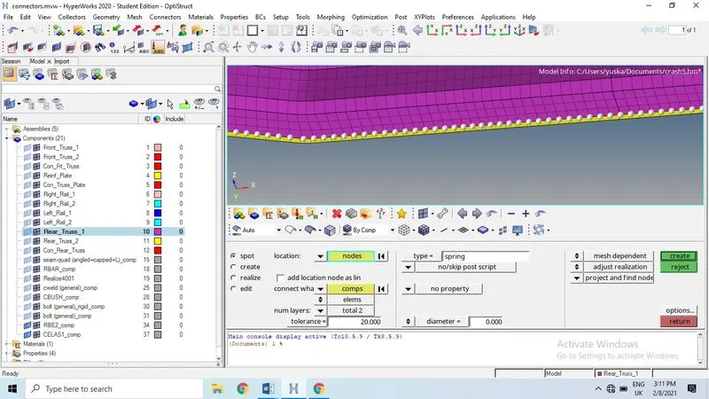
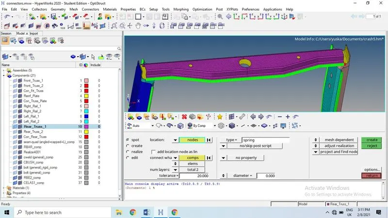
Left_Rail_1 & Left_Rail_2-Spot-weld with Spring Elements
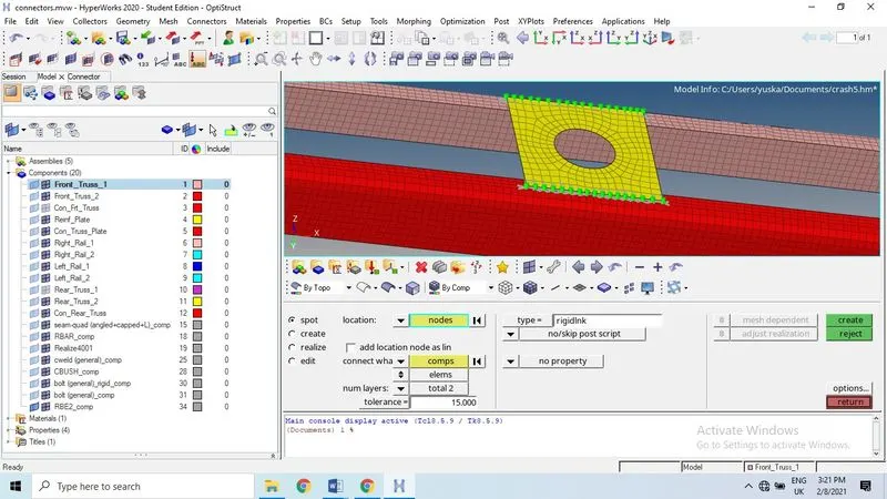
Spot weld using spring type
Both connections are similar type of connections but the only change is type of spot weld, one is rigid and other one is spring elements.
This is spot weld with spring type: Before we create the connection make sure to select current components.
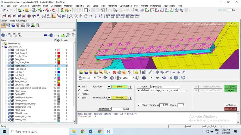
Area Panel
Area> lines, elements, nodes and line list (select the elements on both components > click on component
Use the connector Area panel to create connectors that represent connections of larger regions, such as adhesives. These connectors can later be realized as standard or custom weld representations.
The test points of an area connector are characterized by nodes of an internal mesh dedicated to the connector. During connector creation the internal mesh can be created by adopting the mesh used for location, or the defined region is auto meshed with a certain mesh type.
When the Area panel is active, only area-type connectors display in the modeling window; graphics for other connector types are suppressed until you exit the panel.
Apply Mass Panel
Use the Apply Mass panel to create a dummy connector entity to add mass to a part, or create areas of mass to represent parts not present in the CAD or FE data.
The Apply Mass panel does not create a physical join connection. Instead, the connector entity is used to distribute mass to nodes or elements.
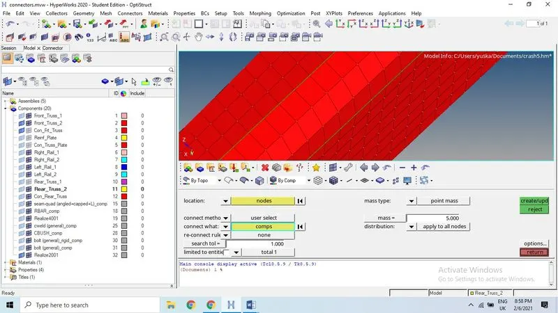
Select the any node the face of the component then select the by face or by displayed. Before selecting the create button assign the mass value and select the mass type as the list mentioned at mass type dropdown button.
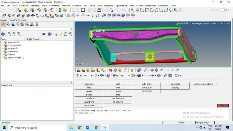
Final image with connections:
Outcomes
- Learned to create various connections like seam, spot and bolt.
- Understand the necessary connection types required in various locations of the model.
- Learned how to create connection less errors in the mesh pattern.
Conclusion: Created 2D connectors as per the given connection types after meshing the middle surface of the CAD model using hypermesh