Week 9-Creation of 1D Connectors Challenge
AIM:- Meshing of the given geometry. Provided below are the quality parameters that you have to follow.
Target Element size = 5 Units
|
S.N |
Quality Criteria |
Value |
|
1 |
Aspect Ratio |
5 |
|
2 |
Skewness |
45 |
|
3 |
Warping |
15 |
|
4 |
Taper |
0.5 |
|
5 |
Min. Length |
2 Units |
|
6 |
Max. Length |
8 Units |
|
7 |
Min angle Quad |
45 |
|
8 |
Max angle Quad |
135 |
|
9 |
Min angle Tria |
30 |
|
10 |
Max angle Tria |
110 |
|
10 |
Tria % |
15 |
Create connector and Attach the various parts of the given model
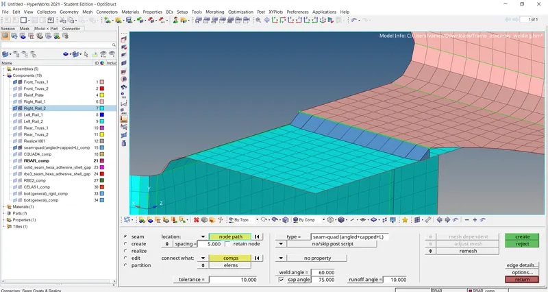
1. Right_Rail_2 & Front_truss_1:- Seam-Quad(angled+capped+L)
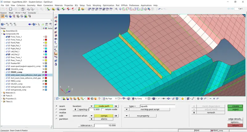
2. Left_Rail_2 & Front_truss_1:- Quad elements
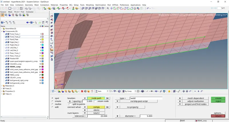
3. Front_truss_2, Front_truss_1 & Right_Rail_1:- Spot weld with 2 Layers and 5 mm Diameter
4. Front_truss_2, Front_truss_1 & Left_Rail_1:- Hexa (Adhesive)
5. Rear_truss_2 & Right_Rail_2:- Bolt Connector
6. Rear_truss_2 & Left_Rail_2:- Bolt Connector
7. Right_Rail_1 & Right_Rail_2:- Spot-weld with Rigid Elements
8. Left_Rail_1 & Left_Rail_2:- Spot-weld with Spring Elements
9. Rest all the component left Join them with suitable connectors
Objective:-
The objective is to generate the mesh on the given model by following the Quality criteria and creating the connectors and attach the various parts of the given model.
CAD Model Images:-
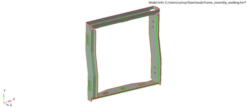
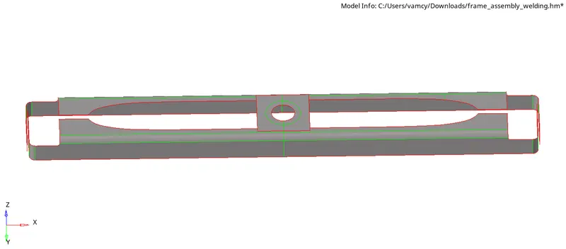
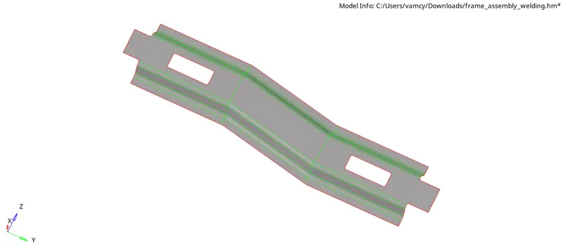
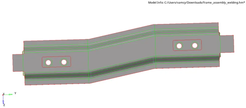
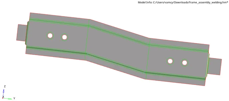
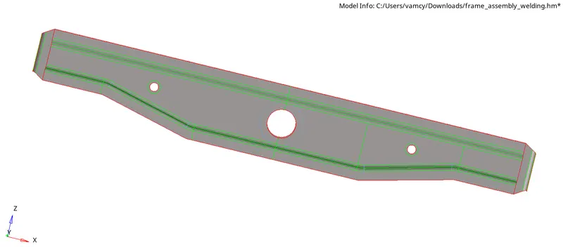
Procedure:-
1. Importing the Model
2. 2D Meshing
3. Creating Connectors
1. Importing the model:-
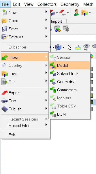
- At first we need to Import the Model File>>Import>>Model>>Select the model>>Import.
2D Meshing:-
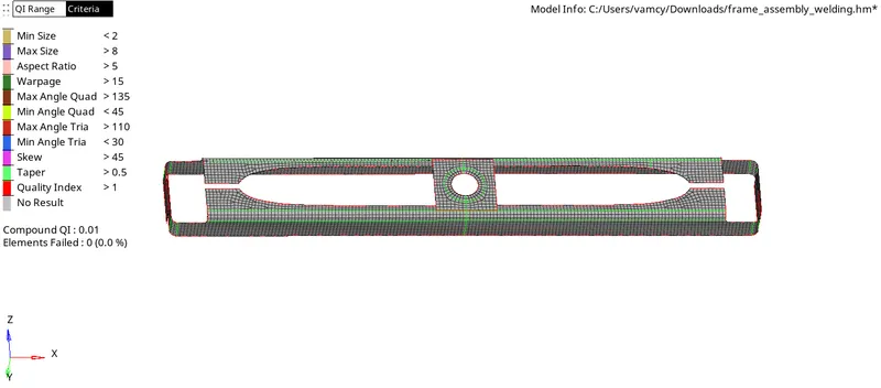
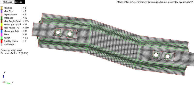
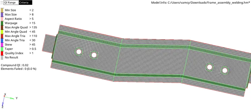
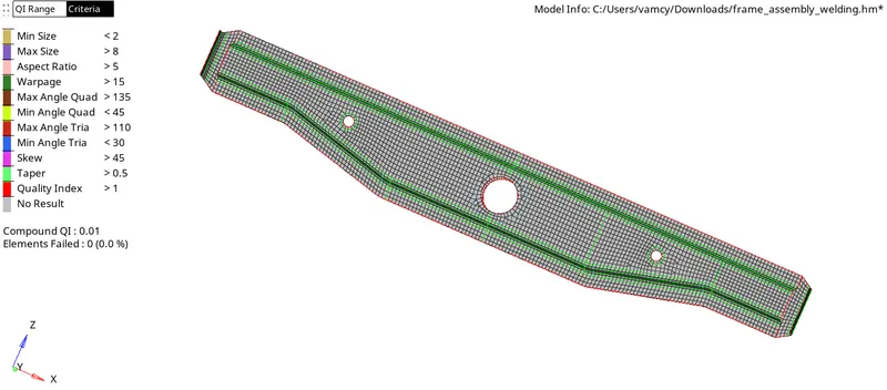
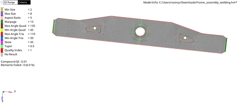
- To generate mesh go to 2D>>automesh>>Element size=5>>mesh type Mixed>>Select the surface>>mesh.
- To get a proper flow edit the mesh by selecting the elements and click on mesh.
- If any element is failing for Quality criteriia Then we can use the cleanup tools in qualityindex and we can use translate tool on some areas.
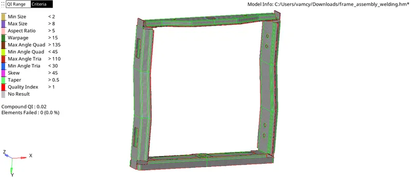
Note:- In the meshing process i have divided the geometry in to half according to the symmetry in the geometry and generated a mesh then reflected the surfaces and elements by duplicating them using reflect tool.
3. Creating Connectors:-
1. Seam Weld connections:-
- Hide all the components expect Right Rail 2 & Front Truss 1.
- 2D<Connectors<Seam<Type=Seam-Quad(angled+capped+L).
- Select the node list and give Spacing value as 5.
- Select the components and give tolerance value as 10 click create.
- Remesh the required areas for proper mesh flow.
2. Quad elements:-
- Hide all the components expect Left Rail 2 & Front Truss 1.
- 2D<Connectors<Seam<Type=Quad.
- Select the node list and give Spacing value as 5.
- Select the components and give tolerance value as 10 click create.
- Remesh the required areas for proper mesh flow.
3. Spot Weld:-
- Hide all the components expect Front Truss 2 & Front Truss 1 & Right Rail 1.
- 2D<Connectors<Spot<Type=Weld.
- Select the node list and give Spacing value as 5.
- Select the components and give tolerance value as 20 click create.
- Select the number of layers as 2 and diameter as 5.
- Remesh the required areas for proper mesh flow.
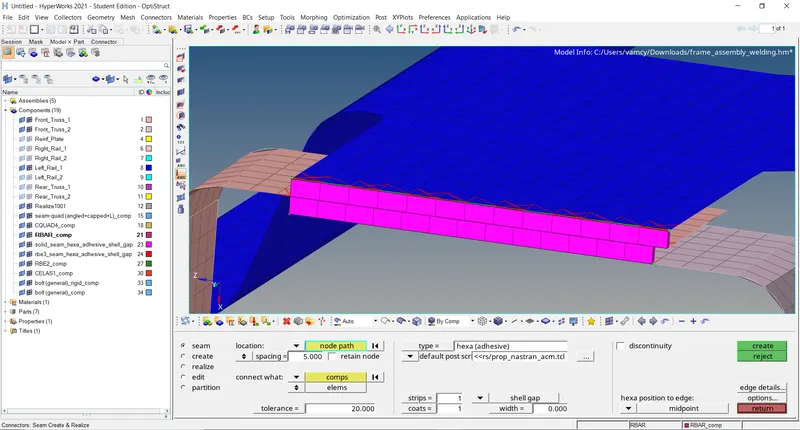
4. Hexa (Adhesive):-
- Hide all the components expect Front Truss 2 & Front Truss 1 & Left Rail 1.
- 2D<Connectors<Seam<Type=Hexa (Adhesive).
- Select the node list and give Spacing value as 5.
- Select the components and give tolerance value as 20 click create.
- Remesh the required areas for proper mesh flow.
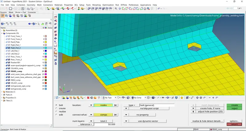
5. Bolt Connector:-
- Hide all the components expect Right Rail 2 & Rear Truss 2.
- 2D<Connectors<bolt<Type=bolt(general).
- Select the node list.
- Select the components and give tolerance value as 50 click create.
- Remesh the required areas for proper mesh flow.
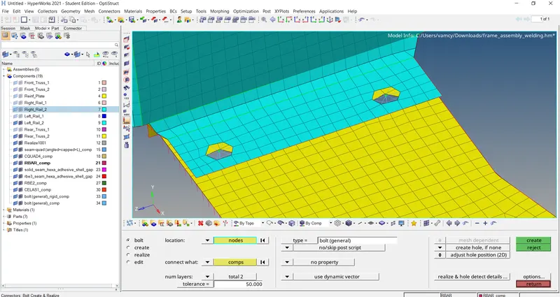
6. Similar steps for bolt connector repeat the same for Rear Truss 2 & Left Rail 2.
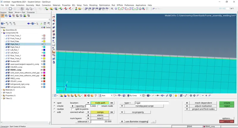
7. Spot Weld with Rigid elements:-
- Hide all the components expect Right Rail 1 & Right Rail 2.
- 2D<Connectors<Spot<Type=Rigid.
- Select the node list and give Spacing value as 5.
- Select the components and give tolerance value as 20 click create.
- Remesh the required areas for proper mesh flow.
8. Spot Weld with Spring elements:-
- Hide all the components expect Left Rail 1 & Left Rail 2.
- 2D<Connectors<Spot<Type=Spring.
- Select the node list and give Spacing value as 5.
- Select the components and give tolerance value as 20 click create.
- Remesh the required areas for proper mesh flow.

9. Remaining components are connected using Spot Weld and Seam Welds by following the above mentioned steps.
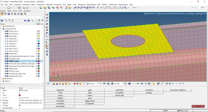
Result:-
Hence generating the mesh on the given model by following the Quality criteria and creating the connectors and attach the various parts of the given model has obtained.
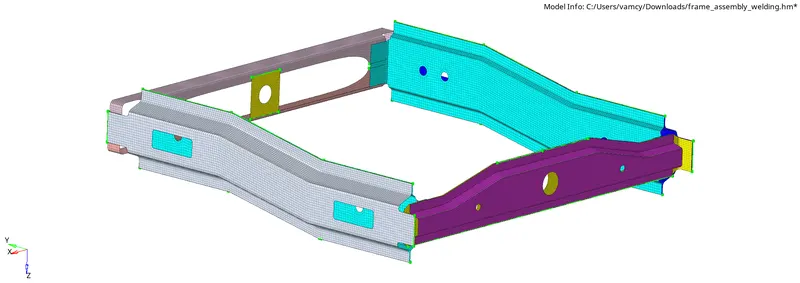
Final Model Image:-
Conclusion:-
- The Frame assembly is Meshed.
- Connections are represented as specified.
- Remaining components are connected using spot and seam welds