Week 9-Creation of 1D Connectors Challenge
AIM: - MESH THE GIVEN GEOMETRY WITH THE GIVEN QUALITY CRITERIA AND CREATE CONNECTORS AND ATTACH THE VARIOUS PARTS OF THE GIVEN MODEL AS MENTIONED.
Objectives:
1. Obtain the 2D mesh of the given geometry.
2. Create connectors and attach the parts using the below-mentioned elements:
a) Front_Truss_1 & Right_Rail_2: Seam Weld (Angled+capped+L).
b) Front_Truss_1 & Left_Rail_2: Quad Elements.
c) Front_Truss_1, Front_Truss_2 & Right_Rail_1: Spot Weld with 2 layers and 5 mm Diameter.
d) Front_Truss_1, Front_Truss_2 & Left_Rail_1: Hexa (Adhesive)
e) Rear_Truss_2 & Right_Rail_2: Bolt Connector.
f) Rear_Truss_2 & Left_Rail_2: Bolt Connector.
g) Right_Rail_1 & Right_Rail_2: Spot Weld with Rigid Elements.
h) Left_Rail_1 & Left_Rail_2: Spot Weld with Spring Elements.
i) Rest all the components left, and join them with suitable connectors.
The given challenge is done using Hypermesh with Optistruct as the profile.
The model, provided as .hm file, was imported into the Hypermesh environment and the given geometry of the frame can be seen in the figure below.
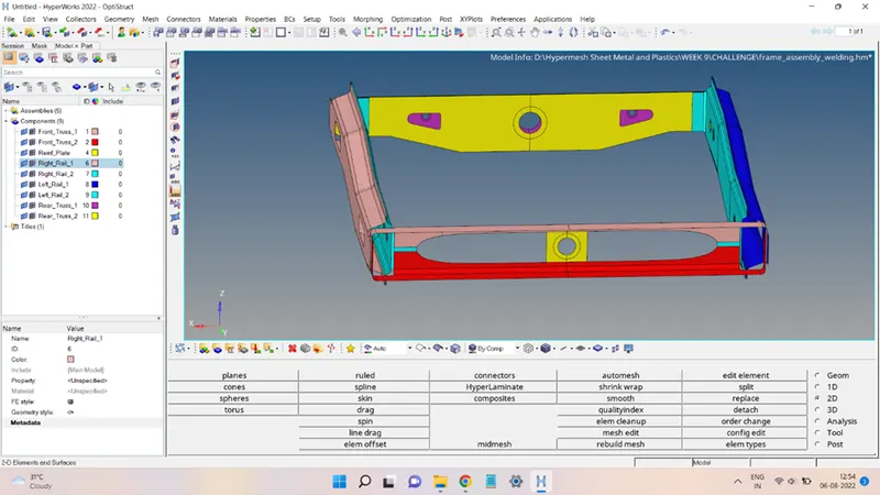
All the different parts of the frame assembly were saved in separate collectors as shown in the above figure.
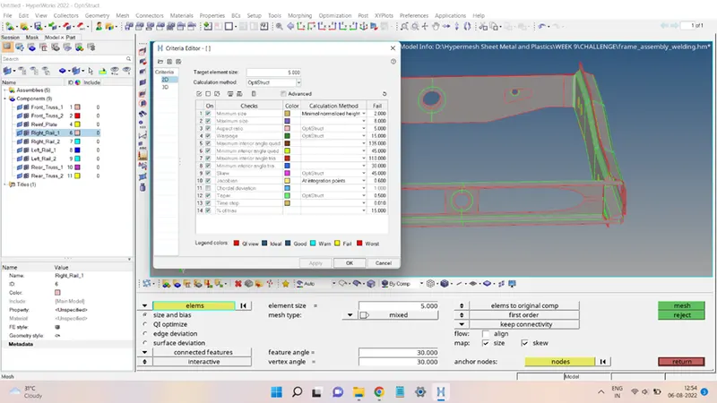
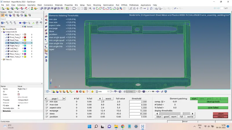
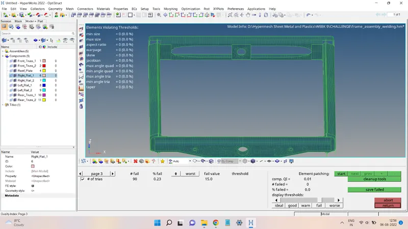
The given geometry meshed with 2D elements, the quality criteria file for the mesh is shown in the figure below:
After meshing and performing the mesh clean-up, the mesh looks like this:
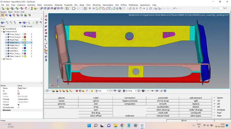
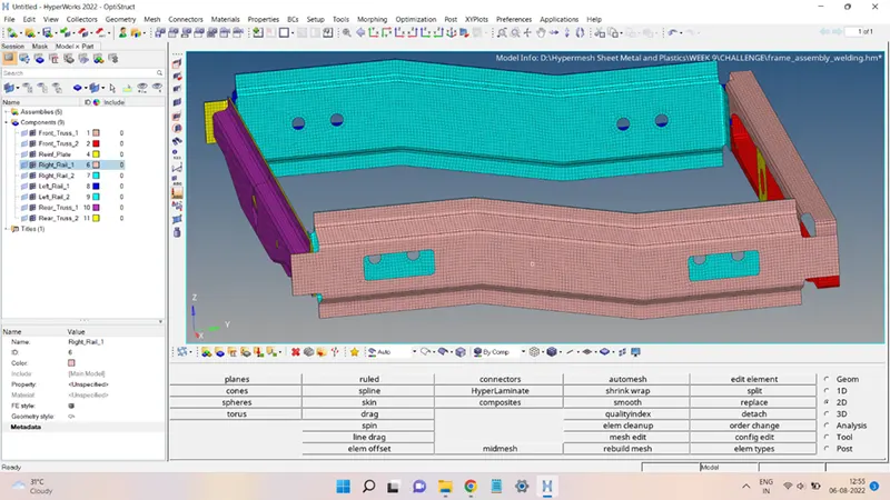
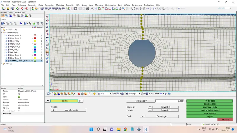
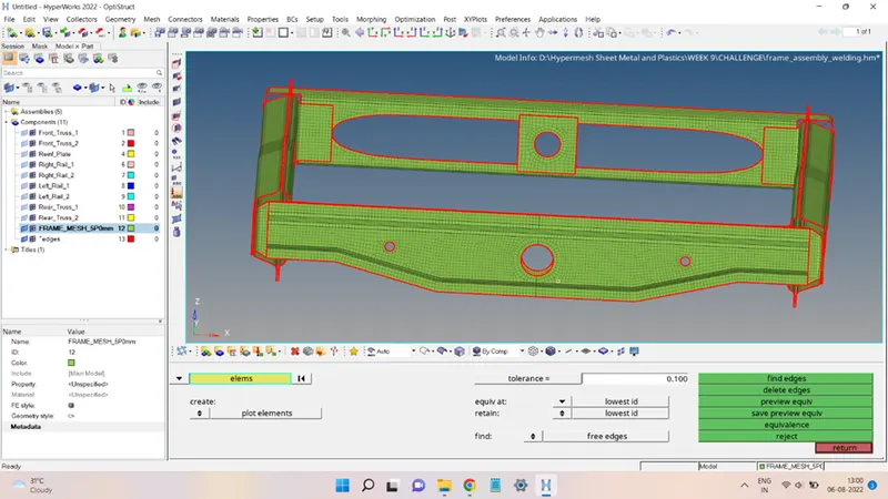
The mesh was checked for the unwanted free edges:
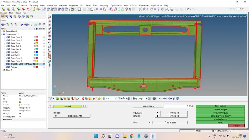
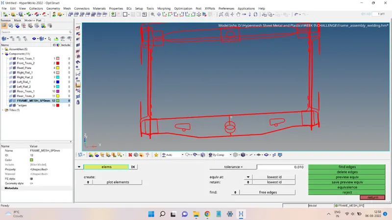
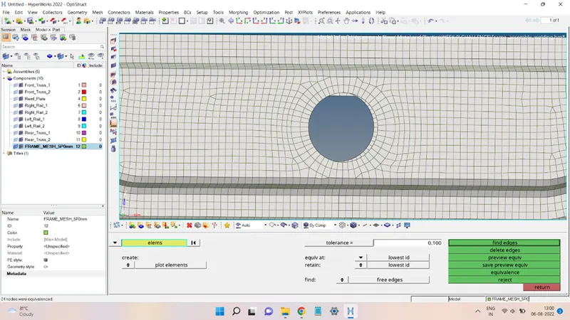
The free edge in the center was eliminated using the Equivalence command and the mesh after it can be seen in the figures shown below.
After the mesh generation, the next step is to add the given connectors to the mesh. All the given connectors were added to the mesh according to the following procedure.
1. Front_Truss_1 & Right_Rail_2: Seam Weld (Angled+capped+L)
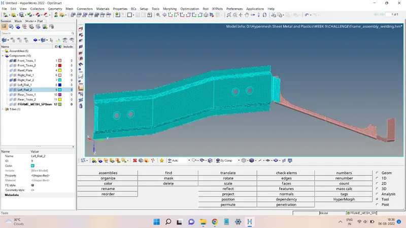
The two parts, namely, Front_Truss_1 and Right_Rail_2 are shown in the below figure.
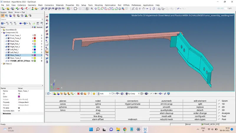
The mesh of the two parts is shown below:
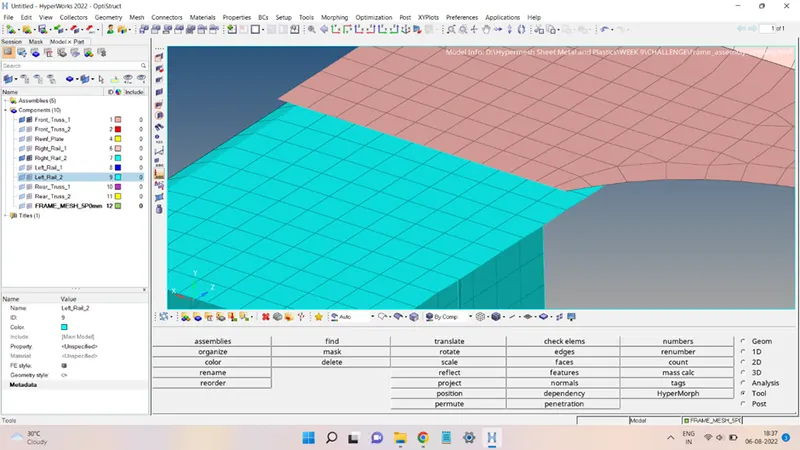
The two meshes will be joined with a connector at the location shown below:
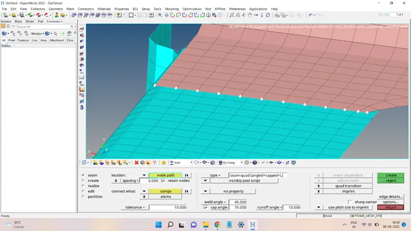
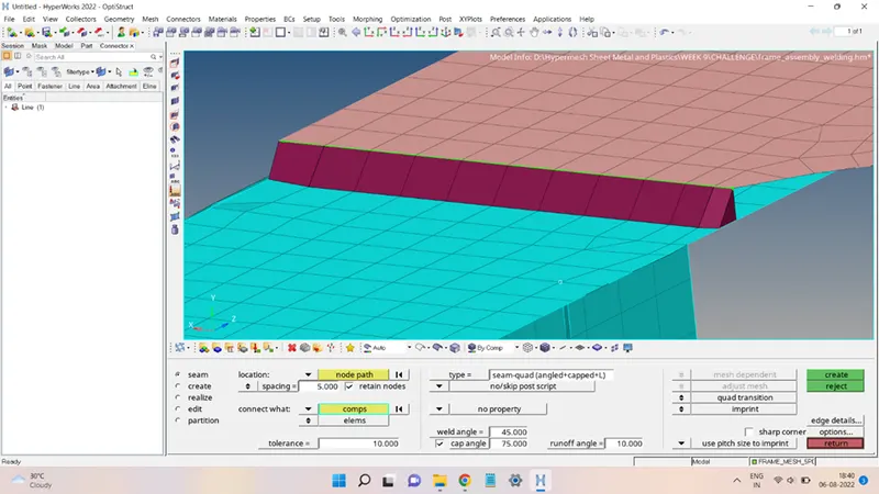
To add the connector, first, click on 2D and select the Connector to open the connector panel. In this panel, select the Seam option and choose the following options to set up the Seam Weld (Angled + Capped + L):
Location = Node path (select the nodes that are to be welded)
Spacing = 5 units; check the retain nodes.
Type = seam-quad(angled+capped+L)
Connect what = add the involved components
Weld angle = 45
Tolerance = 10
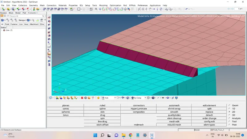
Then click on create to generate the weld.
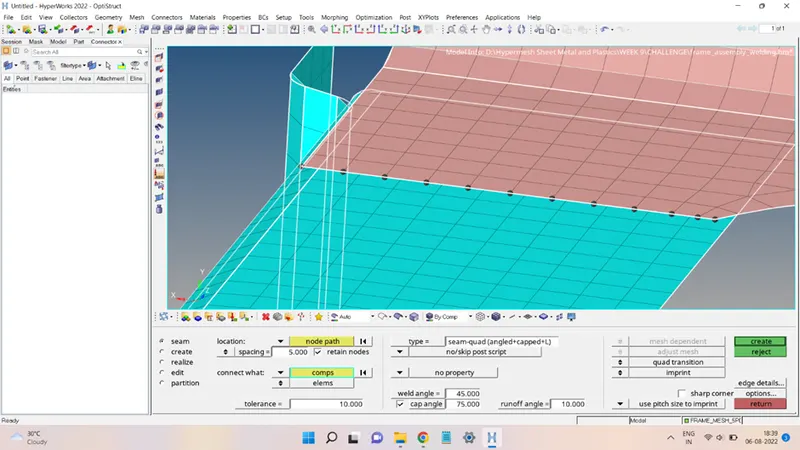
2. Front_Truss_1 & Left_Rail_2: Quad Elements
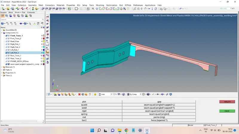
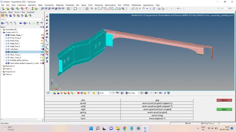
The mesh and surfaces of the two parts that are to be connected with the given connector are shown below:
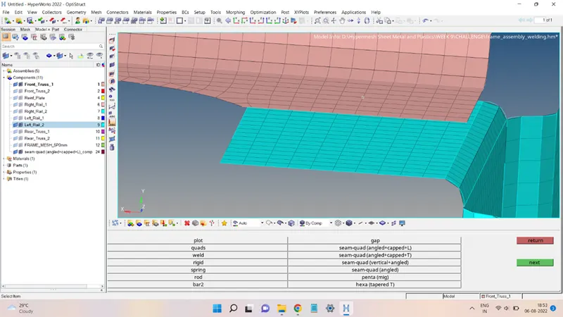
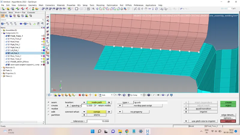
To create the connector, the process followed is:
Select the nodes to be welded.
Spacing = 5 units; check the retain nodes.
Type = quads
Connect what = add the involved components
Tolerance = 10
Then click on create to generate the weld.
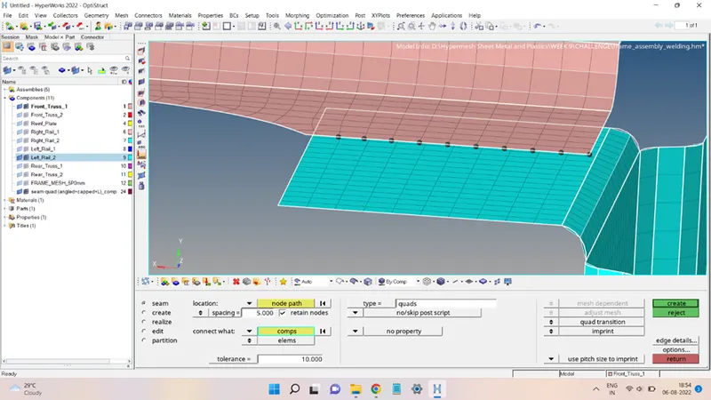
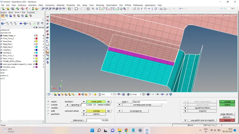
The mesh region near the weld was distorted and must be cleaned up, the mesh after the clean-up looks like this:
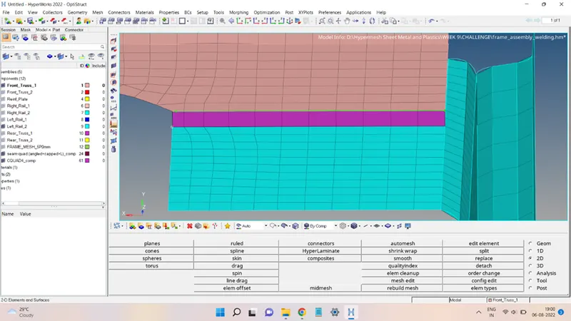
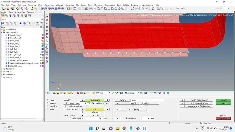
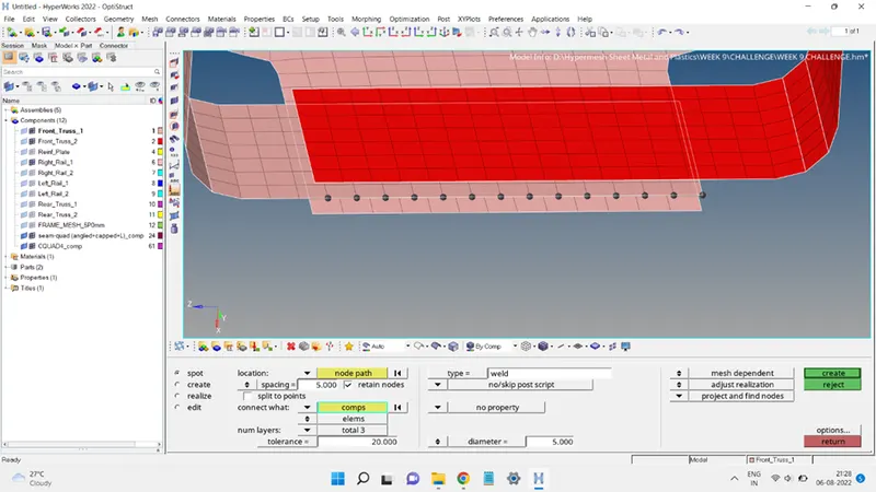
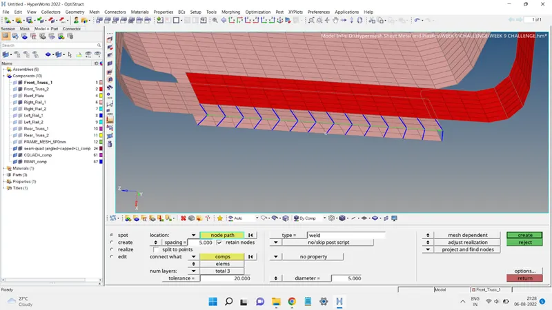
3. Front_Truss_1, Front_Truss_2 & Right_Rail_1: Spot Weld with 2 layers and 5 mm Diameter
The surfaces to be connected and the respective elements are shown below:
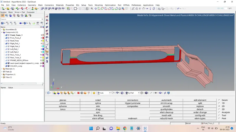
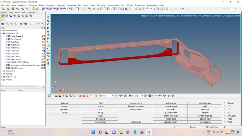
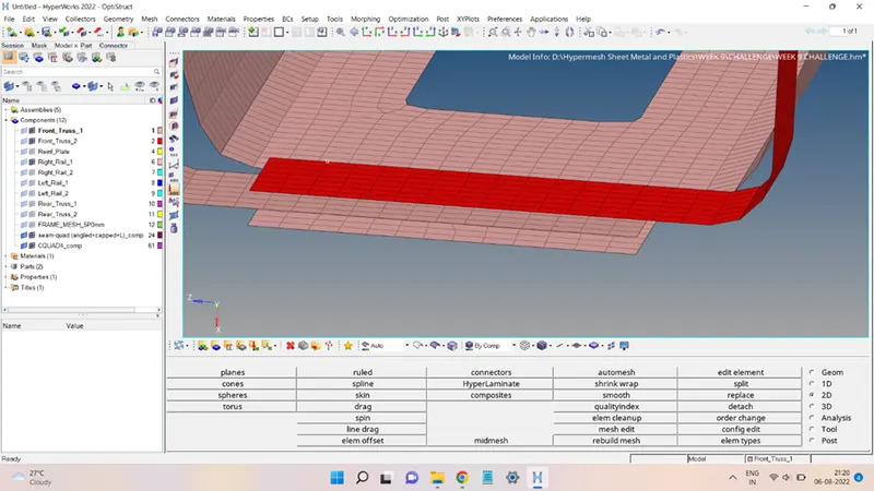
The procedure to add a connector is as follows:
Select the Spot option from the connector panel.
Type = weld
Spacing = 5 units
Connect what = add the three surfaces to be connected
Num layers = 3
Tolerance = 20
Diameter = 5 units
Click on create to add the connector, as shown below:
4. Front_Truss_1, Front_Truss_2 & Left_Rail_1: Hexa (Adhesive)
The surfaces and elements are shown below:
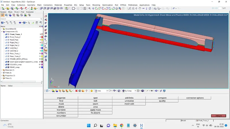
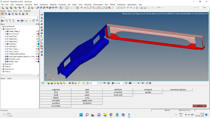
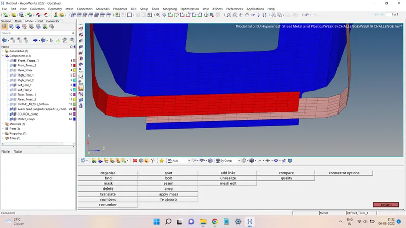
The process to setup the Hexa (Adhesive):
Type = Hexa (Adhesive)
Spacing = 5 units; check the retain nodes option.
Connect what = add the two surfaces to be connected.
Tolerance = 10
Strips = coats = 1
Width = 2 Units
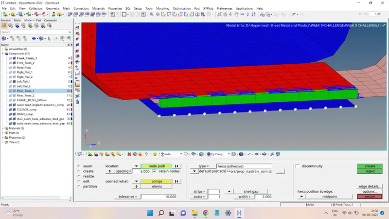
Click on create to obtain the connector, as shown below:
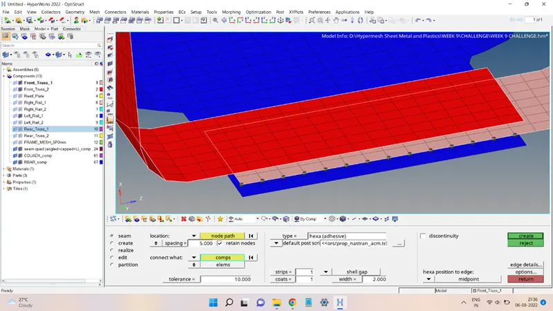
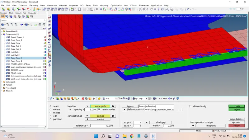
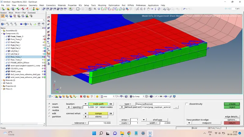
The same is done to obtain the connector between the other two surfaces, as shown below:
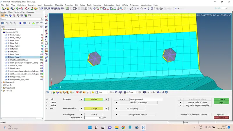
5. Rear_Truss_2 & Right_Rail_2 and Rear_Truss_2 & Left_Rail_2: Bolt Connector
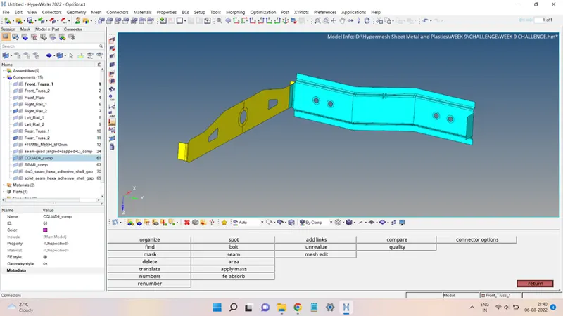
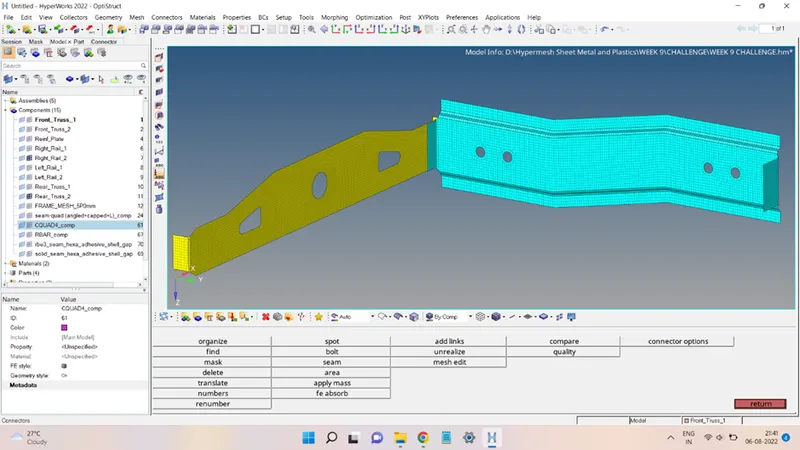
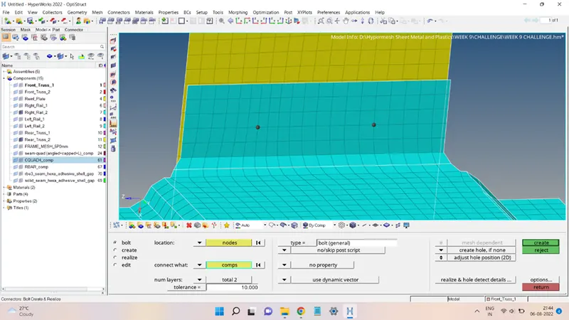
The mesh and the surfaces to e connected are shown below:
Click on Bolt to open up the bolt connector panel, and select the nodes and the components where the bolt is to be added.
Type = bolt (general)
Tolerance = 10
On the right side of the panel, change the 'consider existing holes only' to 'create hole, if none' and click on create to obtain the bolt connector.
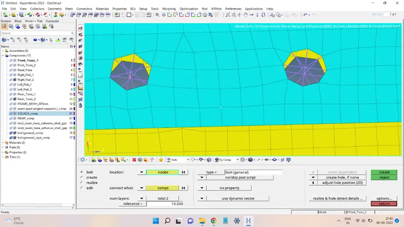
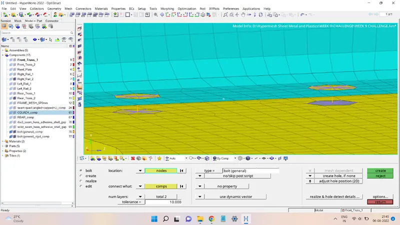
Clean up the distorted mesh near the bolted region.
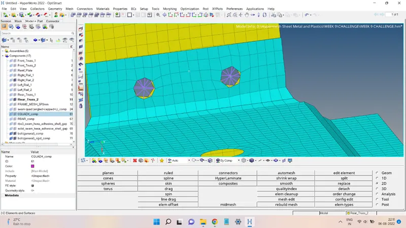
6. Following the same process, the bolt connector was added to the Rear_Truss_2 & Left_Rail_2, as shown below:
7. Right_Rail_1 & Right_Rail_2: Spot Weld with Rigid Elements
The surfaces and the elements to be added with the connector are shown below:
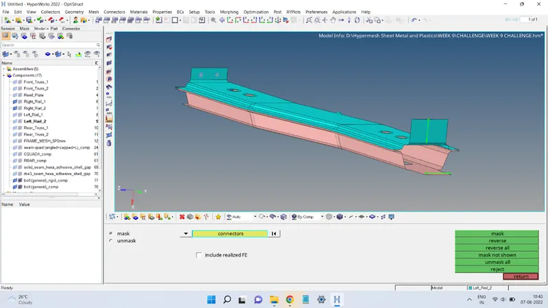
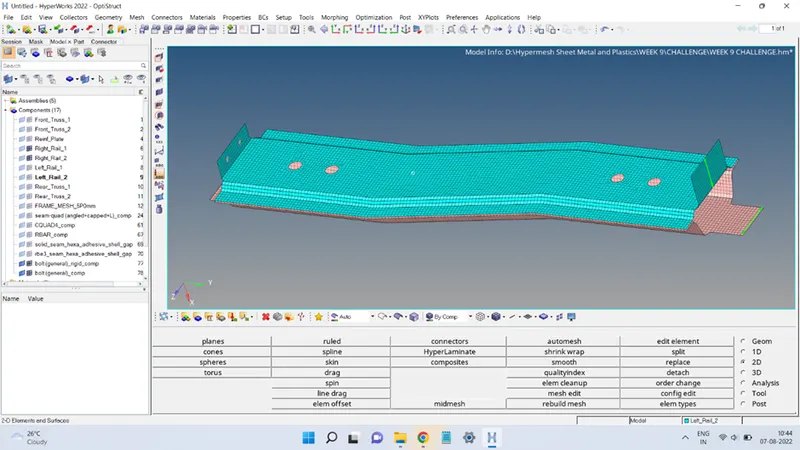
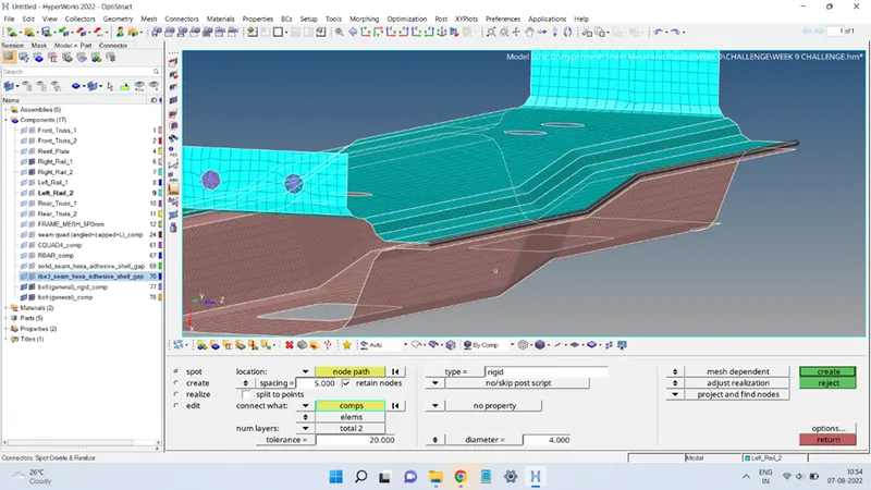
In the connector panel, go to the Spot to open up the spot weld panel. In the spot weld panel, the following were the settings done to create the connector:
Location = select the nodes that are to be spot welded.
Spacing = 5 units; check the retain nodes box.
Connect what = select the components to be spot welded.
Tolerance = 20
Type = Rigid
Diameter = 4 units
Click on create to obtain the connector.
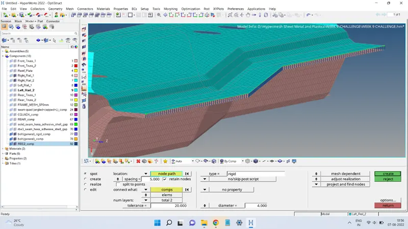
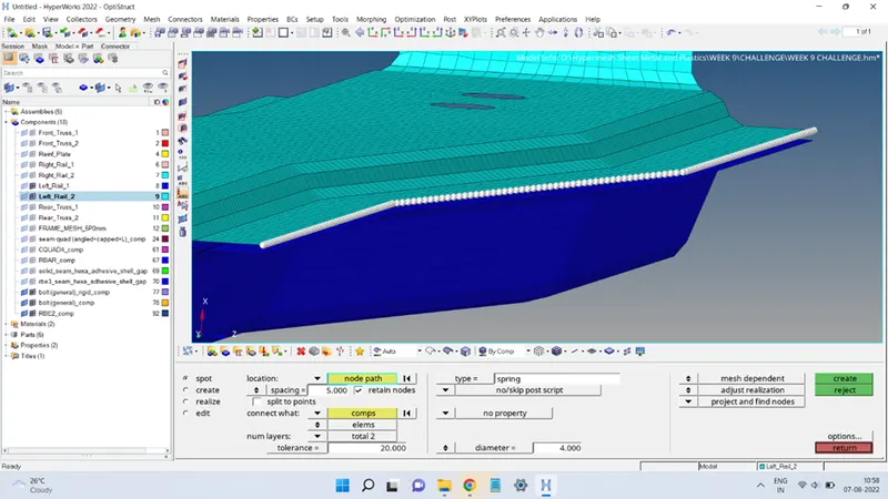
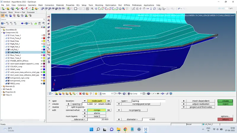
8. Follow the same process to create a Spot weld with Spring elements between the Left_Rail_1 & Left_Rail_2, but in order to have Spring elements, change the type from Rigid to Spring and the rest all are kept as it is, and click on create to obtain the connector.
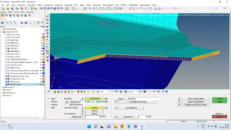
9. Next, the Reinf_Plate component mesh is not connected to any of the other mesh, so to connect it, the seam weld Hexa (adhesive) connector is added between the Reinf_Plate & Front_Truss_1, as shown below:
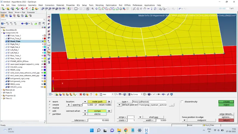
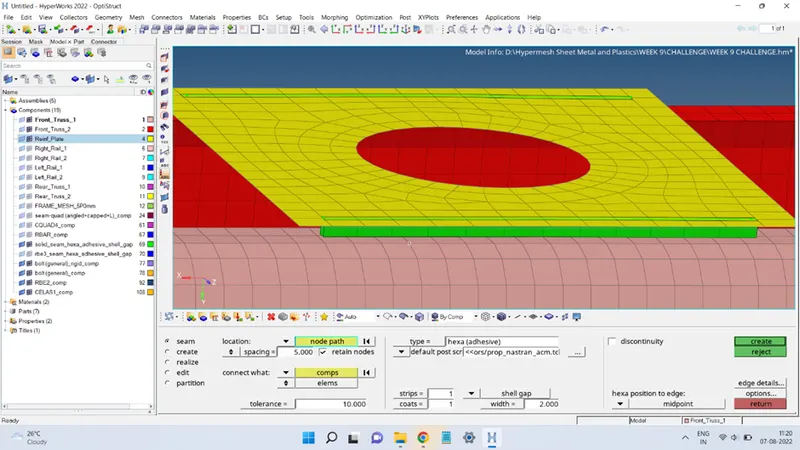
Also, Front_Truss_2 & Left_Rail_2 were connected using seam quad weld, and Front_Truss_2 & Right_Rail_2 were connected using the Hexa (Adhesive) element, as shown below:
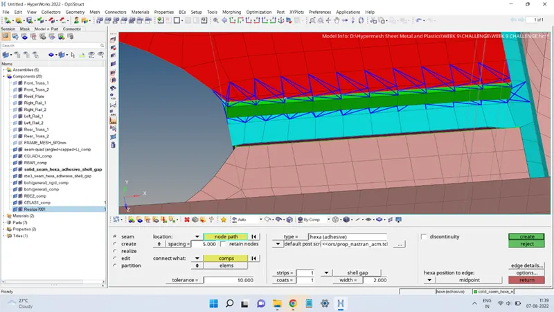
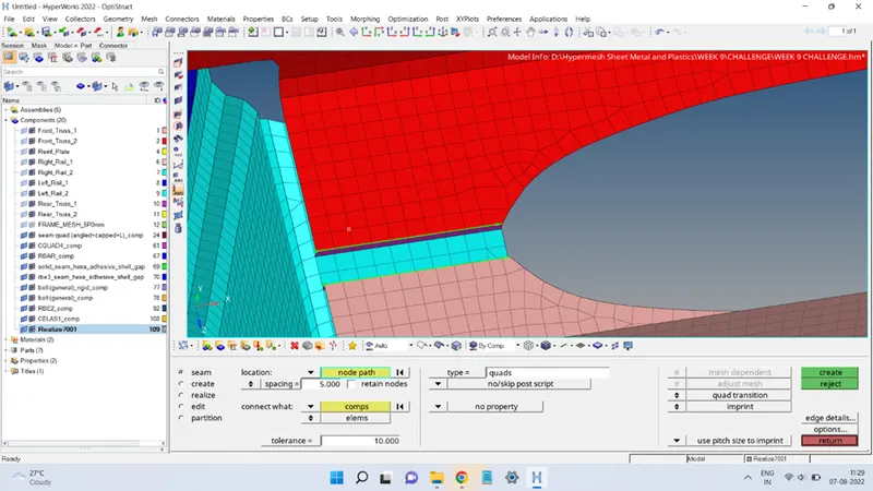
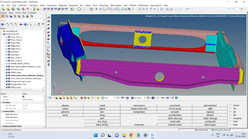
Finally, the mesh after adding all the given connectors will look like this:
Conclusion:
This exercise provided an opportunity to learn the process of adding different connectors to the mesh and how to realize the unrealized connectors.