Creation of 1D Connectors in Hypermesh
OBJECTIVE :
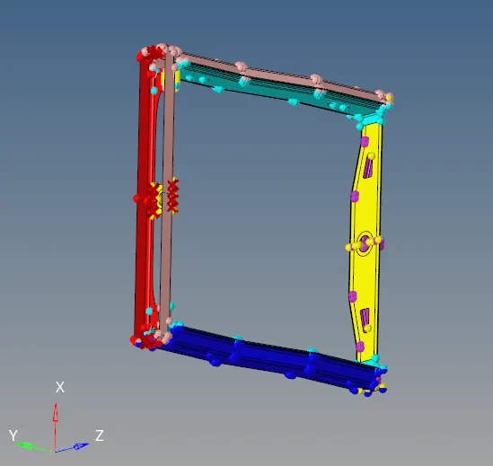
The component given to be connected with below instructions:
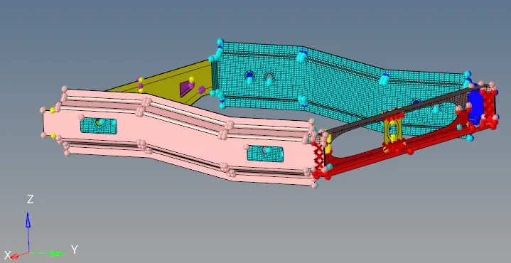
Mesh the given Component with a Mesh size of 5mm.
Create connector and Attach the various parts of the given model
1. Right_Rail_2 & Front_truss_1:- Seam-Quad(angled+capped+L)
2. Left_Rail_2 & Front_truss_1:- Quad elements
3. Front_truss_2, Front_truss_1 & Right_Rail_1:- Spot weld with 3 Layers and 5 mm Diameter
4. Front_truss_2, Front_truss_1 & Left_Rail_1:- Hexa (Adhesive)
5. Rear_truss_2 & Right_Rail_2:- Bolt Connector
6. Rear_truss_2 & Left_Rail_2:- Bolt Connector
7. Right_Rail_1 & Right_Rail_2:- Spot-weld with Rigid Elements
8. Left_Rail_1 & Left_Rail_2:- Spot-weld with Spring Elements
9. Rest all the component left Join them with suitable connectors
COMPONENT:
PROCEDURE :
- Check for topological errors in all the components one by one
- Extract mid surface of the component to be meshed.

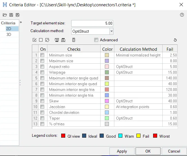
- Set the quality criteria parameter ,
click F10 > Settings > Criteria editor,
MESHING :
Press F12, for automesh > Select Surface
Options to be considered,
- Use Quality index clean up tools to removed meshing re- works.
- Smooth option to smooth the mesh region and align accordingly.
- "Edit element" from geometry to clean up surface and fix up surface issues.
- Key "F6" to create, split, create and combine elements.
- "Shift + F7" is used to align the mesh to the surface/line/plane/vector
- Use "O" key to
keep mesh - Keeps mesh without re arranging other meshed region
Remesh model - Helps in remeshing
Advanced remesh - Equivalences the meshed region nearby when meshed.
- Rebuild mesh to create inbuilt mesh optimizer
- Element clean up if all the method to optimize the element fails.
- Reflect option to mirror the activity.
2D MESHING:
CONNECTORS :
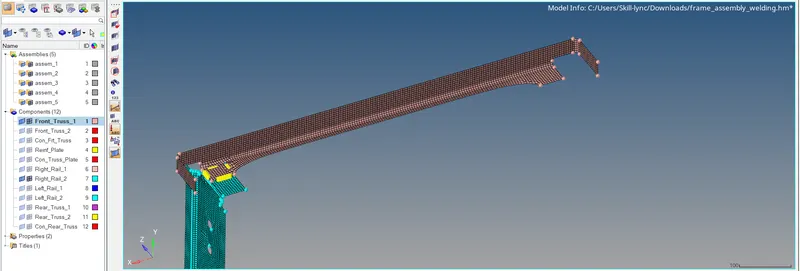
1. Right_Rail_2 & Front_truss_1:- Seam-Quad(angled+capped+L)
3D > Connectors > Seam > Quads > Select Spacing

- Connect the two surfaces, as shown below
2. Left_Rail_2 & Front_truss_1:- Quad elements
3D > Connectors > Seam > Quads

- Connect the two surfaces, as shown below
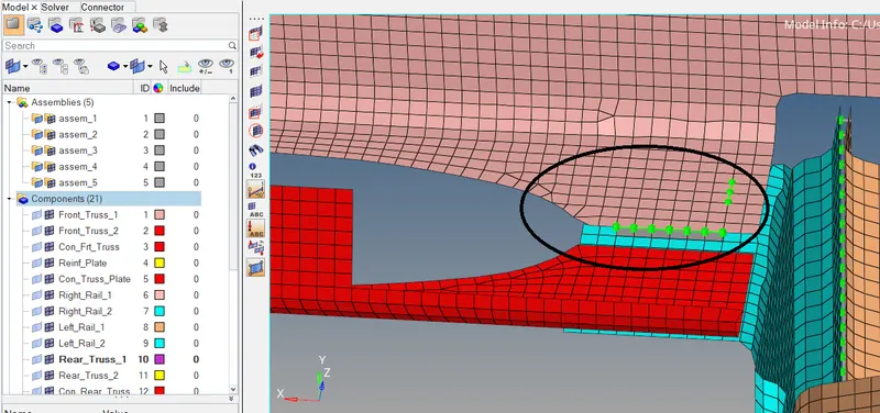
- Make sure the seam quads are realized.
3. Front_truss_2, Front_truss_1 & Right_Rail_1:- Spot weld with 3 Layers and 5 mm Diameter
3D > Connectors > Seam > Quads

- Connect the two surfaces, as shown below
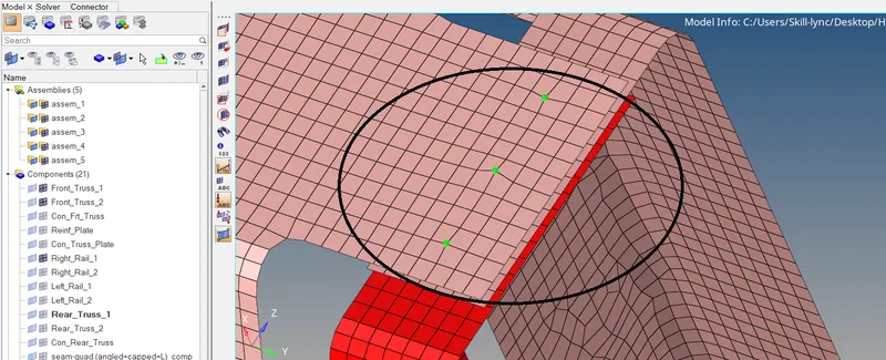
- Make sure the spot welds are realized.
4. Front_truss_2, Front_truss_1 & Left_Rail_1:- Hexa (Adhesive)
3D > Connectors > Area > Adhesives.

- Connect the two surfaces, as shown below
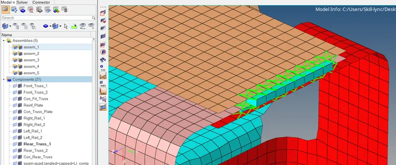
5. Rear_truss_2 & Right_Rail_2:- Bolt Connector
3D > Connectors > Bolt > Bolt General

- The two components are bolted to each other,
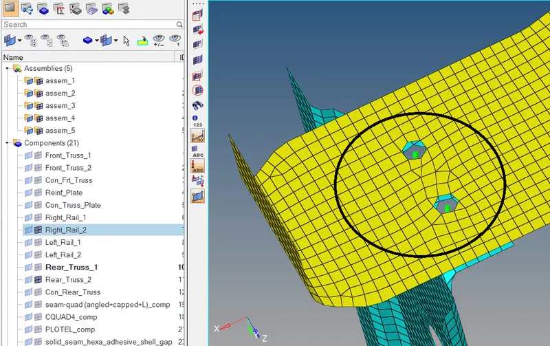
6. Rear_truss_2 & Left_Rail_2:- Bolt Connector
3D > Connectors > Bolt > Bolt general

- The two components are bolted to each other,
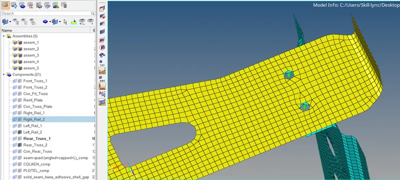
7. Right_Rail_1 & Right_Rail_2:- Spot-weld with Rigid Elements
3D > Connectors > Spot > Rigid

- Nodes are connected to the components and is as connected below,
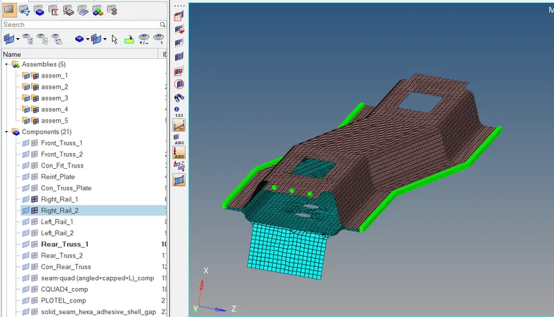
8. Left_Rail_1 & Left_Rail_2:- Spot-weld with Spring Elements
3D > Connectors > Area > Spring
- Connected the parts as shown below
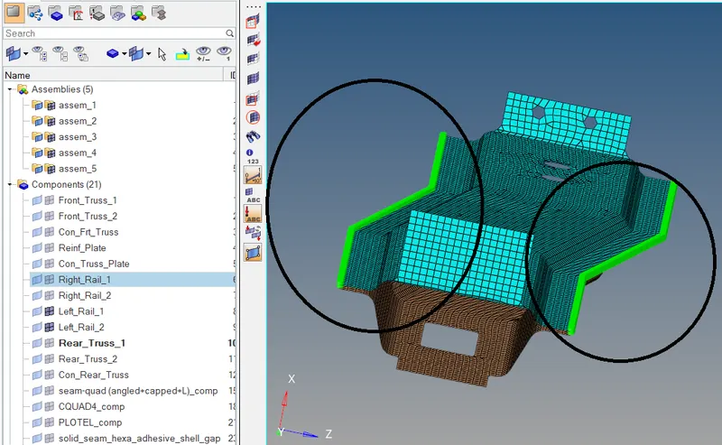
9. Rest all the component left Join them with suitable connectors
- Joined the unfixed parts using connectors.
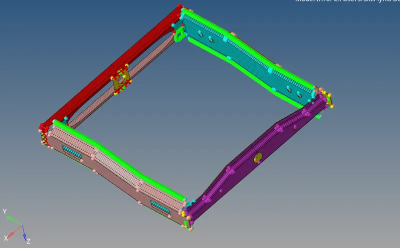
Result :
The components are connected using suitable connectors.and the model is attached below