Week 9-Creation of 1D Connectors Challenge
CREATION OF 1D CONNECTORS CHALLENGE:
OBJECTIVE:
Creating the various connectors from 1D, 2D, or 3D as suitable connectors such as spot, bold, seam, and area respectively and attach the various parts with these connectors.
PROCEDURE:
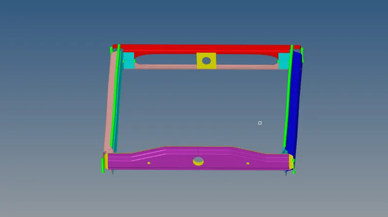
The model frame assembly has 9 parts such as front truss 1, front truss 2, right plate, right rail 1, right rail 2, left rail 1, left rail 2, rear truss 1, rear truss 2, and they have attached with different types of connectors to different parts respectively as mentioned below in the table.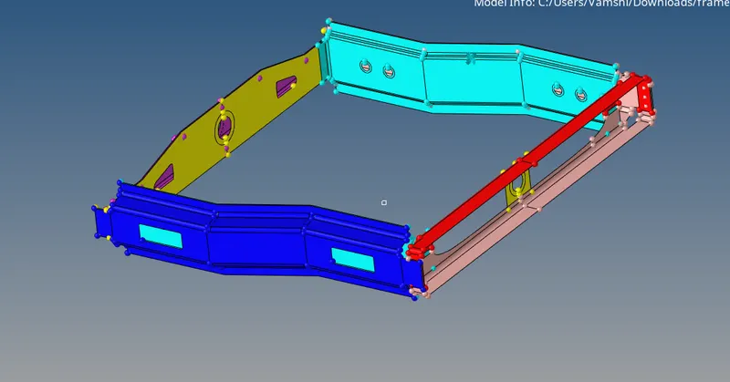
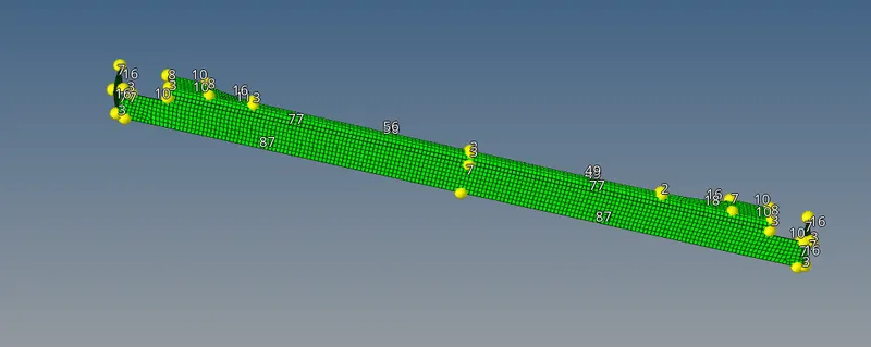
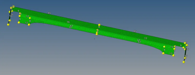
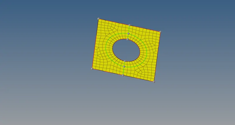
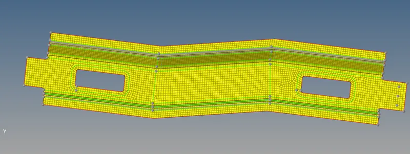
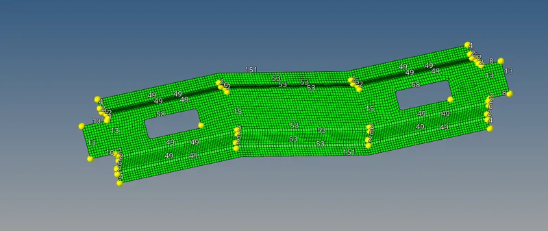
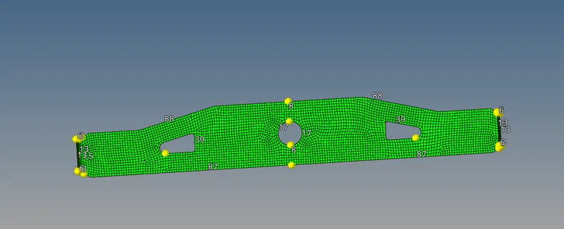
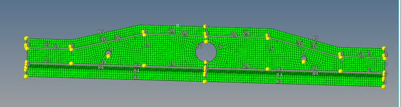
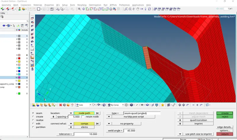
1) Right Rail 2 & Front truss 1:- Seam-Quad(angled+capped+L)
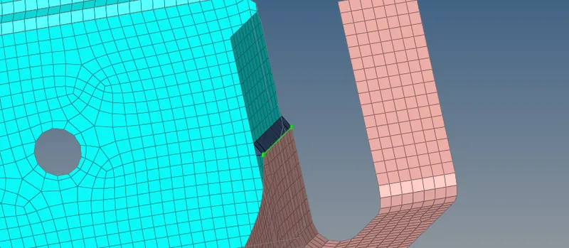
To create the above-shown connection I will go connectors under the 1 D menu and then go to seam and will select the nodes and specify the type as Seam-Quad(angled+capped+L) and also give the tolerance of 10 (as per the distance between two components) and spacing as 5 because it should be same as target element size, finally I will select the components in which I have to create the connection. The Seam-Quad(angled+capped+L) connection is shown below:
2) Left Rail_2 & Front truss 1:- Quad elements
use pitch size to imprint
To create the above-shown connection I will go to connectors under the 1 D menu and then go to seam and will select the nodes and specify the type as Seam-Quad and also give the tolerance of 10 (as per the distance between two components) and spacing as 5 because it should be same as target element size, finally I will select the components in which I have to create the connection. The seam quad connection is shown below:
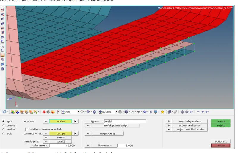
3) Front truss 2, Front_truss 1 & Right Rail 1:- Spot weld with 2 Layers and 5 mm Diameter
To create the above-shown connection I will go to connectors under the 1 D menu and then go to spot and will select the nodes and specify the type as weld and also give the tolerance of 10 (as per the distance between two components) and give the diameter as 5 because it should be same as target element size, and specify the layer as 2 then finally I will select the components in which I have to create the connection. The spot weld connection is shown below:
4) Front truss 2. Front truss 18 Left Rail 1:- Hexa (Adhesive)
To create the above-shown connection I will go to connectors under the 1 D menu and then go to seamn and will select the nodes and specify the type as Hexa(Adhesive) and also give the tolerance of 10 (as per the distance between two components) and spacing as 5 because it should be same as target element size, finally I will select the components in which I have to create the connection. The Hexa(Adhesive) connection is shown below:
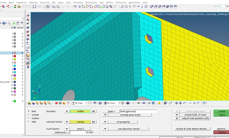
5) Rear truss 2 & Right Rail 2-Bolt Connector
To create the above-shown connection I will go to connectors under the 1D menu and then go to bolt and will select the nodes and specify the type as general and if there is no existing hole in the model click on the create hole, if none command. specify the tolerance as 10 (as per the distance between two components) finally, I will select the components in which I have to create the connection. The bolt connection is shown below:
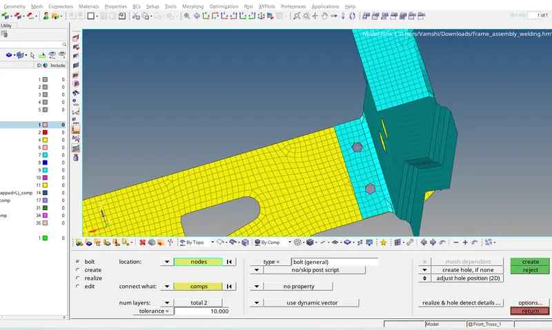
6) Rear truss 2 & Left Rail 2:- Bolt Connector
To create the above-shown connection I will go to connectors under the 1D menu and then go to bolt and will select the nodes and specify the type as general and if there is no existing hole in the model click on the create hole, if none command, specify the tolerance as 10 (as per the distance between two components) finally, I will select the components in which I have to create the connection. The bolt connection is shown below:
7) Right Rail 1& Right Rail 2:-Spot-weld with Rigid Elements
tolerance
To create the above-shown connection I will go to connectors under the 1D menu and then go to spot and will select the nodes and specify the type as rigid and also give the tolerance of 10 (as per the distance between two components) and give the diameter as 5 because it should be same as target element size, and specify the layer as 2 then finally I will select the components in which I have to create the connection. The connection should be mesh dependent and it should not affect the mesh. The connection is shown below:
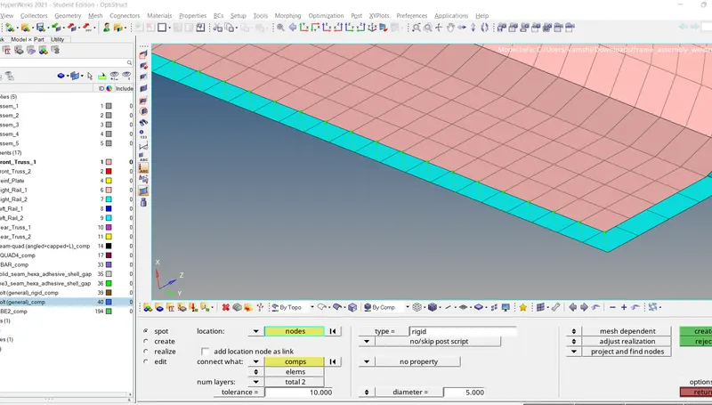
8) Left Rail 1& Left Rail 2:-Spot-weld with Spring Elements
To create the above-shown connection I will go to connectors under the 1D menu and then go to spot and will select the nodes and specify the type as spring and also give the tolerance of 10 (as per the distance between two components) and give the diameter as 5 because it should be same as target element size, and specify the layer as 2 then finally I will select the components in which I have to create the connection. The connection should be mesh dependent and it should not affect the mesh. The connection is shown below:
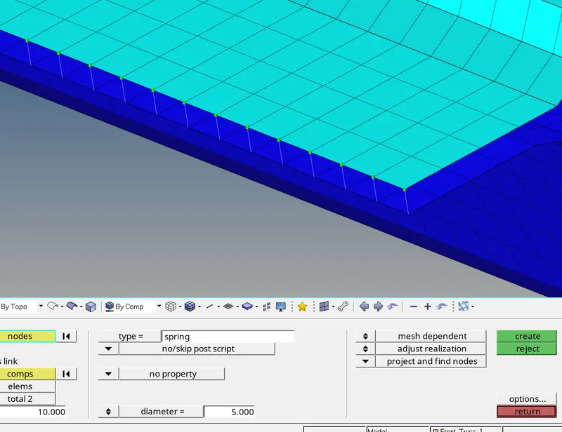
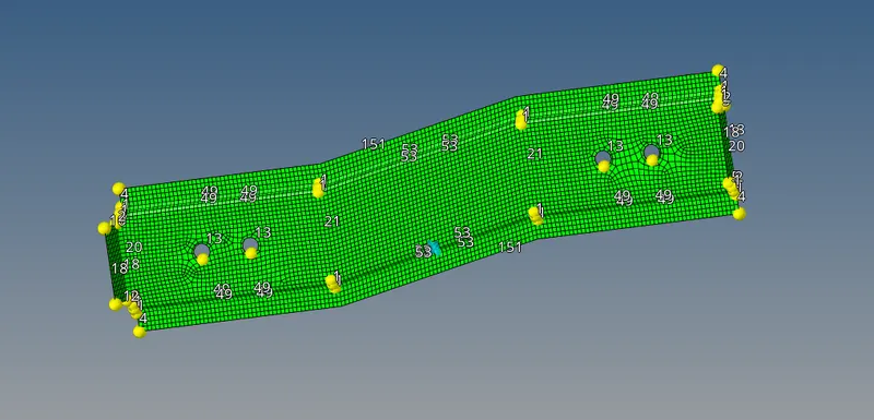
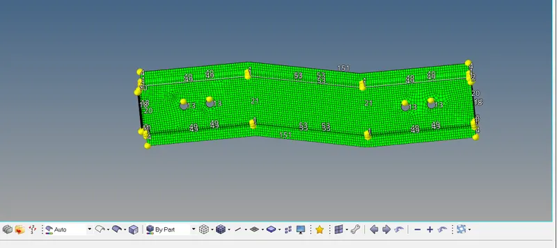
RESULT - All the components of the frame assembly model are attached and the final connections are shown below.