Week 9 - Creating connection for Rear door
AIM :
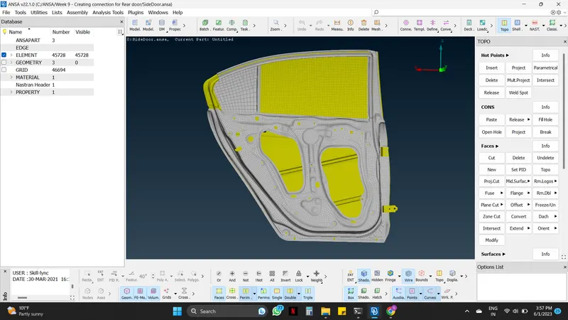
For the given Rear door FE model, Create and Apply different PIDs for different components and perform suitable connections for the FE model using ANSA.
OBJECTIVE :
- To give different types of connections for the rear door model of the car.
- These connections are given to the model using ANSA in the NASTRAN deck which will be used later for NVH simulation.
SOFTWARE TOOL USED :
ANSA Version 22.1.0
GIVEN DATA :
- CAD model.
THEORY :
1. Door Assembly :
Door assembly is a very important model in the car as it consists of different types of connection representations. Different mechanisms are also present in the door assembly model like door lock mechanism, hinge mechanism, glass slider mechanism, and latch mechanism.
Nowadays, automobiles are made using two strategies. One is using lighter materials for cost reduction and the other is by improving the design. A usually tailored cut is used while manufacturing the door model. In this tailored cut the door panel consists of two different thicknesses. The thickness to the side of the hinges is more than the thickness on the other side. This is because the whole weight of the door will act on the side which has more thickness. These two thicknesses are joined using laser welding. Laser welding is used as it has no filler material, ensuring that the original chemical composition is maintained due to the extreme focus of the beam, even the heat-affected zone is reduced to a minimum. It also consists of an atmospheric strip (usually made of rubber) which acts as a seal and does not allow outer air to flow inside the cabin.
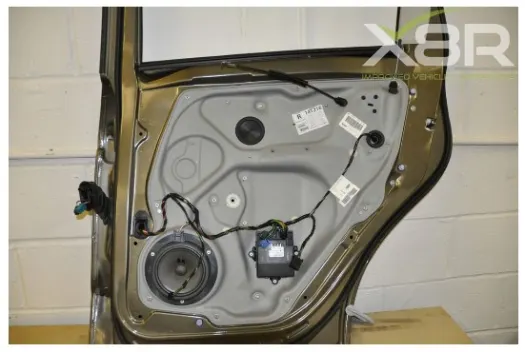
Fig. Dismantled door with panel
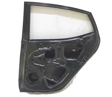
Fig. Dismantled door without panel
2. Connectors :
Connectors are geometric entities (not FE) primarily used to create spot and seam welds but also used to create adhesives, bolts, and masses. They are simply a database of information defining specific requests for connections at specific locations, a medium to create both solver independent and/or solver-dependent connections between geometric and/or FE entities. Connectors can be created interactively or from different master connection files (.xml, .mcf, .vip).
There are some types of Connectors, they are explained below :
i. Spot
Connections at a point
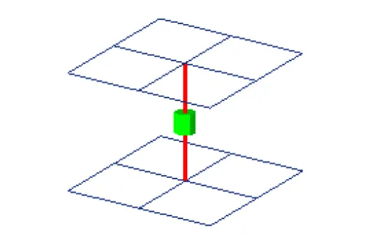
ii. Bolt
Connections at hole locations
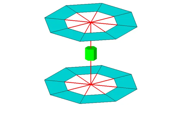
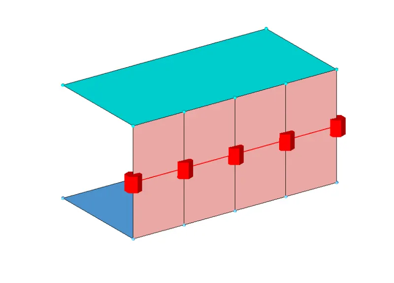
iii. Seam
- Connections along a length
- Seam welds
- Connects geometry only
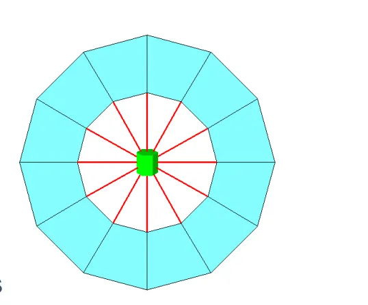
iv. Trim Mass
Simplification through replacement of parts with mass only or adding mass to existing parts. It is a Non-physical mass.
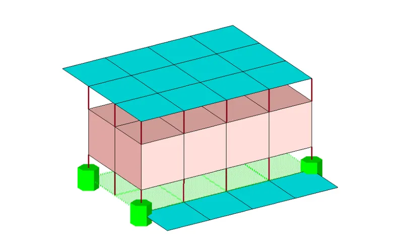
v. Area
- Connection of areas
- Adhesives
2. Connectors Terminology :
a. Link Entities - The entities that are being connected.
- Users can explicitly define link entities or specify a search tolerance.
- Can be components, elements, surfaces, nodes, or tags.
- Typically components are linked.
b. Connector Location - Where the entities are linked.
- Nodes – created at the node location.
- Points – created at the point location.
- Lines – created for the line may be split into multiple projection locations as specified by the offset, spacing, and density values.
- Elements – created at the element location (adhesives only).
- Surface – created at the surface location (adhesives only).
c. Connector Realization - The creation of the finite element representation of that connector.
- Rigids, springs, etc., or custom configurations such as ACMs, CWELDS, etc.
3. Three Types of Connector's State :
i. Unrealized - The initial status of the connector entity upon creation.
- Newly created or imported connector before the first realization.
- Editing the connector definition (i.e. add or delete a link entity from the connector), the connector removes the welds it created, and reverts back to an unrealized state.
ii. Realized - The status only if the creation of the FE weld representation at the connector was successful.
iii. Failed – The status of creating the FE weld representation at the connector was not successful (Failed).
- If the creation of the FE representation is unsuccessful (due to low tolerance, insufficient link entities, etc.) the connector icon is displayed as failed (red).
4. Types of Connections :
These are the Connection that is used mostly in industries-
- Seam Weld
- Spot Weld and
- Bolt Weld
i. Seam Welding and its Application
- Seam welding is the joining of workpieces made of similar or dissimilar materials along a continuous seam. Seam welding can be broken down into two main techniques, resistance seam welding, and friction seam welding.
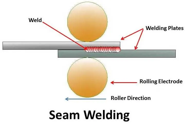
- It is used for welding stainless steels, steels alloys, nickel and its alloys, magnesium alloys, etc
ii. Spot Welding and its Application
- Spot welding (or resistance spot welding) is a type of electric resistance welding used to weld various sheet metal products, through a process in which contacting metal surface points are joined by the heat obtained from resistance to electric current.
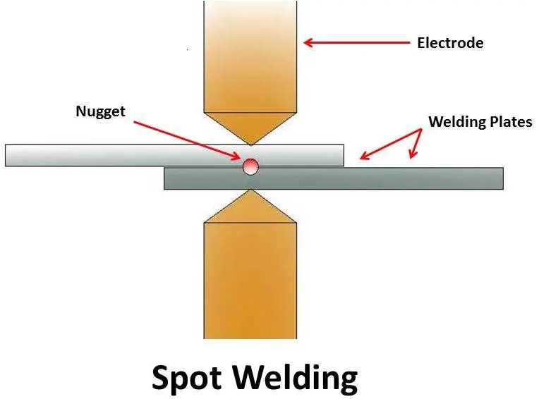
- Spot welding is typically used when welding particular types of sheet metal, welded wire mesh, or wire mesh.
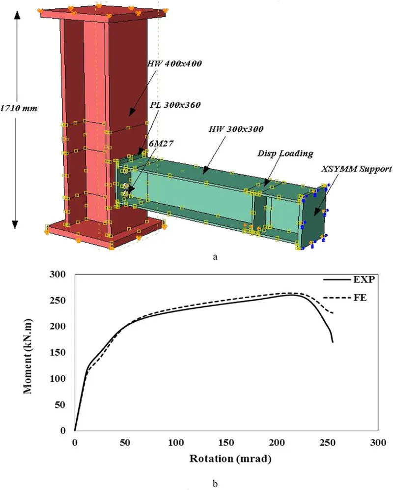
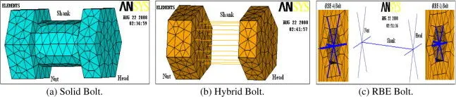
iii. Bolt Connection's Model
PROCEDURE :
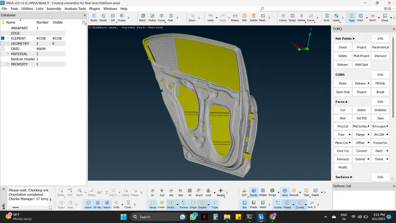
Step 01 : Importing CAD Model.
- The initial step is to import the geometry into ANSA Software.
File -----> Open -----> Select the file -----> Open (Or we can drag and drop the file into ANSA)
- There are file formats like IGES, STEP, and Parasolid where we can import these file formats into any CAD, or CAE Software.
- In ANSA we can import all the CAD Software file formats like
i. IGES [Initial Graphics Exchange Specification].
ii. STEP [Standard for the Exchange of Product Model Data].
iii. Solidworks
iv. Catia V5, V6
v. Simens NX CAD
vi. Inventor
vii. Creo
viii. Solid Edge
ix. Rhinoceros 3D
- IGES and STEP, These two are standard file formats that are mostly used in industries. But nowadays in industries, they are also using the Parasolid file format.
Step 02 : Geometry cleanup
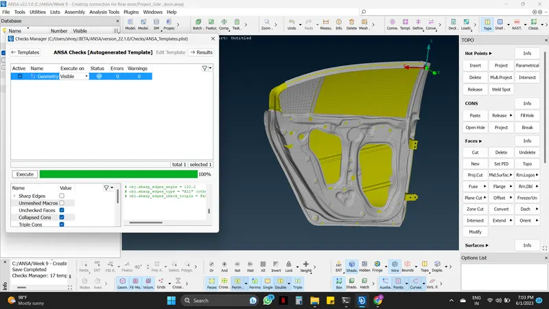
- The cleanup will be checking any geometrical errors and cleaning it.
Tool tab -----> Check -----> Geometry -----> Execute -----> If any errors pop up in red color select them at once -----> Right mouse click -----> Fix -----> If not fixed, try manually -----> Then execute the geometry check again, it will show No errors or warning exist.
Step 02 : Creating Property ID
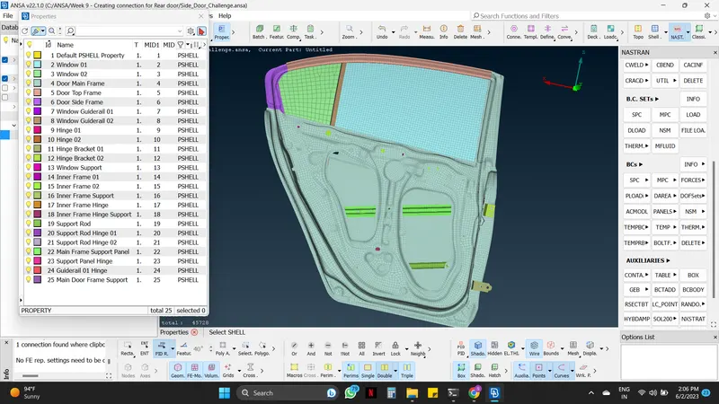
- For every Component of the Rear door, a separate property ID (PID) must be assigned.
- For assigning PID, the Set PID command is used.
Topo module -----> Faces -----> Set PID -----> Macros/Shells -----> Using the boolean operations select the component which is to be assigned and mouse middle click -----> Dialogue box will appear, create new Pshell -----> OK
Step 02 : Creating the Connections.
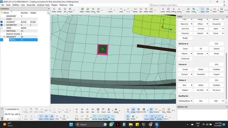
Deploying Bolt Connectors in Hinges :
Following are the steps to Deploying the Bolt Connection
i) Create a point in the circular edges
Topo module -----> Points -----> On COG -----> Select the Hole where the point must be created -----> Mouse middle click.
ii) Convert the point into Bolt
Assembly Tab -----> Convert -----> 3D Points, select the point which was created and mouse middle click -----> Select Bolt -----> OK.
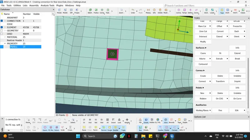
iii) Deploying the Connection
Assembly Tab -----> Connection Manager -----> Select the Bolt and mouse middle click -----> Dialogue box will appear -----> Right click on P1, in modify column click F1, select appropriate part -----> Repeat Previous step according to the surface and change P1 with P2, P3... -----> Apply and Realize.
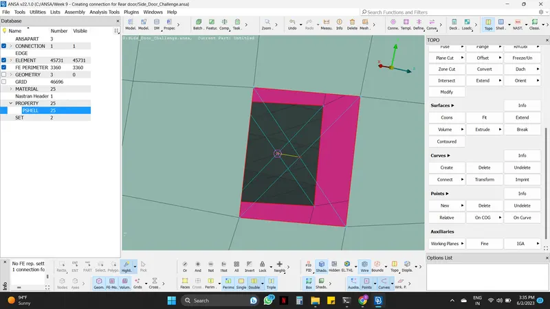
- Here while deploying the connection Select the zones option in the FE rep. Settings as In/Out or Inner.
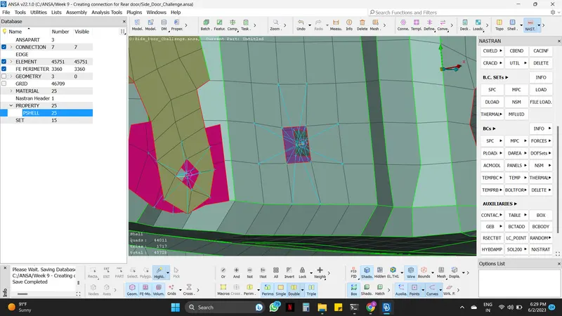
Fig. Zones : In/Out
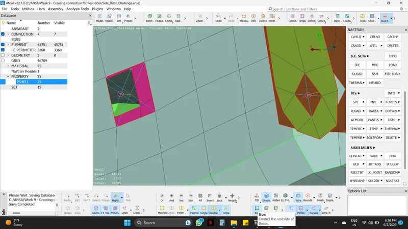
Fig. Zones : Inner
- Similarly do the same process in every region where the bolt connection is required.
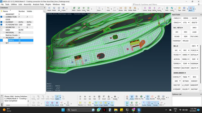
Creating RBE2 Elements in Required Regions :
- The RBAR or RBE2 element can be used for connecting two nodes to model a 'rigid' welded type connection, with all 6 DOFs, or a pinned connection with 3 translational DOFs. The RBE2 element can also be used to model a wagon wheel-type connection between the independent and the dependent nodes.
Following are the steps to Deploying the RBE2 Elements
Nastran Deck Module -----> Elements -----> RBE2 -----> Many nodes -----> Select the Slave nodes -----> Mouse middle click and finish -----> In the model browser create a new part -----> Name it and store every connection of RBE2 in it.
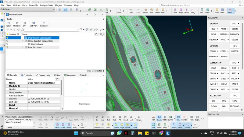
- Here all the Nods on the main Frame were connected with the RBE2 method.
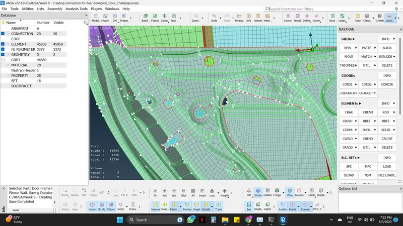
Creating Cluster RBE2 Elements :
- The RBE2 method and the Cluster RBE2 method are almost similar in performance, only the obtained result is different.
- In the RBE2 method, only 1 hollow section is selected with 1 single-parent node which ANSA detects automatically between the hollow section. But in the Cluster RBE2 method, two Hollow section is selected and ANSA detects one single parent node between them.
Following are the steps to Deploying the Cluster RBE2 Elements
Nastran Deck Module -----> Elements -----> RBE2 -----> Many nodes -----> Select the Slave nodes of both the hollow section at once -----> Mouse middle click and finish -----> In the model browser create a new part -----> Name it and store every connection of RBE2 in it.
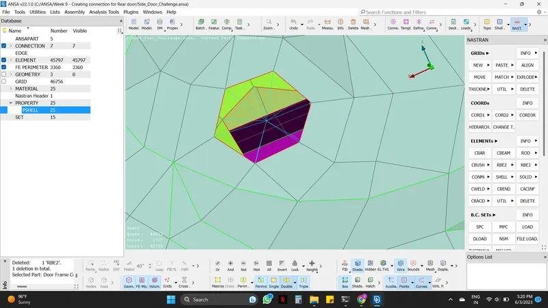
Creating a Spot Weld Connection :
- In the Fig below the Hinges must be connected to the Support Rod, Hence a Spot weld connection must be applied.
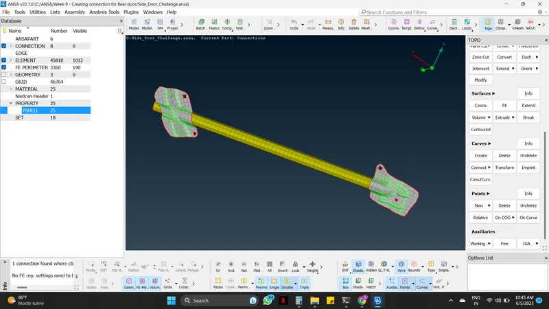
For creating a Spot weld Connection following steps must be followed,
i) Create a 3D point in the area where the weld must be done.
Topo module -----> Points -----> On COG -----> Select the area where the point must be created -----> Mouse middle click.
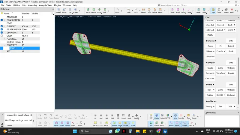
ii) Convert the 3D points into spot weld.
Assembly Tab -----> Convert -----> 3D Points, select the point which was created and mouse middle click -----> Select spot weld -----> OK.
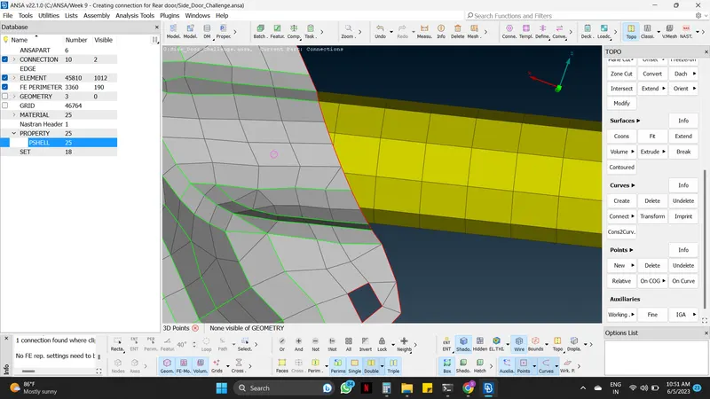
iii) Deploying the Connection
Assembly Tab -----> Connection Manager -----> Select the spot weld and mouse middle click -----> Dialogue box will appear -----> Right click on P1, in modify column click F1, select appropriate part -----> Repeat Previous step according to the surface and change P1 with P2, P3... -----> Select RBE3-HEXA-RBE3 in FE. Rep Type, 20 in search distance, and create PSOLID -----> Apply and Realize.
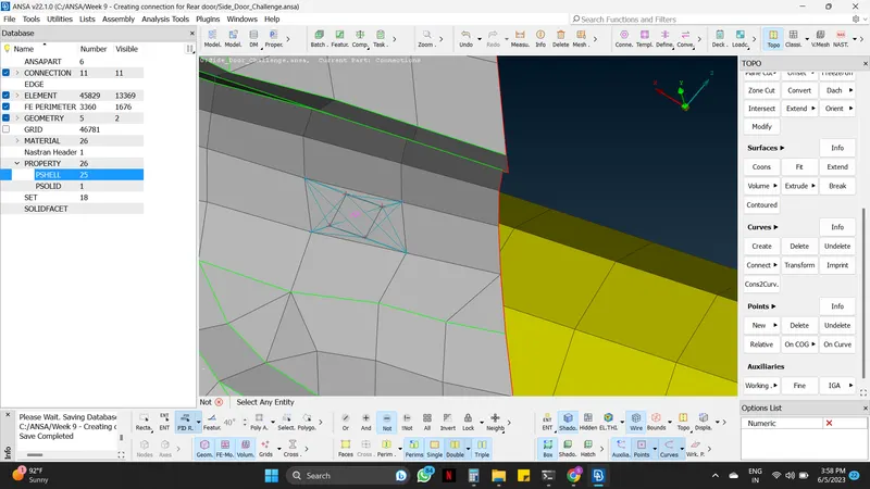
For every spot weld the above step must be done separately.
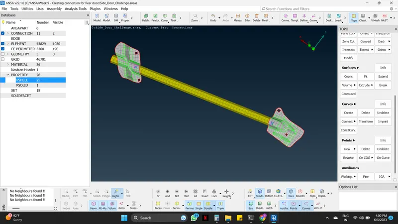
Creating a Seam Weld Connection :
- In the Fig below the Hinge must be connected to the Door Main Frame, Hence a Seam weld connection must be applied.
- The weld data is not available, hence assumption must be done. For that use the Cons2curve command in the Topo module and create a curve with respect to the hinge.
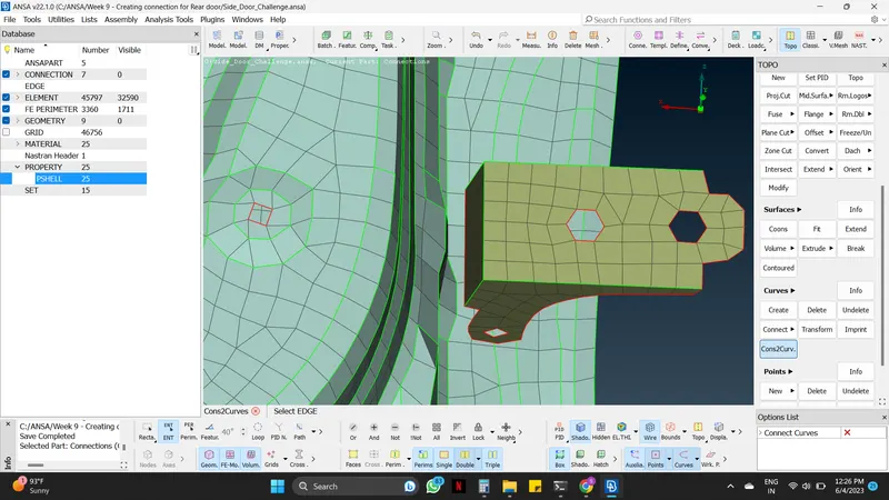
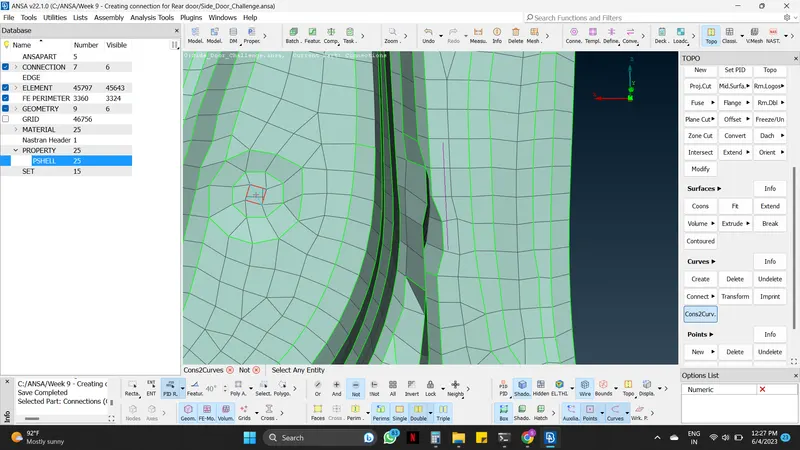
- Now this curve must be converted into the connection data, for that use the convert option on the Assembly tab and convert the curve into the seam line connection data.
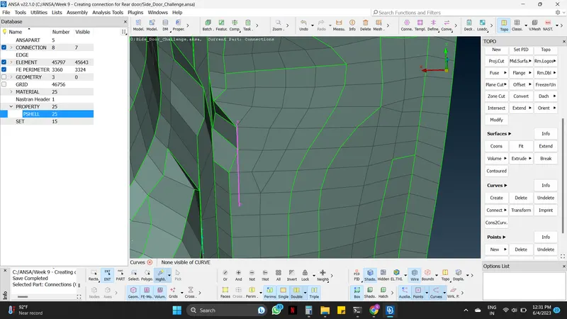
- For deploying the connection following steps must be followed,
Assembly Tab -----> Connection Manager -----> Select the Seam line connection data and mouse middle click -----> Connection manager Dialogue box will appear -----> Select Overlap shell in FE. Rep Type (as the surface is Parallel to each other Overlap shell is used) -----> Right-click on P1, in modify column click F1, and select the appropriate part -----> Repeat the Previous step according to the surface and change P1 with P2 -----> Apply and Realize.
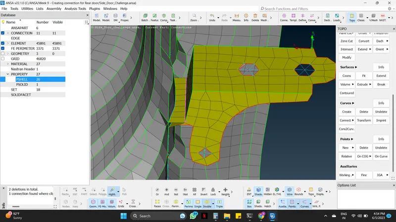
Creating Door Handle Connection :
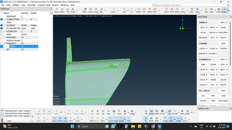
- In the above fig the Door handle hollow section is shown, For creating the connection following steps must be followed.
i) Creating the connection in those two hollow sections.
Nastran Deck Module -----> Elements -----> RBE2 -----> Many nodes -----> Select the Slave nodes of any one hollow section -----> Mouse middle click and finish -----> In the model browser create a new part -----> Name it and store every connection of RBE2 in it.
Similarly do the same steps for the other hollow section
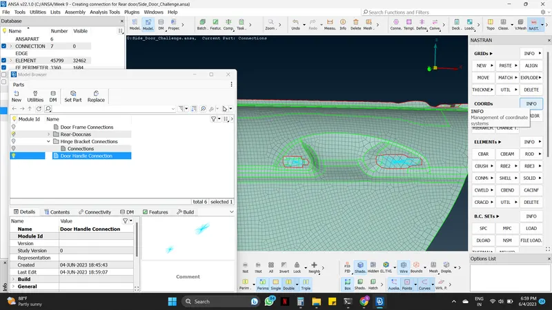
ii) Creating a connection for those two connections.
The steps will be similar to the above just select the parent nodes of the created connection as slave nodes.
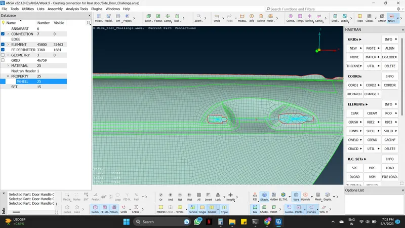
iii) Assigning Mass to the master node.
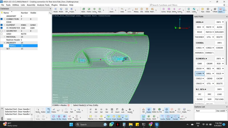
- As this is the connection of the door handle hollow section, in the future, there will be a door handle with some mass. Hence here the mass must be assigned.
- For assigning the Mass following steps must be followed
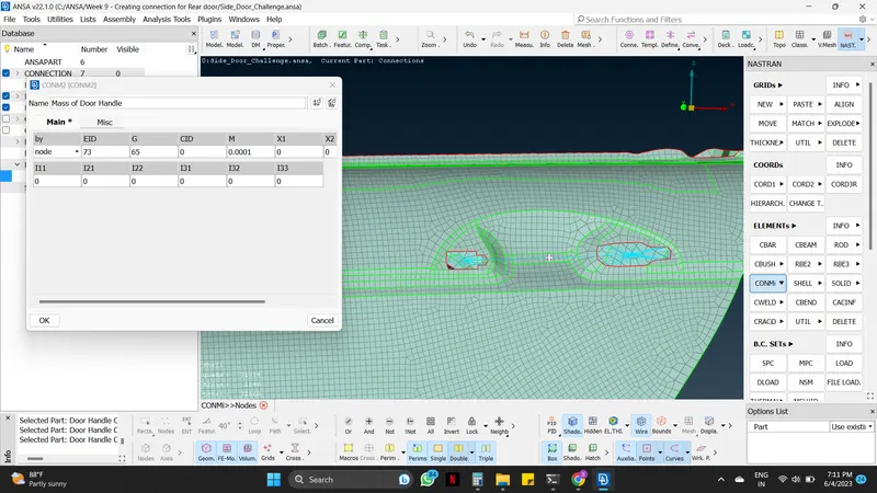
Nastran Deck Module -----> Elements -----> CONMi -----> CONM2 -----> Nodes and Select the center node -----> Mouse middle click and a dialogue box will appear for mass values -----> Enter the Mass Value as 0.0001 below the M column -----> Mouse middle click.
NOTE :
- The Mass Value is taken randomly as 100 grams.
- The mass value must be given in tons (1 Tonne = 1000000 Grams)
- Hence mass value will be 0.0001
Creating Connections for the Windows :
- There is some mechanism for opening and closing the Windows but while simulation it must be considered as a rigid connection. The windows must be connected with either the Door frame or the Weather strips.
For creating the connection following steps must be followed
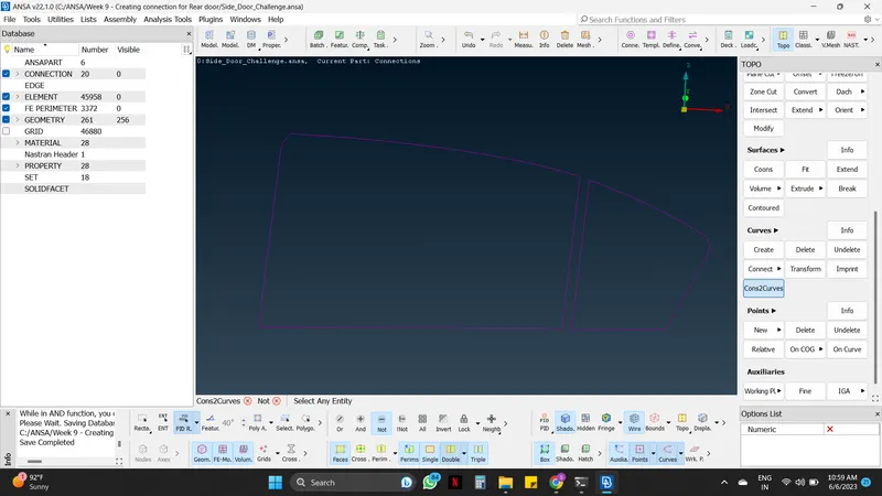
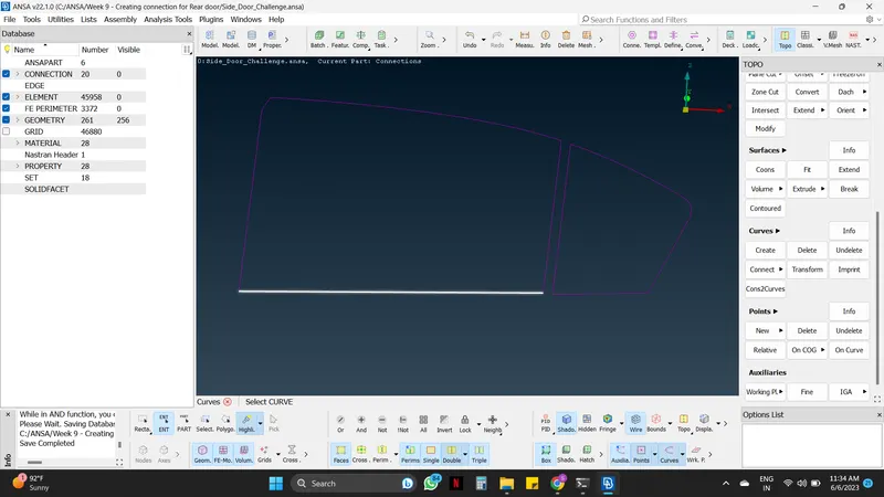
i) Making Curves around the Glass.
Topo Module -----> Curves -----> Cons2Curves -----> Select the Boundary of the Glass -----> Mouse middle click.
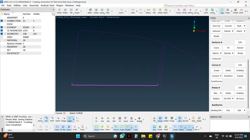
ii) Creating one more Curve at the bottom.
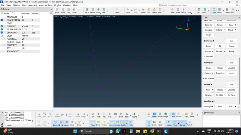
- In the bottom area the mechanism is present and through that mechanism the window glass will slide up and down.
- For that movement the glass must be connected on the both side of thr Door frame, Hence two curves.
Utilities Tab -----> Transform -----> Copy -----> Select the bottom entities -----> Enter 1 in dy column as the copy must be done in the Y direction -----> Mouse middle click -----> Finish.
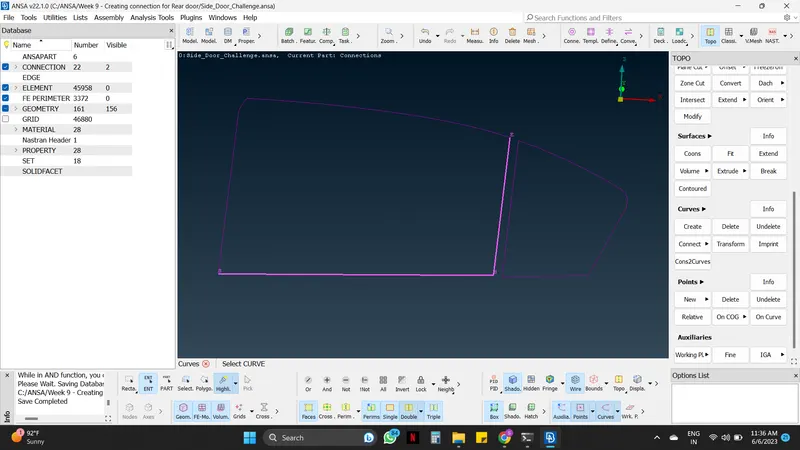
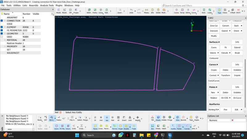
iii) Converting the Curves into Seam Line.
Assembly Tab -----> Convert -----> Curves, Select the curves in order (Bottom, left, right, top) which was created and mouse middle click -----> Select Seam Line -----> OK.

iii) Deploying the connection on each Seam Line.
Assembly Tab -----> Connection Manager -----> Select the Seam line connection data and mouse middle click -----> Connection manager Dialogue box will appear -----> Right-click on P1, in modify column click F1, and select the appropriate part -----> Repeat the Previous step according to the surface and change P1 with P2 -----> Select RBE3-CBUSH-RBE3 in FE. Rep Type, Search Dist - 50, Create PID and insert it in PBUSH -----> Apply and Realize.
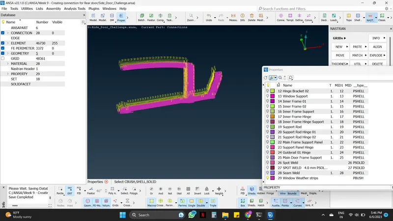
iv) Orientation of the CBUSH.
- While deploying the connection on the seam line, the connection are deployed in different direction.
- Hence for aligning all the connection in same direction orientation must be given.
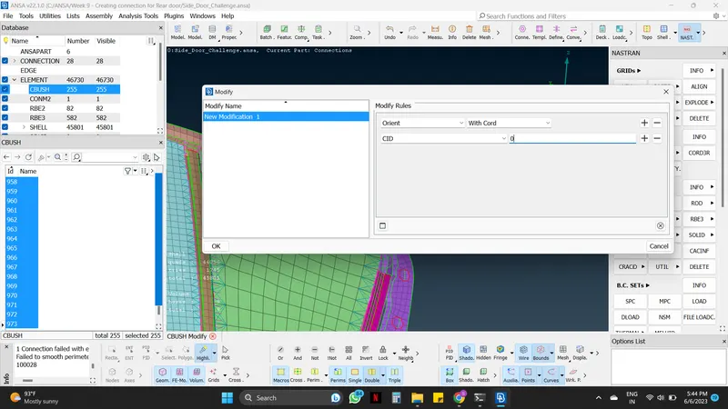
Database -----> Elements -----> Mouse left double click on CBUSH -----> Select all the CBUSH PID's and click on modify -----> In first column select orient and in front of that other column select with Cord -----> Left mouse click on + sign -----> First column select CID and in front of that other column enter value 0 -----> OK.
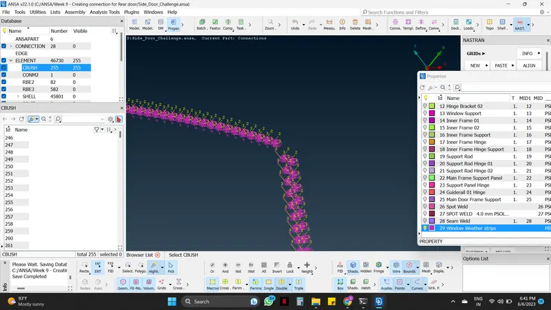
- Now all the Seam line connection is convert in one single direction.
LEARNING OUTCOMES :
By doing this Project, the following aspects can be learned:
- Perform geometry cleanup for any complex 3D model.
- Deploying the connection on different surfaces, hollow section, hinges, panels, glass, and etc.
- Familiarized and working with all the commands such as RBE2,RBE3-CBUSH-RBE3,RBE3-HEXA-RBE3 and CONMI2 element using the NASTRAN deck module.
- Work on ANSA with a flow.
CONCLUSION :
- For performing any kind of simulation the connection of the automobile parts must be done properly.
- The connection must be done accordingly to the part as there are some consideration must be done like type of connection, method to connection, assumption, given values and criteria, presentation, and effectiveness.
- After all this consideration connection must be deployed with proper commands, this will make the Automobile parts ready for further simulation or any other process.