Connectors in HyperMesh
OBJECTIVE:
To create connectors at the different joints and attach the various parts in the given model. The connectors to be used at the different joints are as given below:
- Right Rail 2 & Front truss 1: Seam-Quad(angled+capped+L)
- Left Rail 2 & Front truss 1: Quad elements
- Front truss 2, Front truss 1 & Right Rail 1: Spot weld with 3 Layers and 5 mm Diameter
- Front truss 2, Front truss 1 & Left Rail 1: Hexa (Adhesive)
- Rear truss 2 & Right Rail 2: Bolt Connector
- Rear truss 2 & Left Rail 2: Bolt Connector
- Right Rail 1 & Right Rail 2: Spot-weld with Rigid Elements
- Left Rail 1 & Left Rail 2: Spot-weld with Spring Elements
- Rest all the component left Join them with suitable connectors
SOLUTION:
Connectors are elements which are used to represent connections between other geometrical entities. HyperMesh offers different types of connectors in 1D, 2D and 3D for this purpose. It includes weld, adhesives, bolts, area contact and so on. The first step to create connectors in hypermesh is to create the meshed model of the body. The connectors created are referenced to the nodes and elements present in this mesh model. It’s important to note that creation of some connectors distort the mesh on the parent model. Hence after generating the connectors, the mesh needs to be modified for good mesh flow and satisfying all quality criterions.
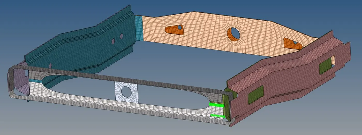
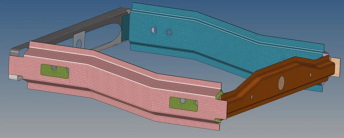
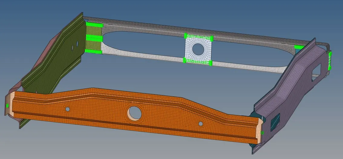
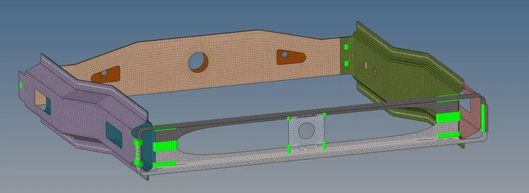
The given model named frame assembly has 9 different parts and the objective of this project is to create appropriate connections between each of these parts.
Step 1:
The first step is to create a 2D mesh on the model with good mesh flow and satisfying all quality criterions. The element size was taken as 5mm and the mesh was made using quad elements with minimum tria elements.
Step 2:
In the next step we create connectors between the each adjacent parts.
- Right Rail 2 & Front Truss 1: Seam Quad (angled + capped + L)
The seam weld connector is created at the free ends of the parts. For seam quad connectors, go to 2D → connectors → seam → location: nodelist → select the nodes along which the weld is to be created → type: seam-quad (angled + capped + L) → spacing: 5mm → select components which are to be joined → input required cap angle (here 65 deg) → tolerance: 10 → create
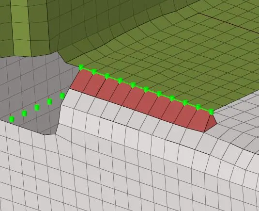
Following the above procedure creates the seam quad weld. It is possible that sometimes the connector may not be realized. In such cases, check for tolerance values. The tolerance value should be large enough so that the gap between the parts is taken into consideration. Further, it is common for the connector to not realize because it was created in the opposite direction. In this case the connector may be realized by reversing the direction of the feature.
2. Left Rail 2 & Front truss 1: Quad elements
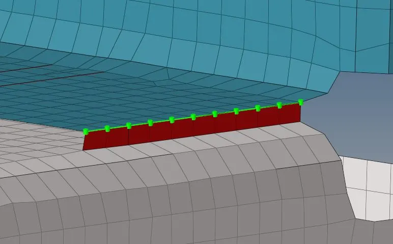
For quad connectors, go to 2D → connectors → seam → location: nodelist → select the nodes along which the weld is to be created → type: quad → spacing: 5mm → select components which are to be joined → tolerance: 10 → create
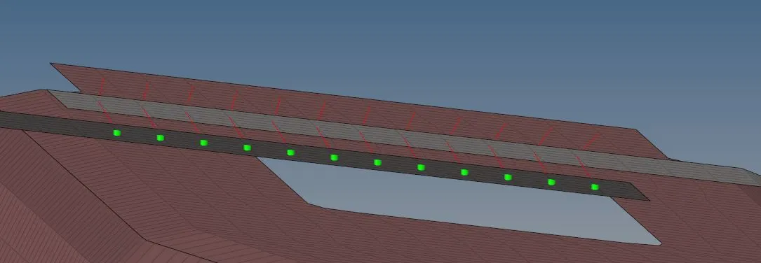
3. Front truss 2, Front truss 1 & Right Rail 1: Spot weld with 3 Layers and 5 mm Diameter
For spot weld connectors, go to 2D → connectors → spot → location: nodelist → select the nodes along which the weld is to be created → type: weld → diameter: 5mm → select components which are to be joined → tolerance: 10 → create
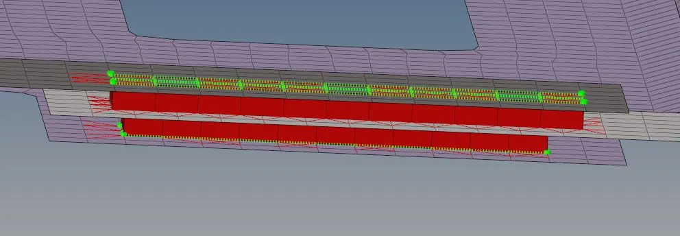
4. Front truss 2, Front truss 1 & Left Rail 1: Hexa (Adhesive)
For adhesive connectors, go to 2D → connectors → area → location: elements → select the elements along which the adhesive is to be created → type: adhesive → select components which are to be joined → tolerance: 10 → create
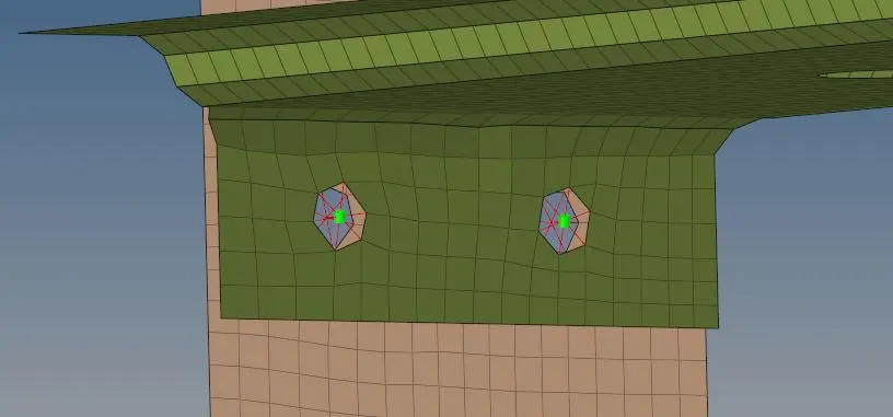
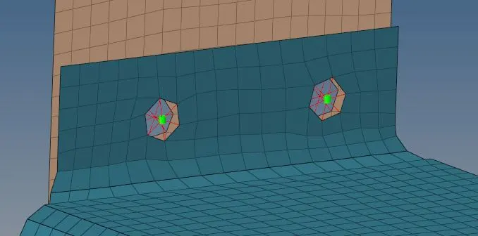
5. Rear truss 2 & Right Rail 2: Bolt Connector AND Rear truss 2 & Left Rail 2: Bolt Connector
For bolt connectors, go to 2D → connectors → bolt → location: nodes → select the node along which the bolt is to be created → type: CBAR → select components which are to be joined → tolerance: 10 → create hole, if none → create
6. Right Rail 1 & Right Rail 2: Spot-weldwith Rigid Elements AND Left Rail 1 & Left Rail 2: Spot-weld with Spring Elements
For spot weld connectors, go to 1D → spotweld → using nodes → select the nodes along which the weld is to be created → type: rigid or spring → create
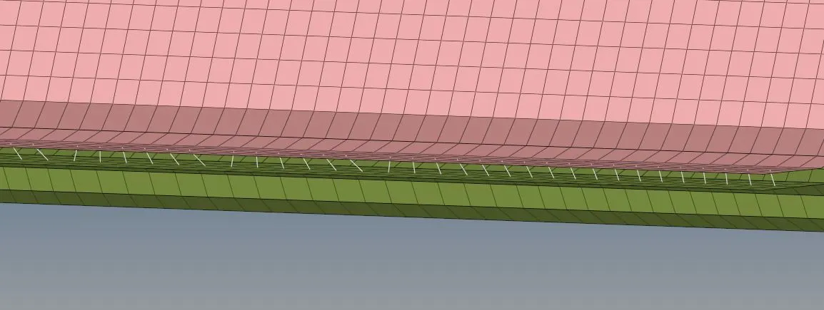
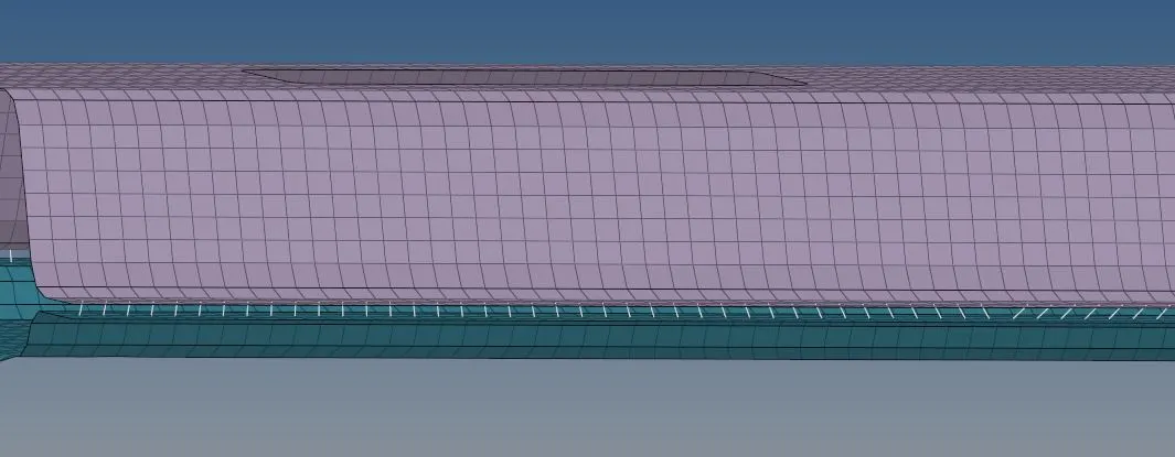
7. Rest of the components were joined using appropriate connectors
The final model with all the connections is shown below:
CONCLUSIONS:
1. The given parts were meshed prior to creating the connectors.
2. Connectors as mentioned in the problem definition were generated between the parts.
3. The mesh distortions due to creation of connectors were modified to get good mesh flow and quality.