Week 9 Challenge
Aim:
1)In a river of linear waterway 90 m and design discharge as 700 cumec and having silt factor as 1 . Fix the span and type of foundation
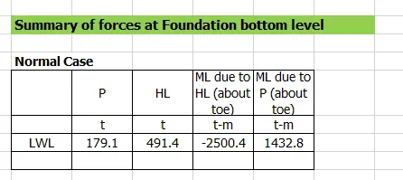
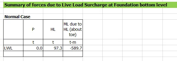
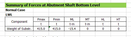
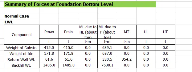
Calculate the forces as per IRC 6 on the foundation and propose the foundation.
- assume simply supported bridges
- continuous bridge.
2) What is zero shear point and if there is more scour at region what will be the effect of that on zero shear point.
3) Define the Liquefaction and its effects, how it can affect foundation. Also list the remedial measures for the same. How it is different from scouring?
Introduction :
Given - Linear waterway = 90m
Design discharge = 700 cumec
Silt factor = 1
HFL = 3m aove GL
Velocity = 1.2m/s
Road Level = 100m
GL = 93.5m
Pile dia = 1.2m Vertical capacity pile = 250 ton Horizontal capacity pile = 35 ton
Well dia = 8m Capacity = 70 tonnes/m2
Well dia = 6m Capacity = 50 tonnes/m2
Well dia = 7m Capacity = 60 tonnes/m2
Procedure :
1)In a river of linear waterway 90 m and design discharge as 700 cumec and having silt factor as 1 . Fix the span and type of foundation
Calculate the forces as per IRC 6 on the foundation and propose the foundation.
- assume simply supported bridges
- continuous bridge.
Ans. Scour depth dsm = 1.34(Db^2/ksf)^(1/3)
Db = Design discharge = 700cumecs
ksf = silt factor = 1
As per IRC SP 13 The value of Db shall be total design discharge divided by the effective linear waterway between abutments or guide bunds.
Regime surface width of the stream
W=4.8Q^(1/2) =4.8*(700)^1/2 = 127m > Linear water way (90m)
Db = 700/90 = 7.8m3/s per m width
Ksf = 1
dsm= 2.66 m
Max Scour depth for pier = 2xdsm = 5.32 m.
Max Scour depth for abutment with approach retained or lowest
bed level whichever is deeper = 1.27xdsm = 3.38m
Max Scour depth for abutment with scour all around = 2xdsm = 5.32m.
Max scour depth = 5.32m which is measured from HFL
HFL to GL is 3m, free standing length would be 2.32m or less, therefore we can go for pile foundation.
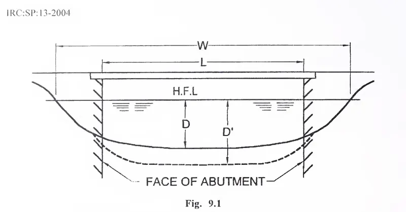
As per IRC SP 13 the total length of bridge shall be equal to linear waterway, so as to not obstruct the flow too much dividing the bridge into 2 portions, linear waterway = 90m therefore span = linear waterway/2 = 90/2 = 45m.
We can also take it upto width of regime but here we limit it to linear waterway.
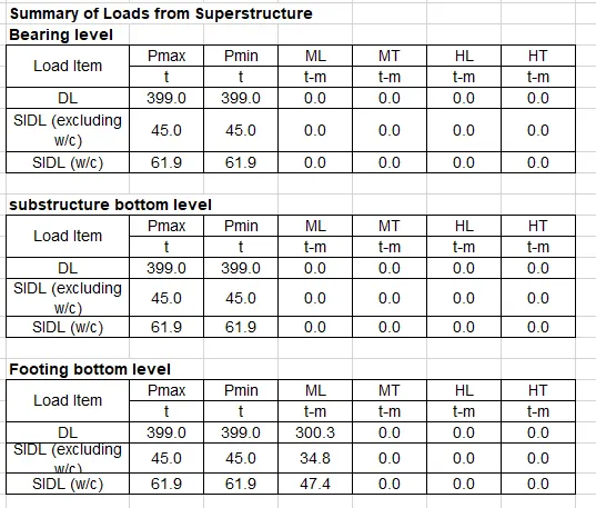
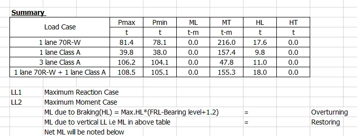
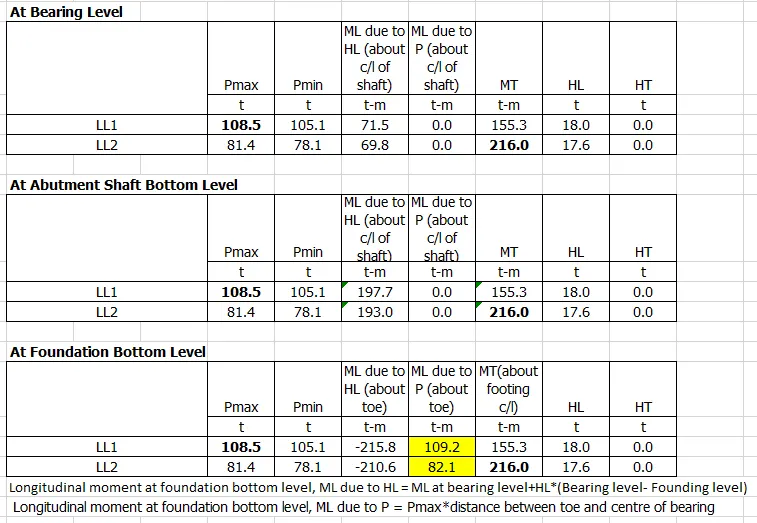
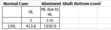
Force calculation as per IRC 6
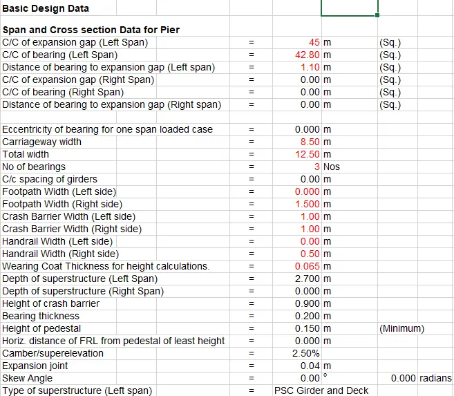
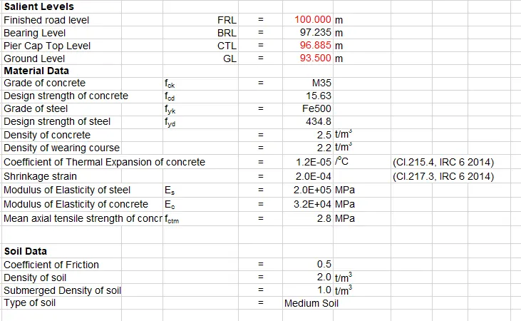
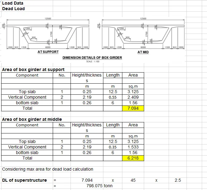
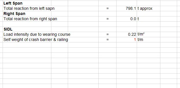
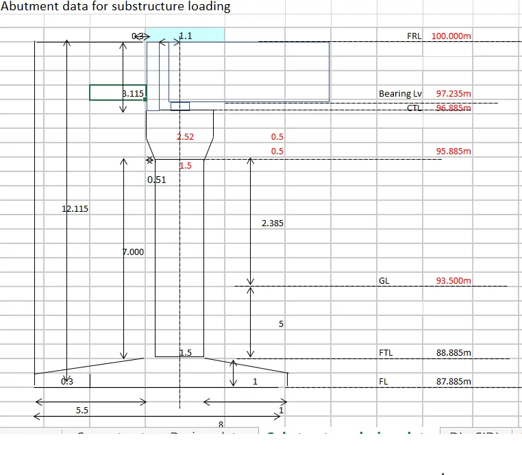
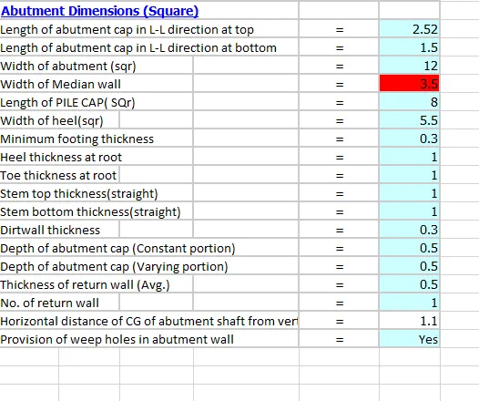
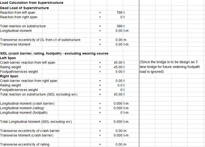
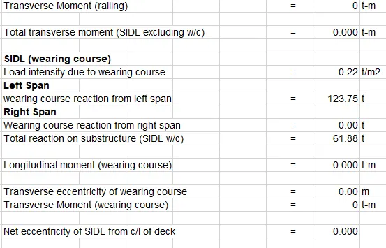
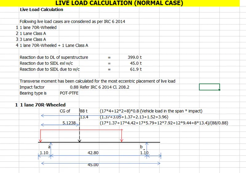
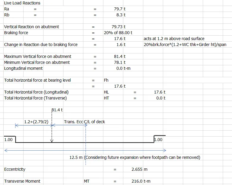
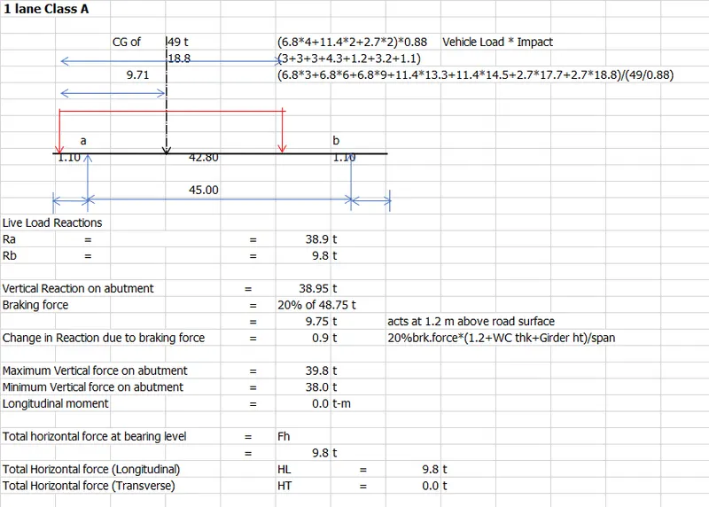
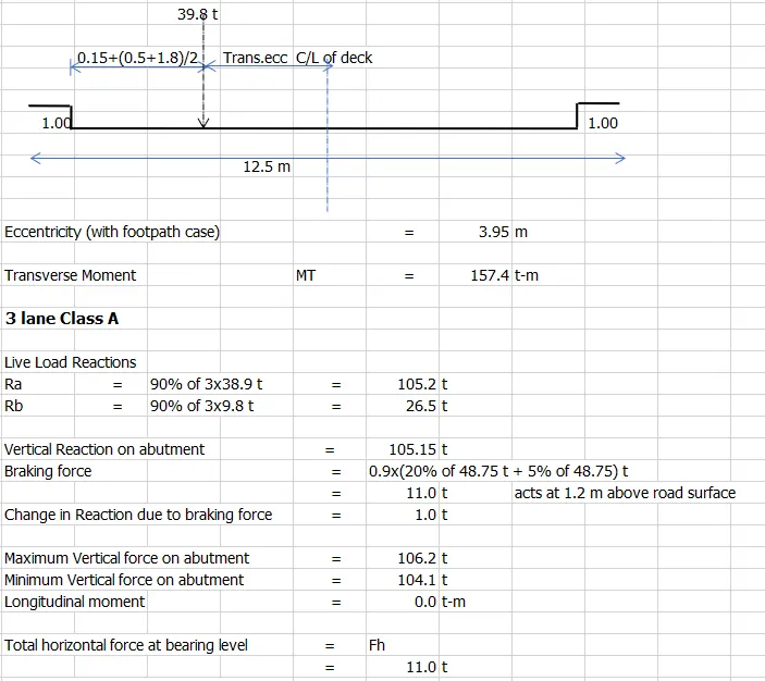
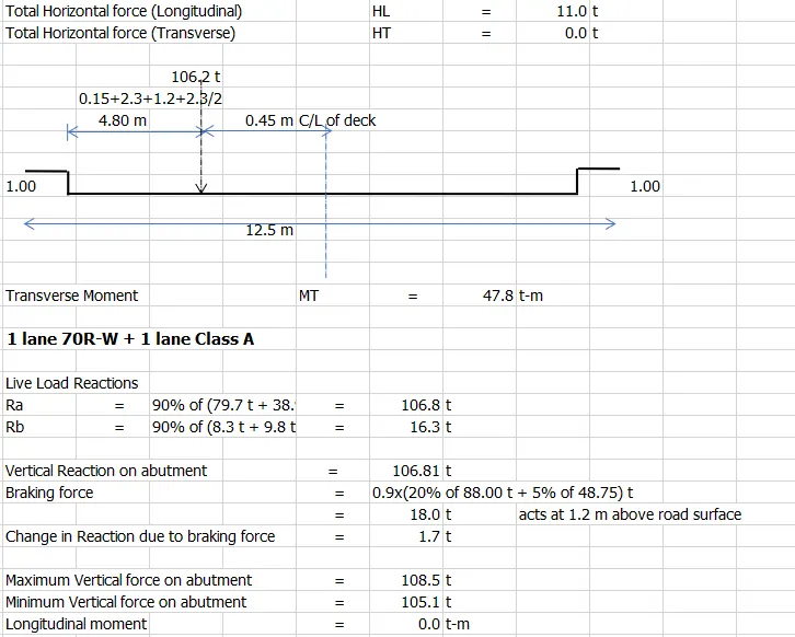
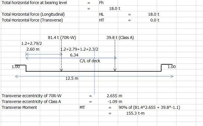
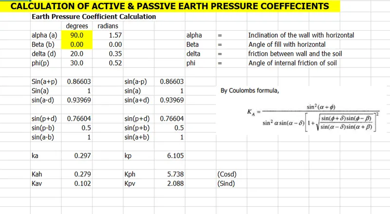
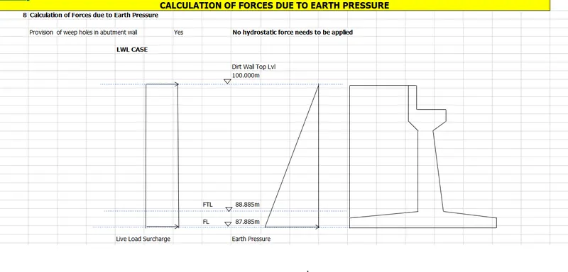
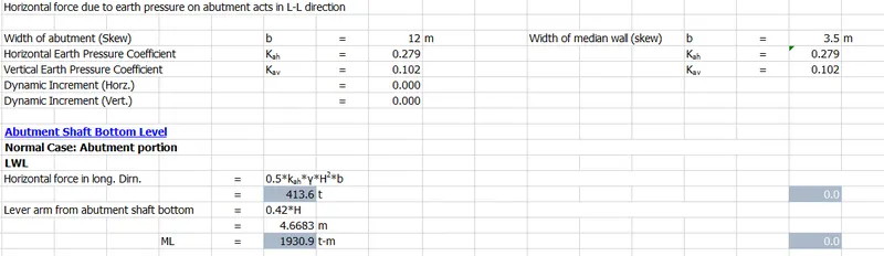

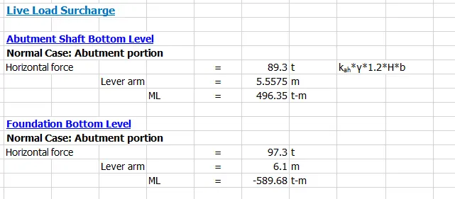

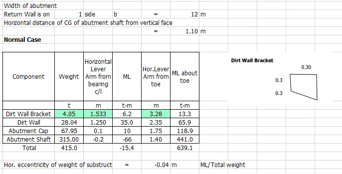
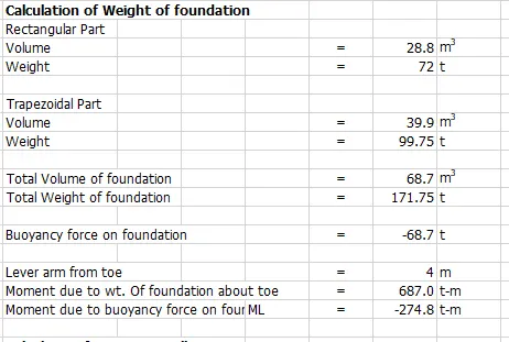
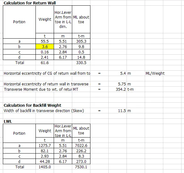
In case of simply supported span & continuous spans the calculation of horizonatl forces acting on bearing differs as per IRC 6 shown below:
1. Simply supported bridges
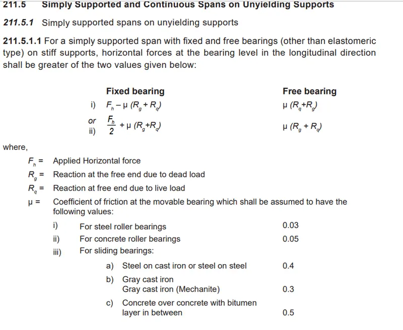
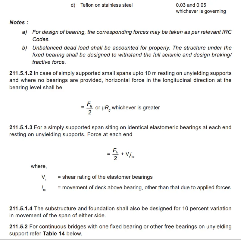
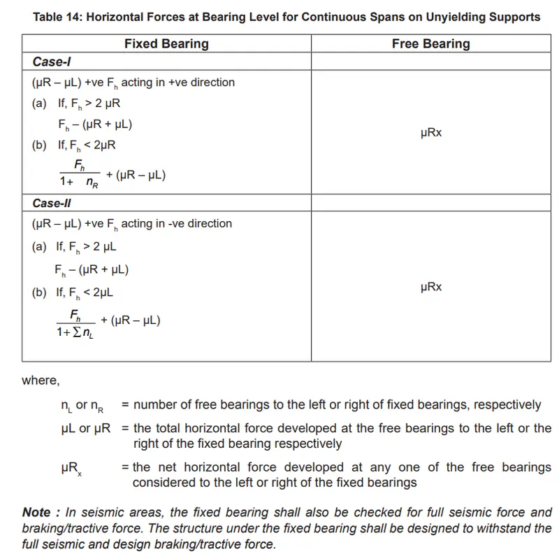
2) What is zero shear point and if there is more scour at region what will be the effect of that on zero shear point.
Ans. The point at which we get zero shear force we get the maximum bending moment of that section/beam at that point.
The bending moment is maximum at a point where the shear force is zero, because if the shear force was not zero at that point, that shear force value will cause a moment at a neighboring point according to its arm (distance) to that point. This will cause the moment to be larger at a neighboring point. But at a point where the shear force is zero the bending moment will not be larger in the neighboring areas since there is no shear force at that point to cause bending moment. This will make the point where the shear force is zero to be the maximum or minimum.
You can also think of the bending moment value as the area under the shear force curve up to that point. As long as the curve is not zero the moment will increase as you move along the length of the beam. When you hit a zero point or the shear force moves from positive to negative values, the moment will stop increasing and that point will be the maximum.
Also, it is said that it does not have to be zero at the maximum bending moment. That is true only if you have discontinuous in the bending moment diagram meaning that there is a couple (an applied moment at that point) that will cause a sudden change in the bending moment diagram. The other possible case is that there is a discontinuity in the shear force diagram due to concentrated forces. The example of the cantilever given in the answers is an example of that case. Mind that the value of the shear force at the support is both zero and the value of the reaction because it’s discontinues at that point.
if there is more scour at region the soil will keep on decreasing its shear strength, by the time a point comes where shear strength will become zero and soil will beacome liquified as during earthquakes which can lead to cracks in the structure or drastic damage to the structure.
3) Define the Liquefaction and its effects, how it can affect foundation. Also list the remedial measures for the same. How it is different from scouring?
Ans. Liquefaction is a phenomenon in which the strength and stiffness of a soil is reduced by earthquake shaking or other rapid loading. Liquefaction and related phenomena have been responsible for tremendous amounts of damage in historical earthquakes around the world.
Liquefaction occurs in saturated soils, that is, soils in which the space between individual particles is completely filled with water. This water exerts a pressure on the soil particles that influences how tightly the particles themselves are pressed together. Prior to an earthquake, the water pressure is relatively low. However, earthquake shaking can cause the water pressure to increase to the point where the soil particles can readily move with respect to each other.
Effects of Liquefaction
Earthquake shaking often triggers this increase in water pressure, but construction related activities such as blasting can also cause an increase in water pressure.The effects of soil liquefaction on the built environment can be extremely damaging. When liquefaction occurs, the strength of the soil decreases and, the ability of a soil deposit to support foundations for buildings and bridges is reduced.
Liquefied soil also exerts higher pressure on retaining walls,which can cause them to tilt or slide. This movement can cause settlement of the retained soil and destruction of structures on the ground surface. Increased water pressure can also trigger landslides and cause the collapse of dams
Structures (buildings/ bridge) whose foundations are laoid directly on sand,silt which liquefies easily can experience a sudden loss of support, which will result in drastic and irregular settlement causing structural damage, which includes cracks in the foundations and damage to the structure above foundation, or making the structure unserviceable. Where a thin layer of non-liquefied soil exists between foundation and liquefied soil, a 'punching shear' type foundation failure may occur. Irregular settlement can damage underground utility lines badly.
Bridges and large buildings constructed on pile founations may lose support from the adjacent soil and buckle, or come to rest at a tilt.
Earth embankments such dams may lose stability or collapse if the material comprising the embankment or its foundation liquefies.
There are basically three possibilities to reduce liquefaction hazards when designing and constructing new buildings or other structures as bridges, tunnels, and roads.
The first possibility, is to avoid construction on liquefaction susceptible soils. There are various criteria to determine the liquefaction susceptibility of a soil. By characterizing the soil at a particular building site according to these criteria one can decide if the site is susceptible to liquefaction and therefore unsuitable for the desired structure.
If it is necessary to construct on liquefaction susceptible soil because of space restrictions, favorable location, or other reasons, it may be possible to make the structure liquefaction resistant by designing the foundation elements to resist the effects of liquefaction.
The third option involves mitigation of the liquefaction hazards by improving the strength, density, and/or drainage characteristics of the soil. This can be done using a variety of soil improvement techniques.
Mitigation methods have been devised that include various soil compaction techniques such as vibro compaction (compaction of the soil by depth vibrators), dynamic compaction and vibro stone columns. These methods densify soil and enable buildings to avoid soil liquefaction. Existing buildings can be mitigated by injecting grout into the soil to stabilize the layer of soil that is subject to liquefaction. Another method called IPS (Induced Partial Saturation) is now practicable to apply on larger scale. In this method, the saturation degree of the soil is decreased.