Week 9 - Challenge 3 - Bumper
Bumper
AIM :
Create the Bumper Plastic component through the given Class-A surface. To begin with, the tooling axis for the given Class-A Surface should be created meeting the requirements of the draft angle and at the end perform the Draft analysis on the model.
DESCRIPTION :-
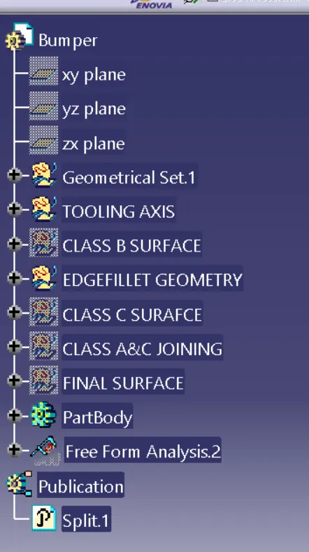
- Ensured Proper Tree Structure.
- Geometrical sets created w.r.t the proper name based on the sketches present inside of it.
- All the sketches are created under the Geometrical set.
- Used the Close Surface feature to make a solid body from the surface.
- Publications: With the use of publication option and published the below things:-
- Tooling Axis
- Class A, B, and C surface
- TOOLING AXIS:-
-
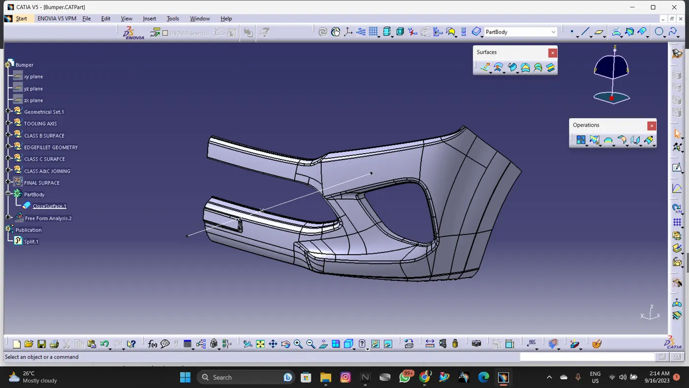
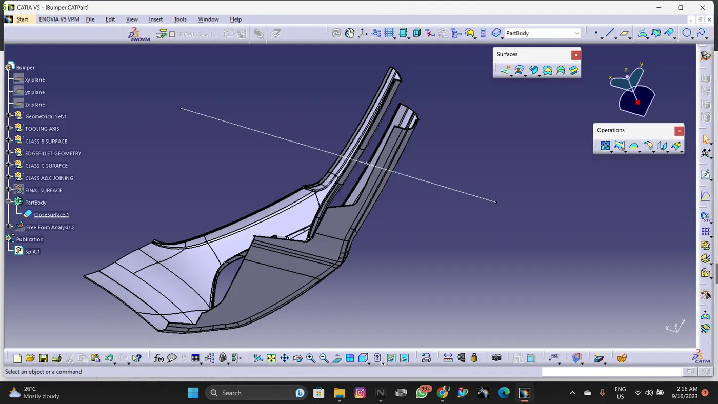
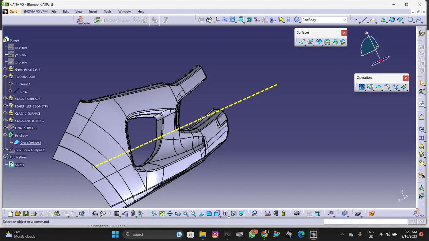
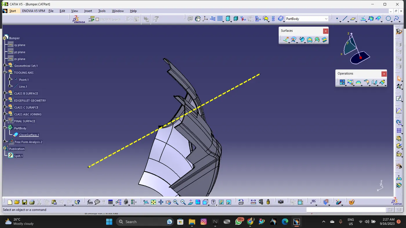
To Create the Tooling axis we've to check the component from the x,y,z direction which direction is feasible to manufacture the component w.r.t the core movement. From the above image x direction is looking feasible to create the tooling axis. Just selecting the bottom upper surface edge of the given class A of the bumper and a point is created over the surface edge after that line is created using point direction method and perfomed draft analysis it's clearing the draft analyis showing positive draft angle of 3deg over the A surface then the line is cosidered as Tooling axis.
-
CHECKING THE INPUT - A SURFACE:
The A-surface or the styling surface is first checked for any gaps and other issues in its surfaces. This Surface acts as the input surface so any correction to be done should be with approval from the styling team or done by them. A- perfect surface is the one when a boundary is created, the lines are only on the edges of a component and its holes or cutouts as shown below.
-
DRAFT ANALYSIS OF A SURFACE:
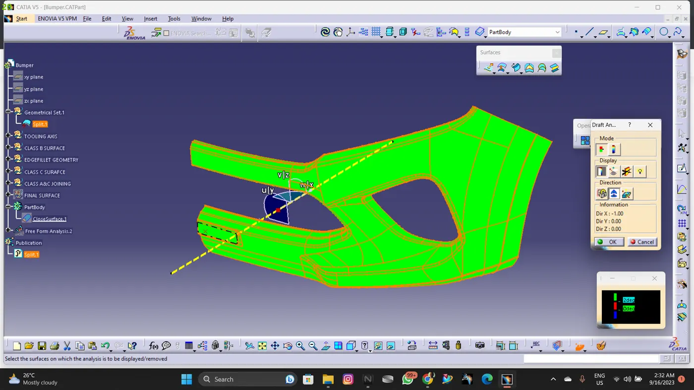
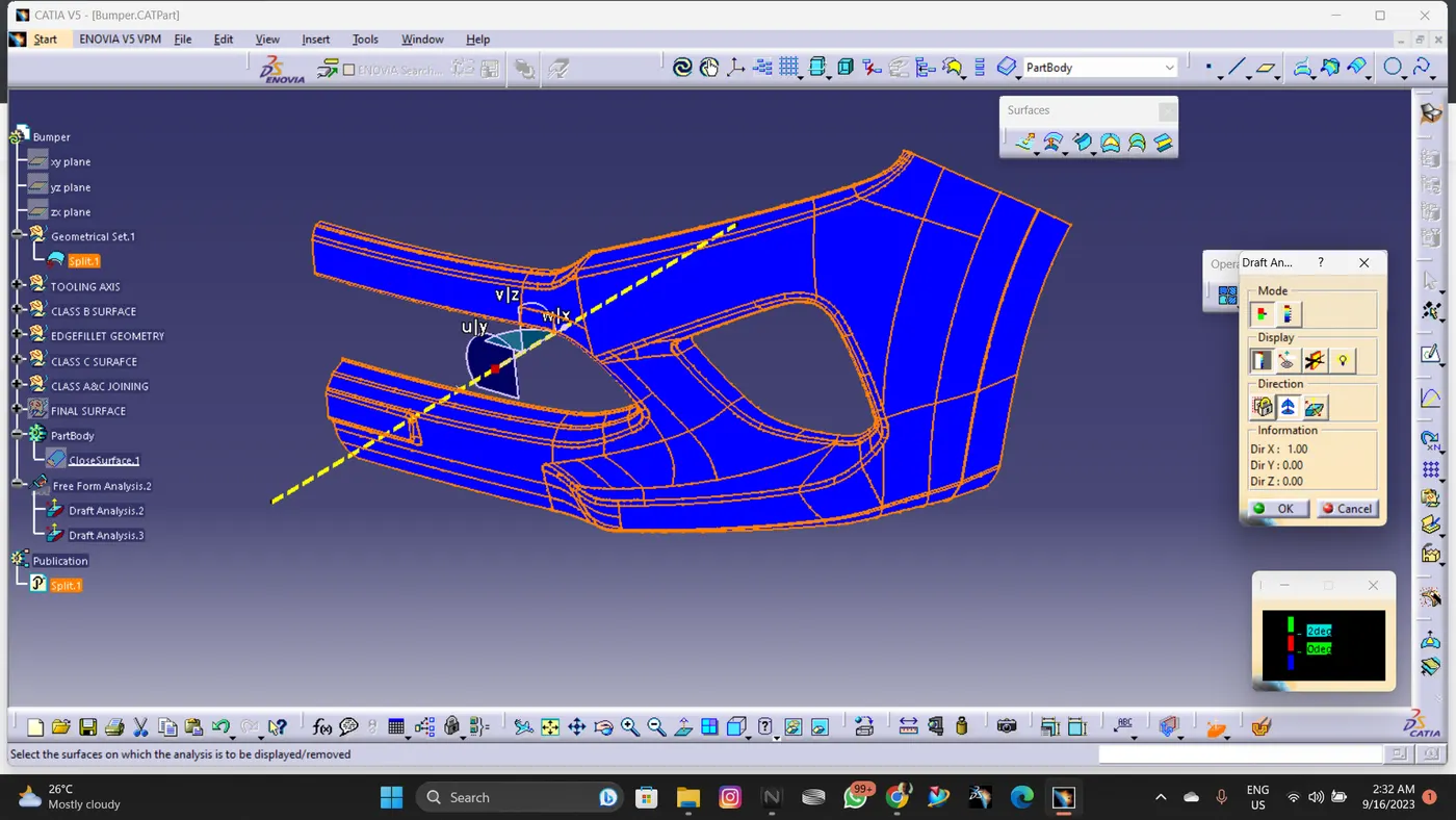
Draft analysis of the surface is carried to check if the surface or part can be manufactured with the required draft angle.
Draft angle is needed for the component to clear the core and cavity surface as it would have shrunk towards the center while cooling.
The draft angle in this design is 3 degrees. As A surface is a single surface there won't be much difference in color.
-
CREATION OF B-SURFACE :
The A-surface is offsetted by 3.00mm as it is the thickness required.
The Areas where the B-surface has issues are corrected by closing them using commands like Multi section,Sweep,Offset and extract.
Finally all the created surfaces are trimmed or joined together with offset surfaces done earlier. This created a single single surface which will act as the final B-surface.
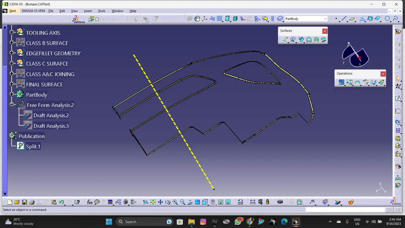
B surface created is checked for any gaps or errors by creating a complete boundary.
-
CREATION OF C-SURFACE :
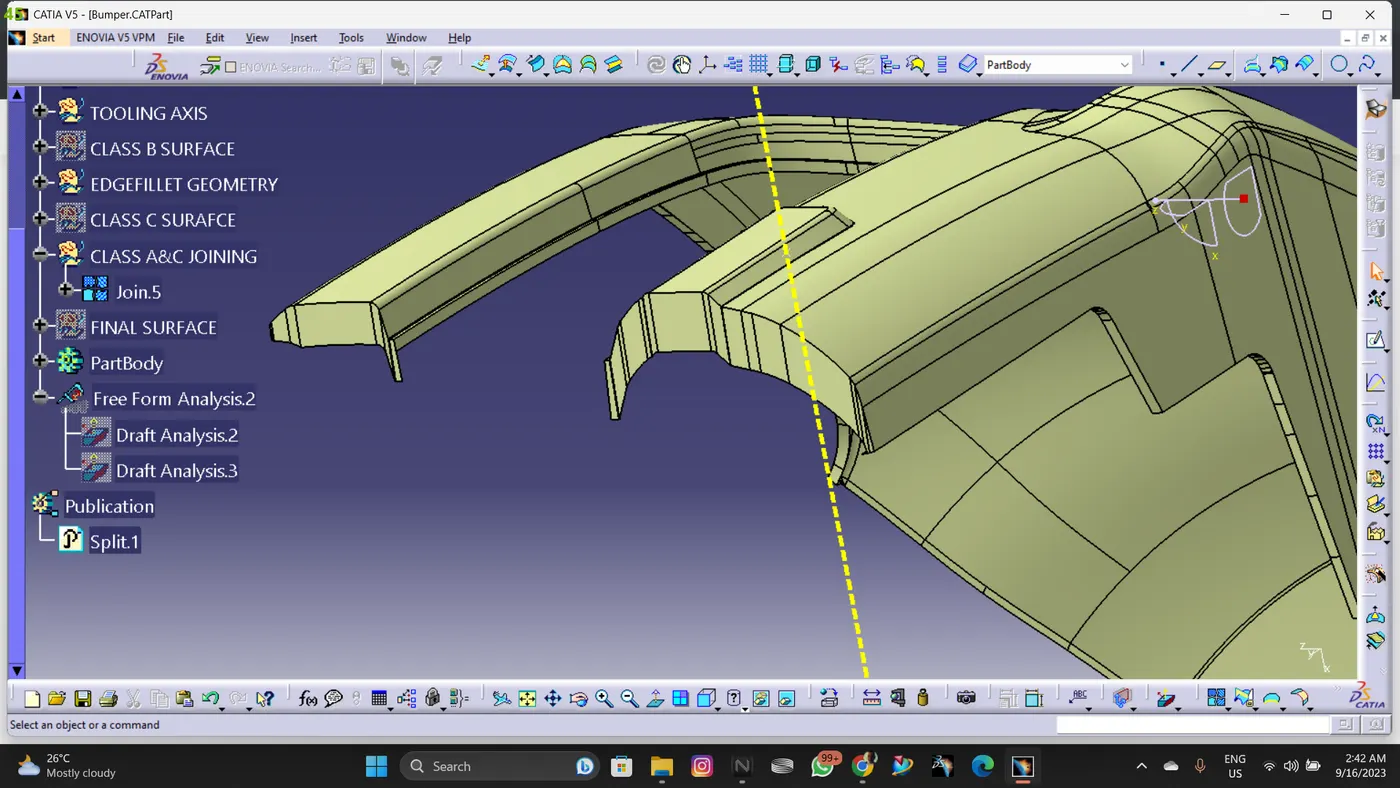
The A and B surfaces are connected by another single surface which is called the C surface.
It is created by using sweep with A surface acting as the reference surface and curve created from the boundary of the same surface.
Sweep with draft direction is also used to create A-surfaces.
Following is the picture of Class A + Class C surface trimmed together
-
-
CREATION OF CLOSED BODY :
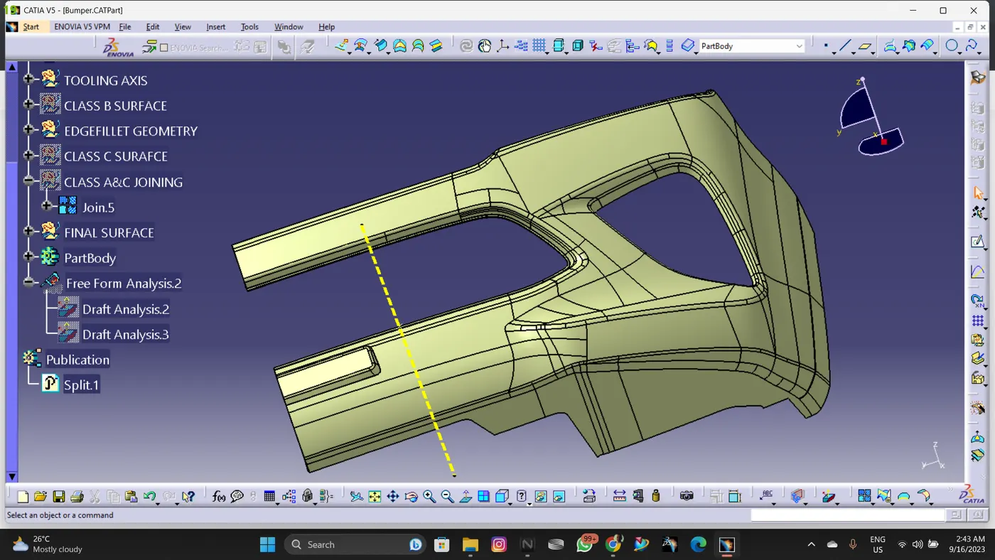
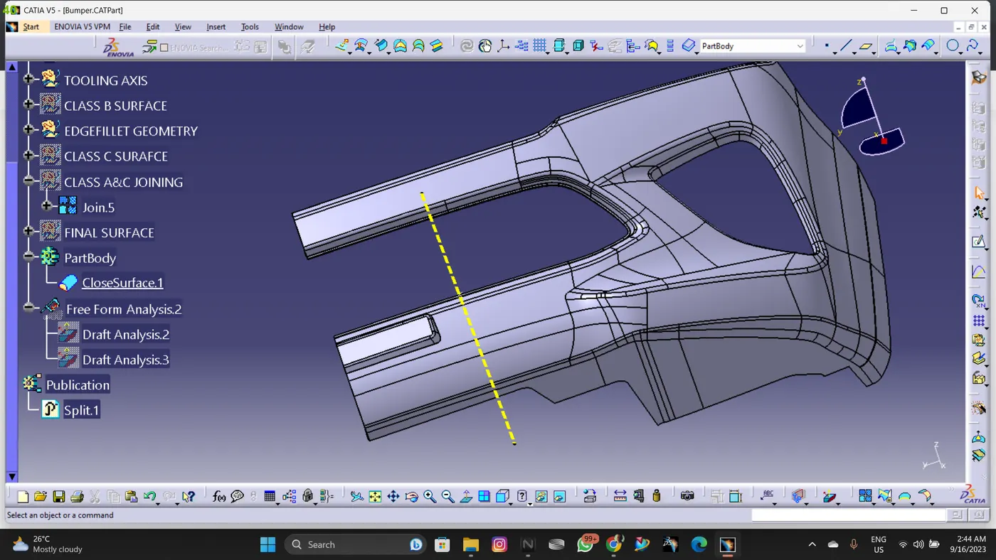
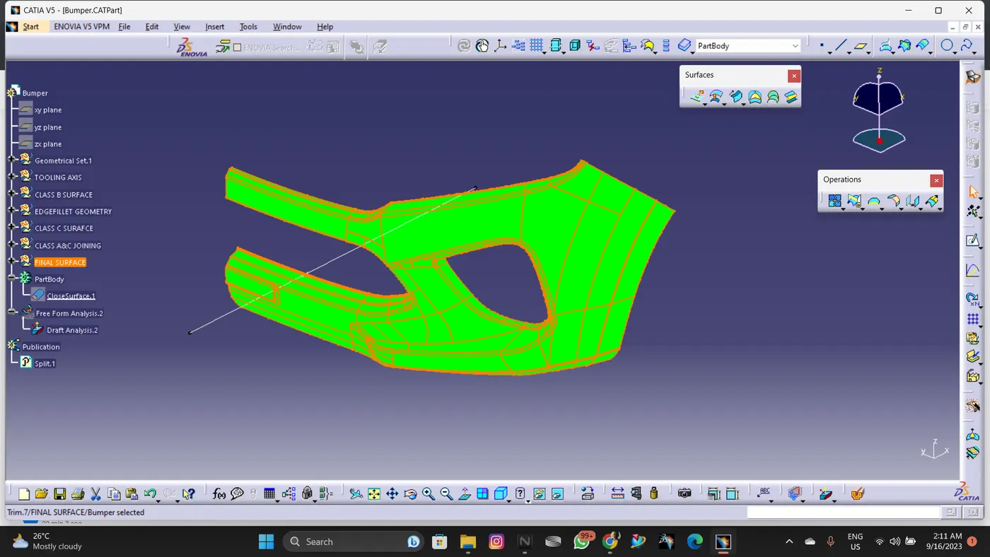
All the surfaces (A,B,C) are joined together to form a closed body.
Boundary is selected and the body is picked. Since an error popped up it can be understood that all surfaces are joined with each other to form a proper closed surface body.
Finally in part design workbench, using close volume it is changed to a solid body.
- MODEL TREE:
- DRAFT ANALYSIS:-
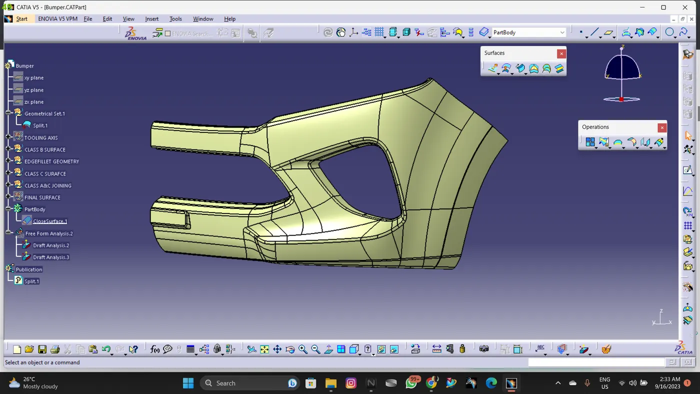
- The Draft analysis for the class A & final model Surface are showing positive draft angle. C Surface which is parallel to tooling axis here i've made a sweep with draft direction , C Surfces which is perpendicular to tooling axis , sweep done with reference surface and 90deg angle which will be touching the bottom or top of the core & cavity. In particular area of the C surfaces are having draft angle of 2.5deg, the sweep was created with respect to the draft direction and tooling axis , it is the half part of the bumper so all the other areas are having a draft angle around 2.8deg.
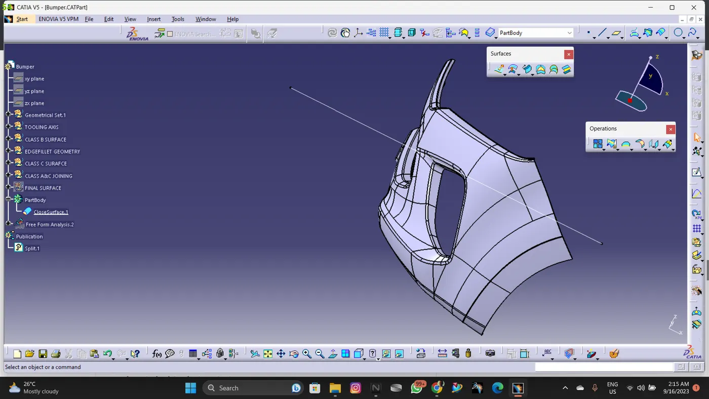
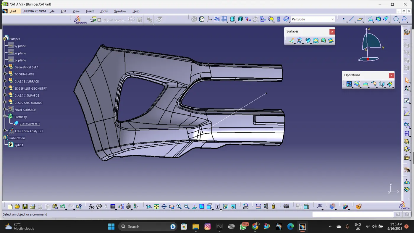
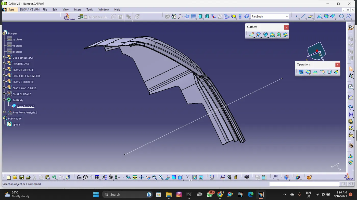
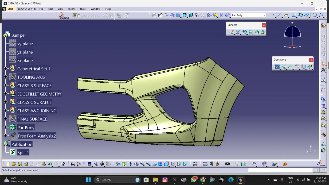
- Views from the different orientations of the Bumper Part Body: