Week 9 Challenge
AIM:-
To Complete the energy management strategy model with battery, UC and fuel cell for the positive power and distribute the power demand among these components. Set simulation stop time to 598 sec.
Objective:
To build an energy management strategy model to distribute the positive power demand among battery, Ultra Capacitor and Fuel cell.
in recent years' vehicles come with two power sources like Battery and Fuel cell, or Battery and Ultra Capacitor, in such case energy management technique plays a vital role in selecting the energy source for different power demand. It is also responsible to maintain the state of charge of the power source to its nominal SOC level.
This article will describe you on how the energy management strategy work to provide input to all the power supplying.
Energy Management Strategy(EMS):
The vehicle industry is experiencing a technological revolution in the powertrains of vehicles. A hybrid electric vehicle (HEV) is an effective choice to solve the problems of the low energy density of a power battery and the short driving distance of an electric vehicle (EV).Different configurations of HEVs have different control strategies, production costs, and applicable conditions.
However, for any configuration, the ultimate goal is to achieve the comprehensive optimization of the efficiency of the engine and the motor so as to improve the vehicle’s performance parameters such as economy, emissions, and durability.The procedure of realizing the goal is commonly called an Energy Management Strategy(EMS).
The act of load sharing is mainly implemented through the EMS systems. According to the power demand of vehicle the power request from sources distributed among different energy givingsources like ultracapacitors,batteries and fuel cells based on their power demand capability.
Process flow of EMS:-
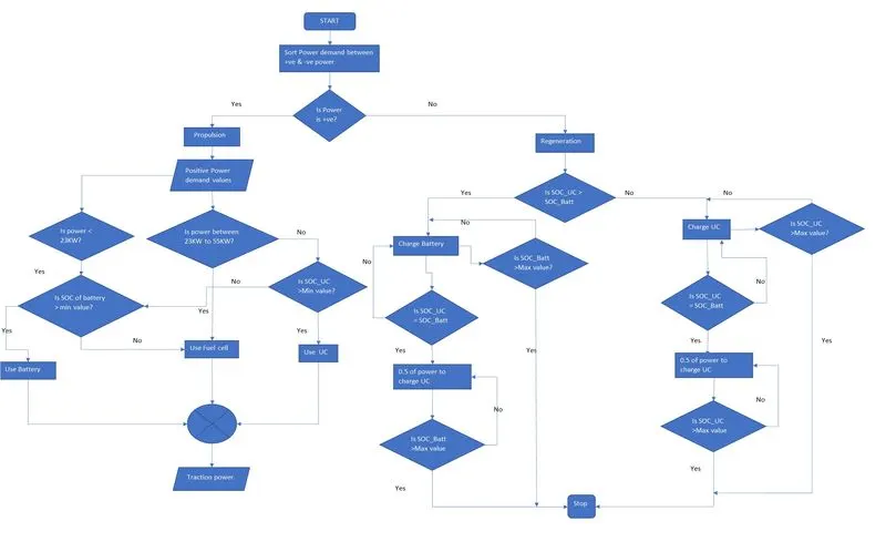
Before creating the simulink model of EMS, the process flow of power sharing mechanism was implemented in a flow chart.
Power Sharing:-
The fuel cells having a range of operating condition to produce the power needed for propulsion.Here we are taking fuel cell with have capability to produce power in the range of minimum 23KW to maximum 72KW. But for better effeciency of fuel cell power usage it is derived that fuel cells will operate at maximum efficiency in moderate power generation area as seen from polarization curve.Thus we are considering lesser power production level for maximum fuel cell power generation as 55KW.Batteries are prefered to operate in lower power demand conditions and ultracapacitors are prefered to operate in peak power demands.
Thus we are get the final power sharing between three components as:
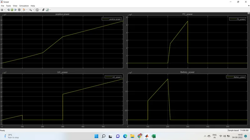
- From 0 to 23 KW is drawn from battery unit based on its SOC condition.
- Above 23KW to 55KW will be drawn from fuel cell power.
- And above 55KW will be drawn from ultracapacitors based on its SOC condition.
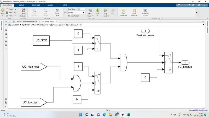
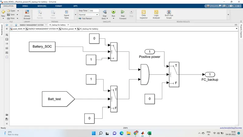
- If SOC of UC is not enough to supply required power demand,in that case the power is drawn from battery as battery backup.
- If SOC of battery and UC are not enough to supply power demand, in that case alternate source is only fuel cell.Power is drawn from fuel cell as fuel cell backup. But at this operating conditions, the overall efficieny of vehicle is reduced as fuel cell can't support with full efficiency for peak power demands and lesser power demands.
devices to run the vehicle. Energy management technique is
followed based on the following criteria:
Power demand Condition SourcE
If UC-SOC >35% Ultra Capacitor
0-9999
If UC-SOC <35% Fuel cell Battery
If Battery SOC>35% Battery
10000-22999
IF SOC<35% Fuel cell
23000 54999 No condition Fuel cell
If UC-SOC UltraCapacitor
55000 and >35%
above
If UC-SOC <35% Fuel cell
SIMULINK MODEL FOR ENERGY MANAGEMENT SYSTEM:-
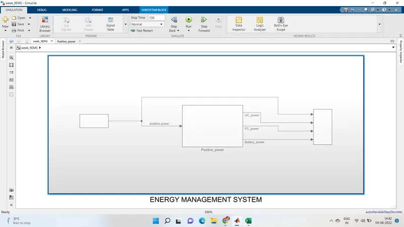
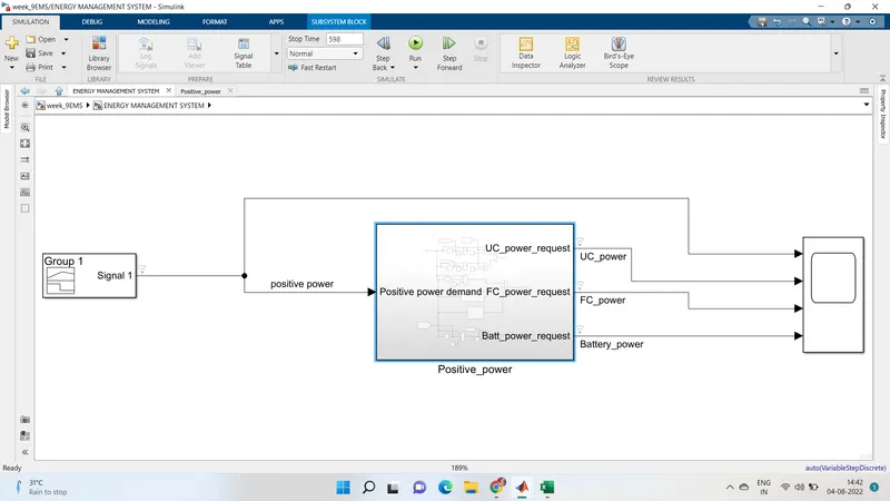
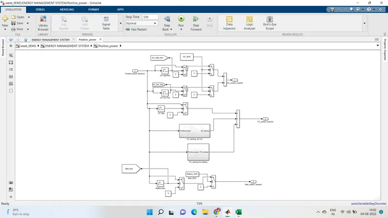
subsystem block of positive power:-
condition for FC TEST:-
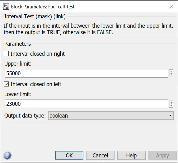
In propulsion subsystem(positive power) the power demand is tested for three components UC,Fuel cell and Battery based on their operating ranges using 'interval test' block as shown below,
For fuel cell test,operating range set as from above 23KW to 55KW.
Condition for UC high test:-
If the condition is true then the output of this block is 1.This output is checked with a switch block as input where, if the input is 1 then this positive power is considered as fuel cell power request.
For ultracapacitor test,operating range set as from above 55KW.
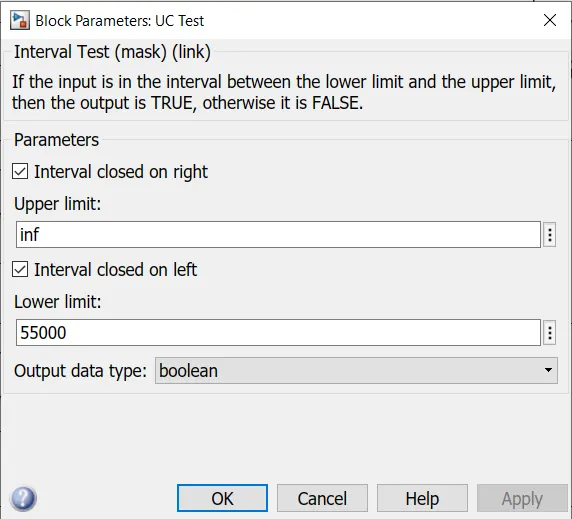
condition for UC low test:-
If the condition is true then the output of this block is 1.This output is checked with a switch block as input where, if the input is 1 then this positive power is again checked for UC_SOC condition.
If the SOC of UC is >= its minimum value, then this positive power is considered as ultracapacitor power request.
For battery test,operating range set as from 0 to 23KW.
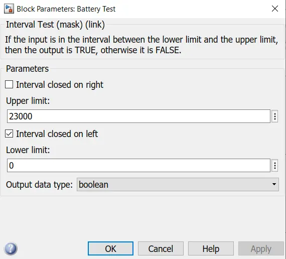
If the condition is true then the output of this block is 1.This output is checked with a switch block as input where, if the input is 1 then this positive power is again checked for battery SOC condition.
If the SOC of battery is >= its minimum value, then this positive power is considered as battery power request.
MATLAB workspace to load the simulink:-
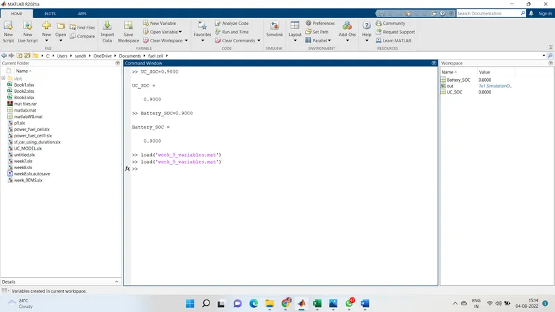
subsytem block of FC_back up for UC:-
Subsystem block for FC_battery for battery:-
OUTPUT:-
CONCLUSION:-
Hence,the to Complete the energy management strategy model with battery, UC and fuel cell for the positive power and distribute the power demand among these components. Set simulation stop time to 598 sec of simulink has been verified.