Week 9 - Challenge 2 - Switch Bezel Design
Design and Draft Analysis of Switch Bezel
Aim: To Create a Switch Bezel Plastic Component through a given Class A Surface and perform Draft Analysis on the Final Plastic Component.
Introduction: : The switch bezel is a crucial component of the automotive control panel. It serves as the frame that secures the switch covers and buttons. The moulding process is the preferred manufacturing method for creating plastic trims in the automotive industry.This report details the design considerations, creation of tooling direction, surfaces, and draft analysis required for the switch bezel design.
Specifications:
Switch Bezel Thickness = 2.5mm
Minimum Draft Angle = 3 Degrees
Design Considerations:
- Class A Surface: The Class A surface should be aesthetically smooth and visually appealing, as it is the exterior of the part that is visible to users. The appearance should be flawless, with no defects that could impact the part’s finish.
- Class B Surface: The Class B surface includes all functional features such as ribs, supports, and reinforcements. It plays a significant role in the part's structural integrity.
3. Class C Surface: The Class C surface is responsible for ensuring the correct ejection of the part from the Mold. It should also pass the draft analysis to avoid difficulties during the manufacturing process.
Creation of Tooling Direction:
The tooling direction is critical for the proper ejection of the switch bezel from the mould cavity.
The process to establish the tooling direction follows these steps:
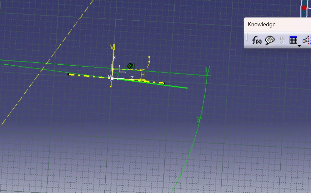
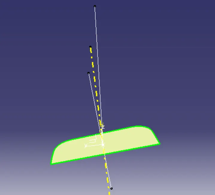
- Extracting Base Surface: The base surface of the Class A surface is extracted, and a point at the centre is created. An axis system is then inserted, with the current feature temporarily disabled.
- Projecting Intersection:
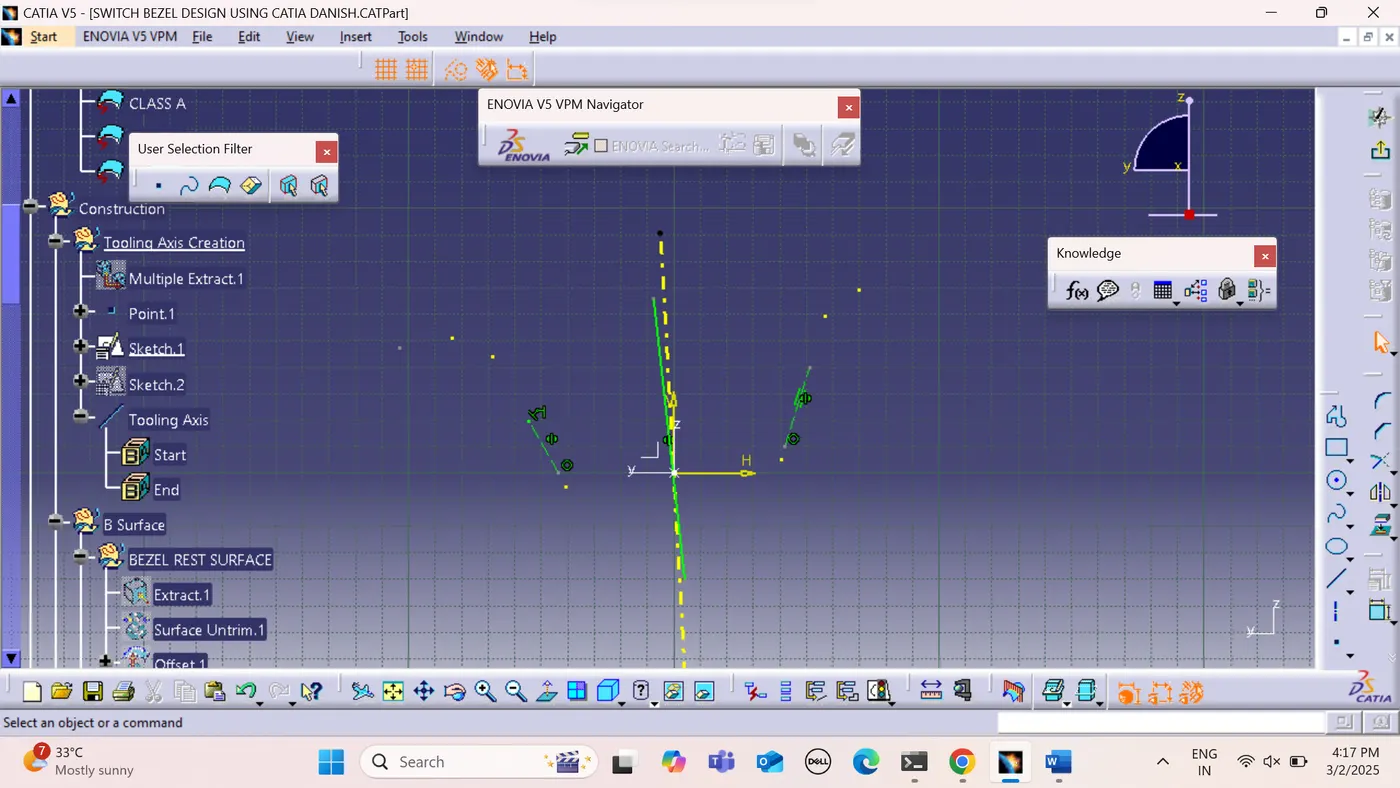
- The intersection is projected along the YZ plane, and two inclined lines are drawn within the positioned sketch.
- Bisecting lines are then drawn from the two inclined lines.
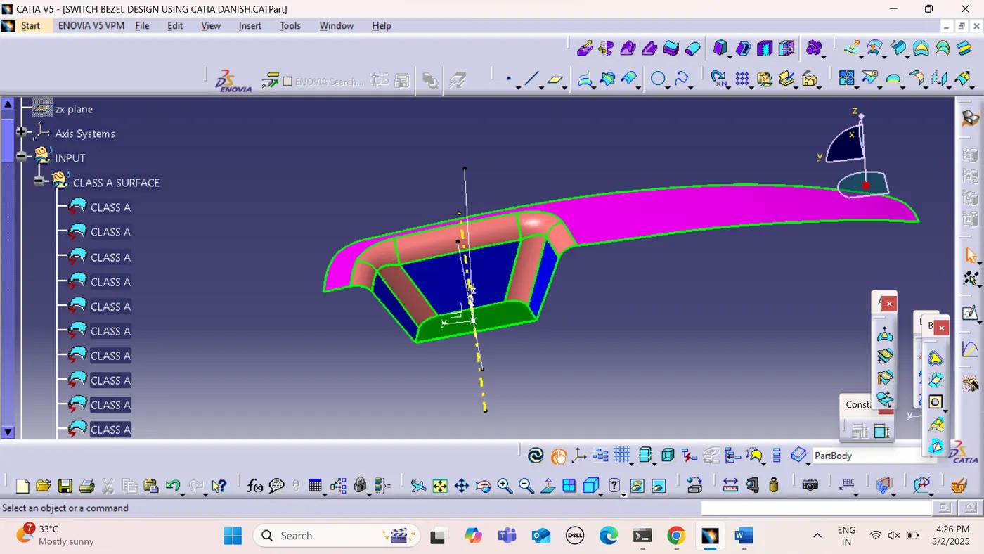
4. Tooling Axis Creation: The bisecting lines from both the YZ and XZ planes are intersected to form the tooling axis, which is then published as the tooling direction.
Creating Class B Surface Creation:
- Using the Extract option select the Bezel Rest from the Class A surface

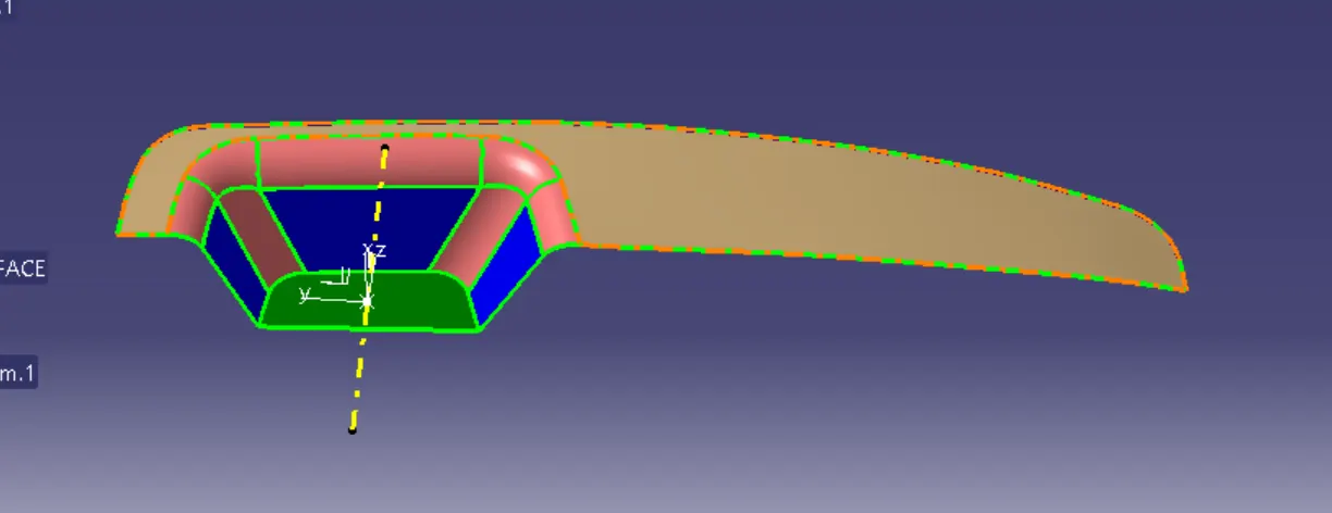
- Similarly we will use extract for sides, and base also.
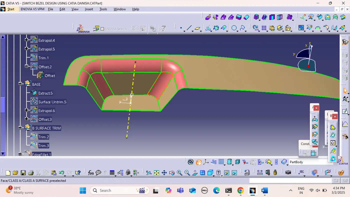
- then use untrim option

to remove trims and get original shape.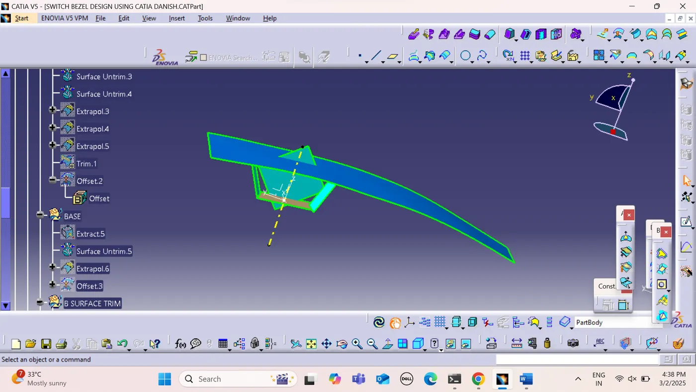
- Then use the extrapolate option

to get rid of any gaps between the intersections.
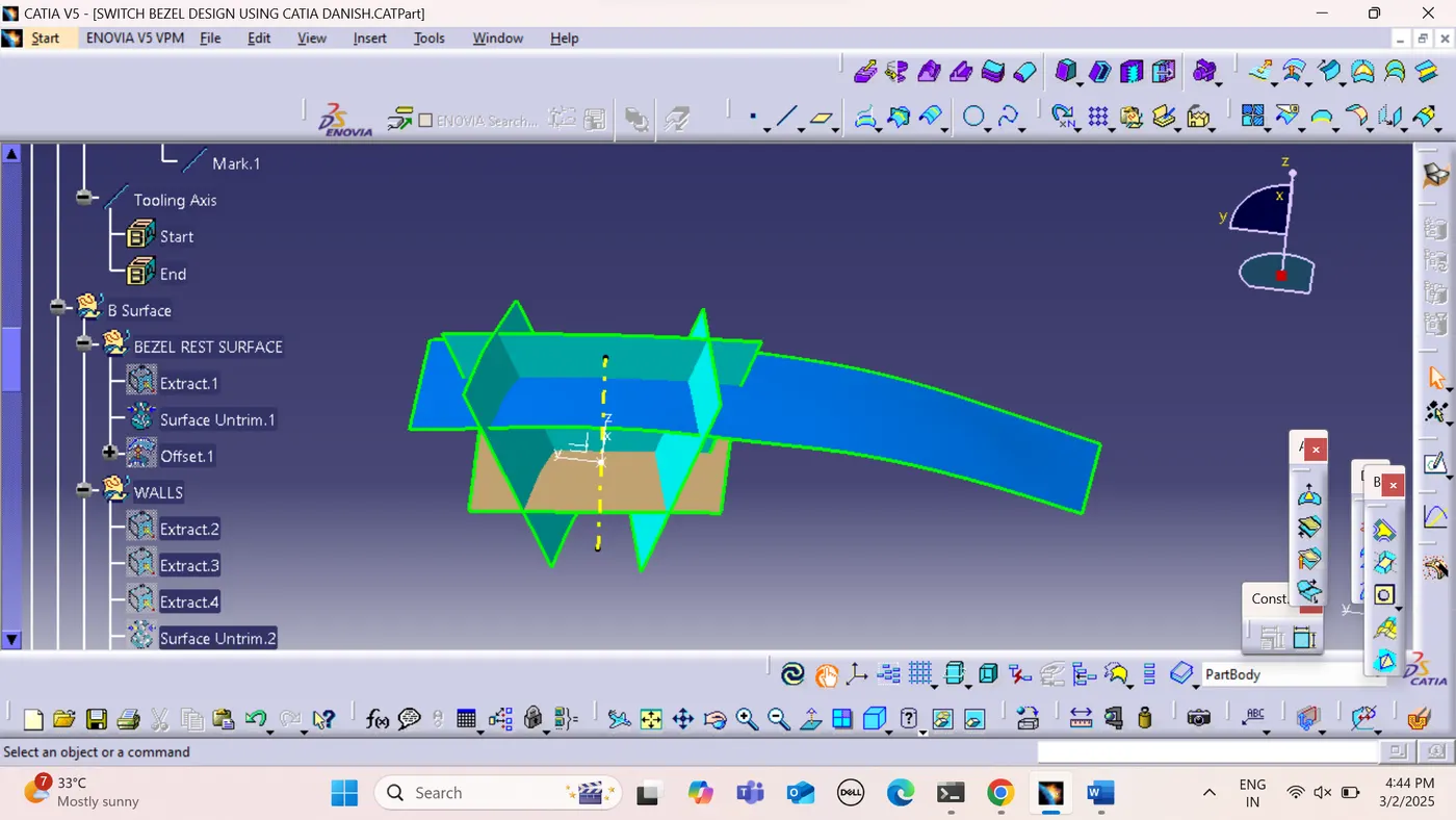
- then give offsets of 2.5 mm for desired thickness.
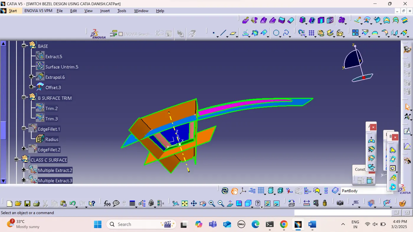
- then use the trim option to get the required shape.
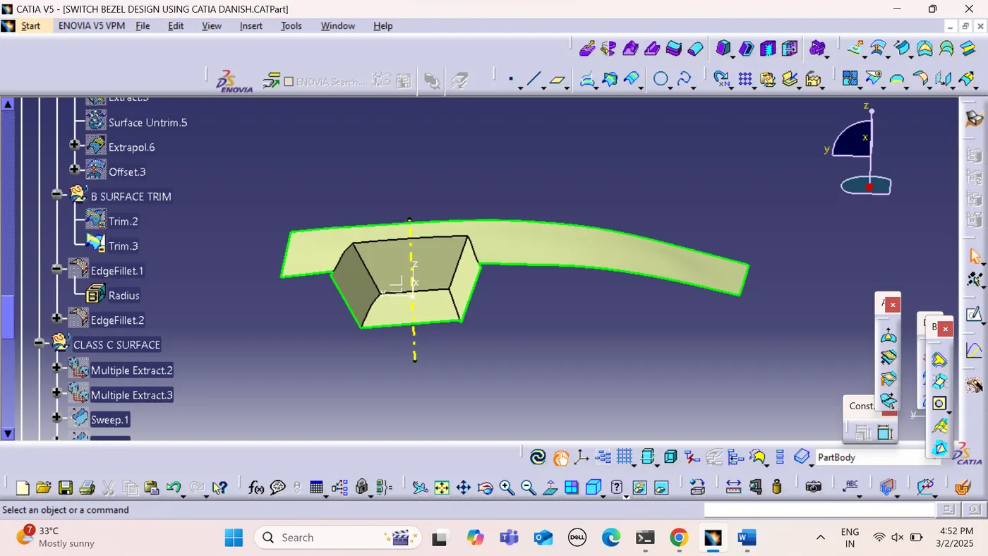
- after this use the fillet option to give the fillets as class A. As we
are giving offset, we have to give radius & thickness for fillet input.
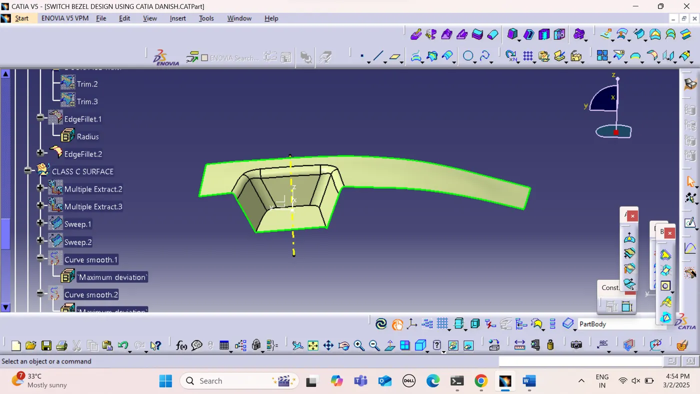
- Use the boundary command to get the edge of the class A.

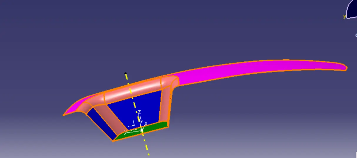
- use the sweep command and give the boundary, tooling axis and draft angle as input to get the Class C Surface.


- Use the join command to join the class C & Class A Surfaces.

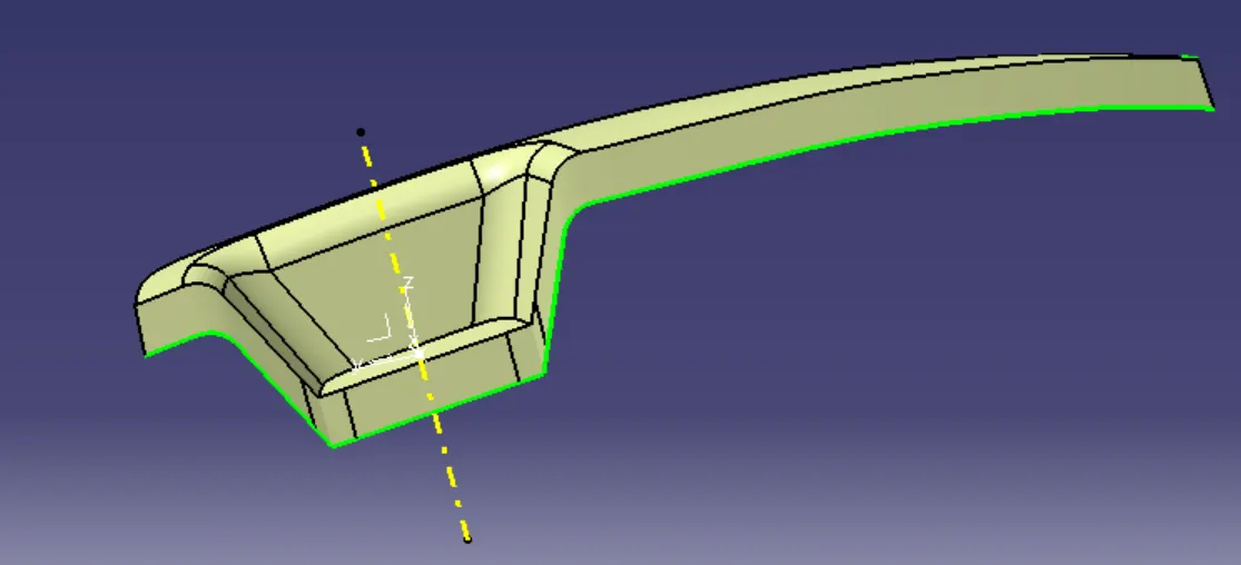
Final Creation:
- Use the Joined Surface & Class B Surface and make a trim.
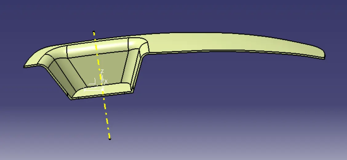
Closed Surface:
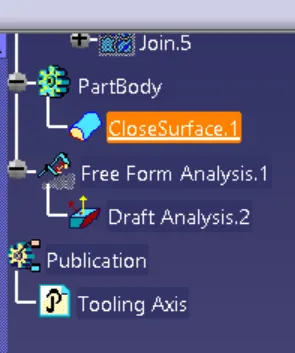
- Go to Part > Body > Closed Surface command and we have a final solid part.

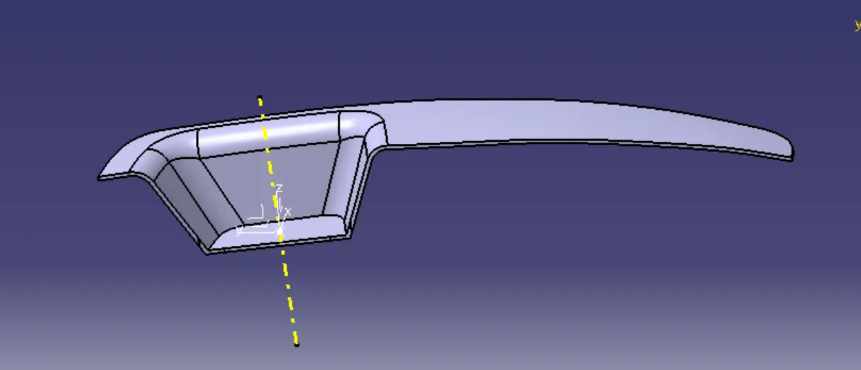
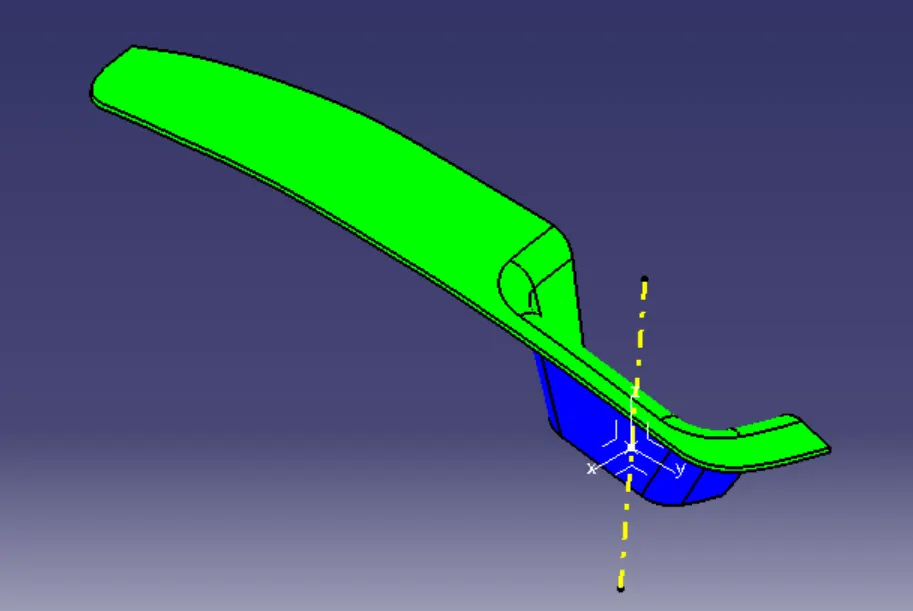
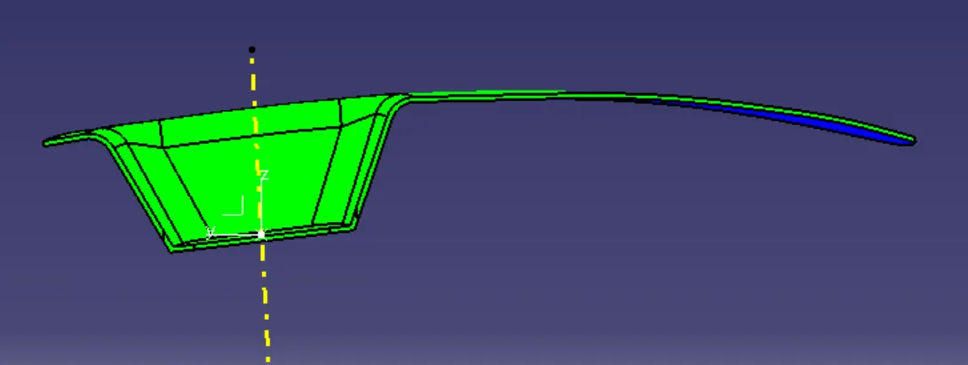
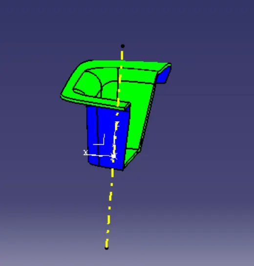
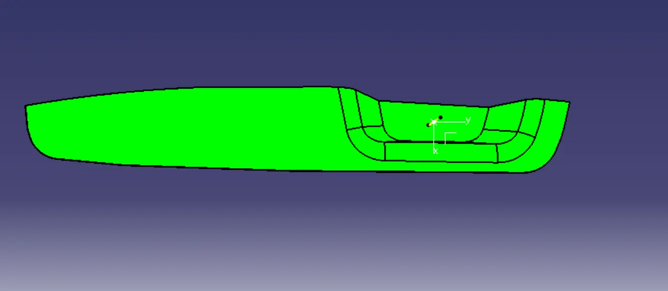
Draft Analysis for Final Closed Surface:
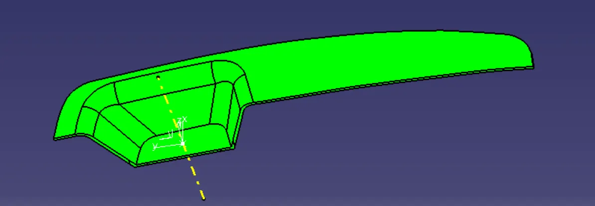
Views:
Isometric:
Front View:
Side View:
Top View:
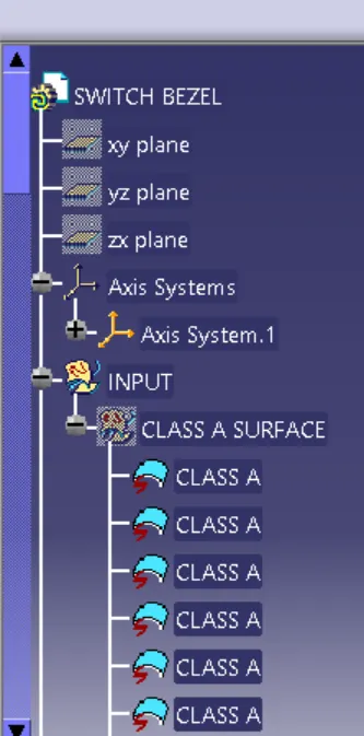
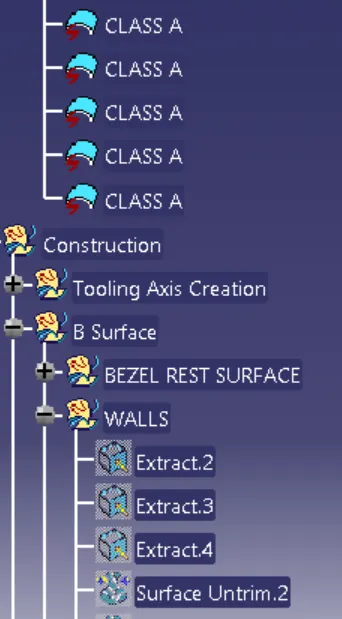
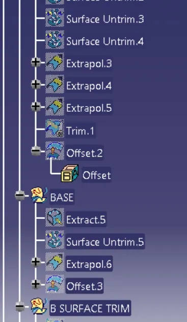
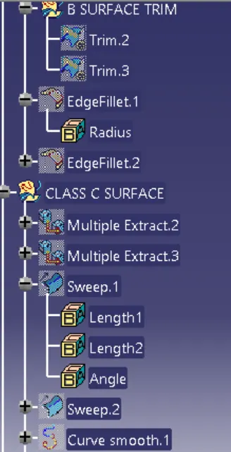
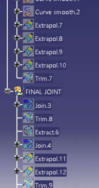
Feature Tree:
Conclusion: Created the plastic component in Catia V5 using the given Class A Surface.
- Created the tooling axis.
- Created the Class B Surface.
- Created the Class C Surface.
- Created the Closed Surface from Surface geometry.
- Published the Class A, B & C Surface, Tooling Axis & Closed Surfaces.
- Did the Draft Analysis.