Week 9 - Challenge 2 - Switch Bezel Design
AIM
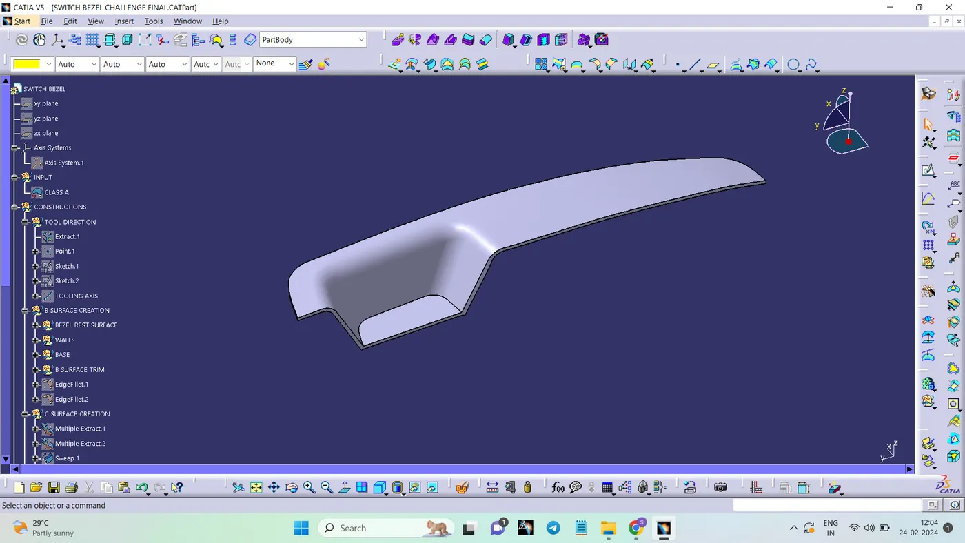
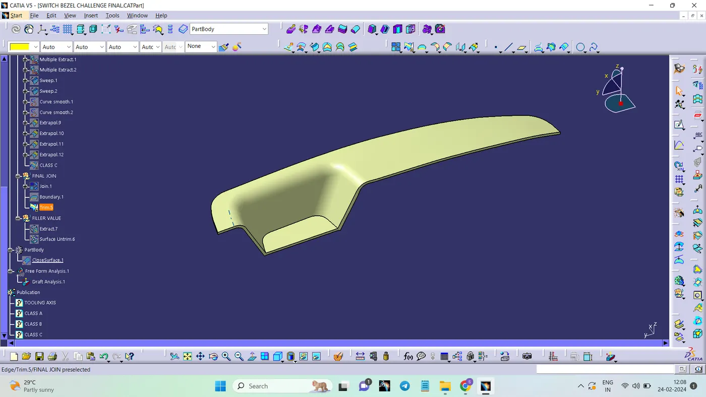
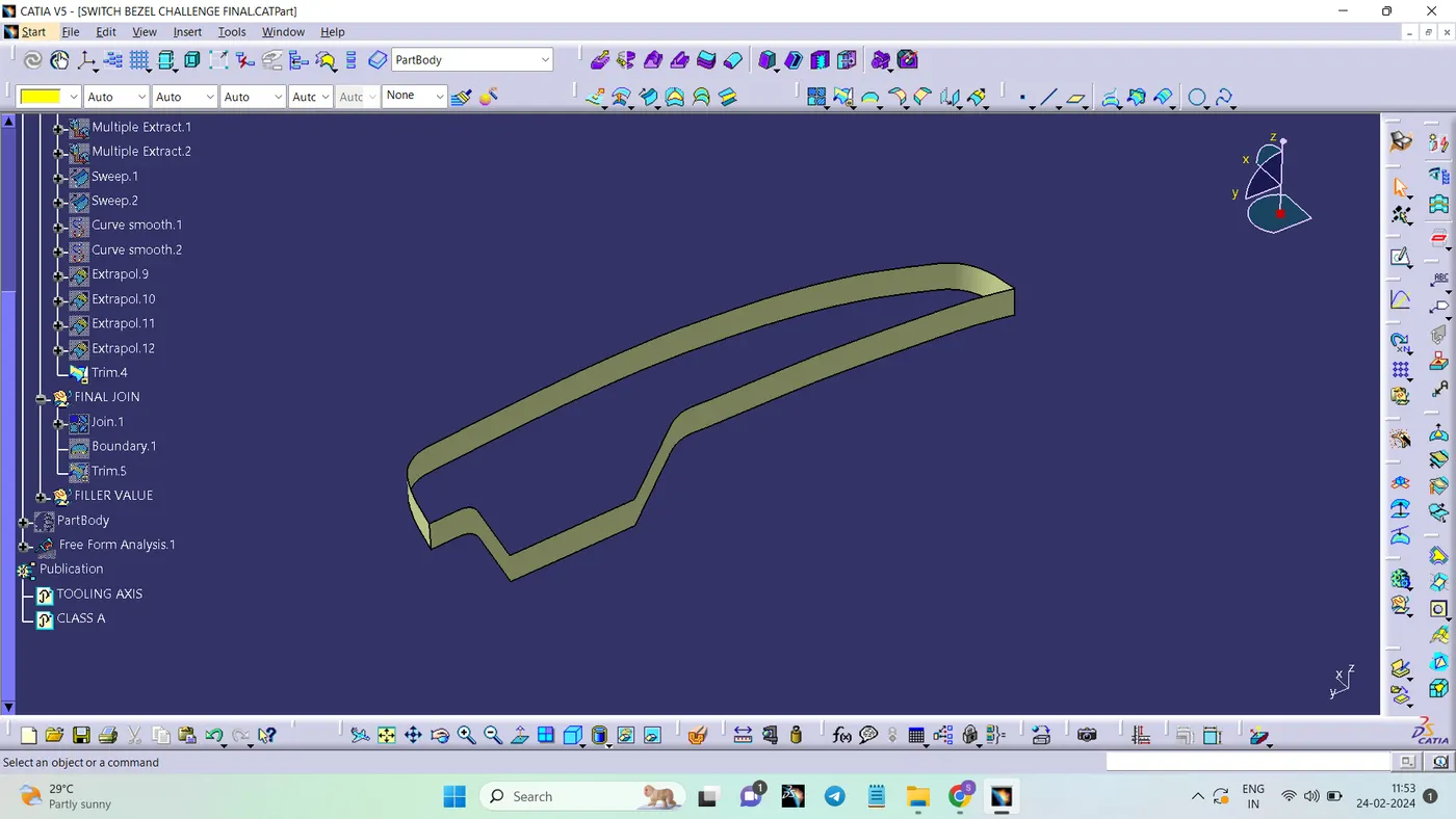
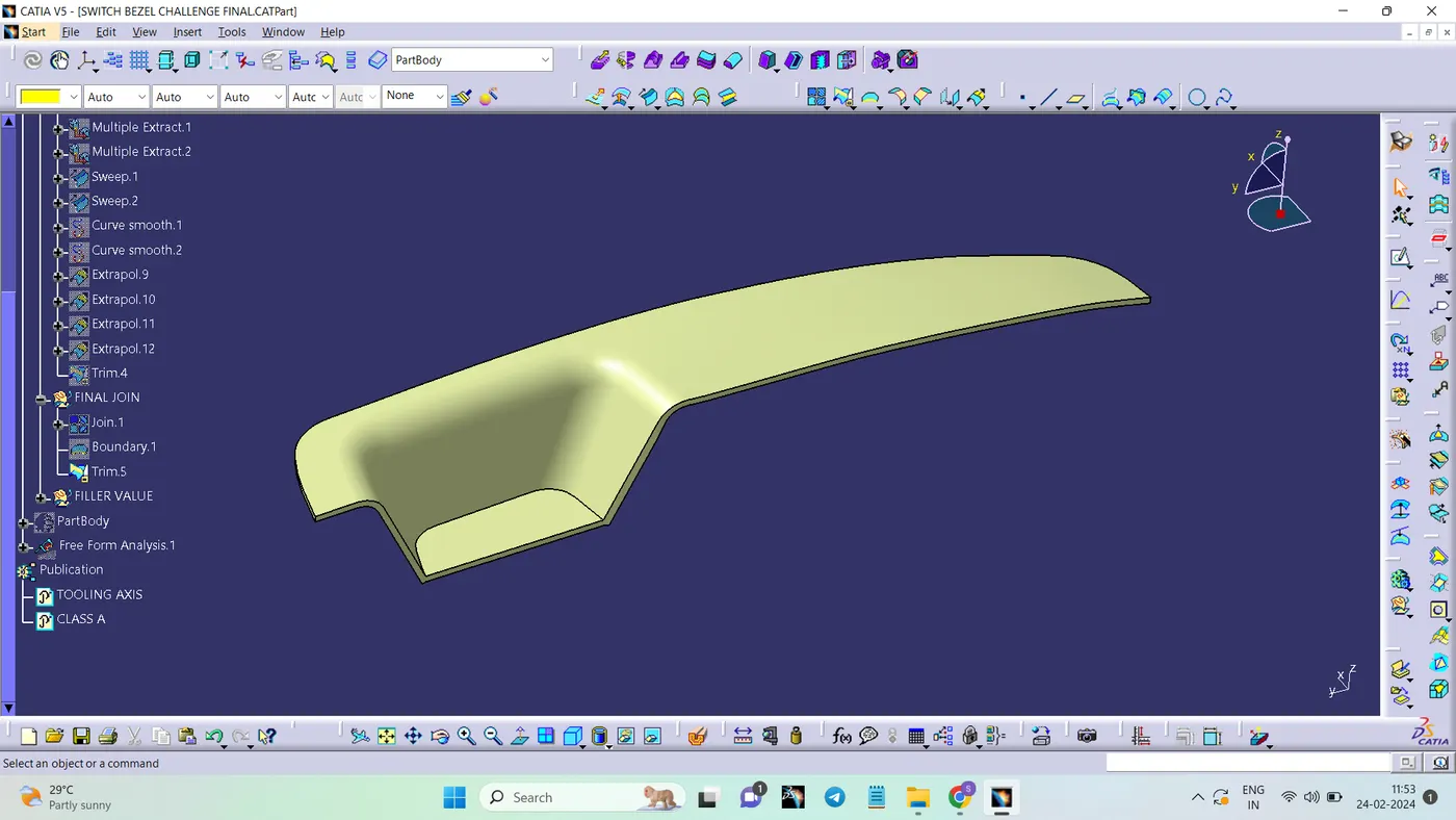
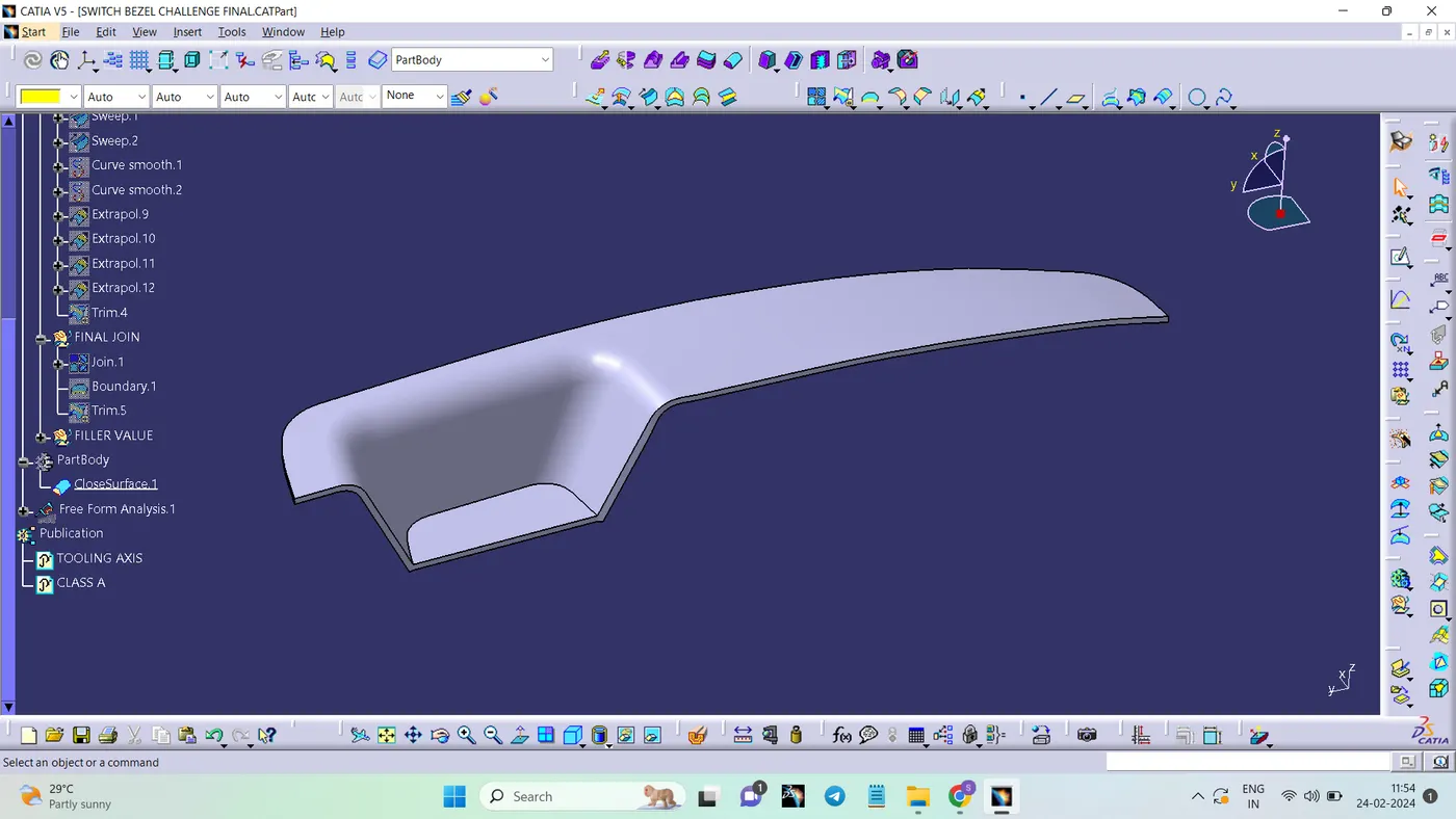
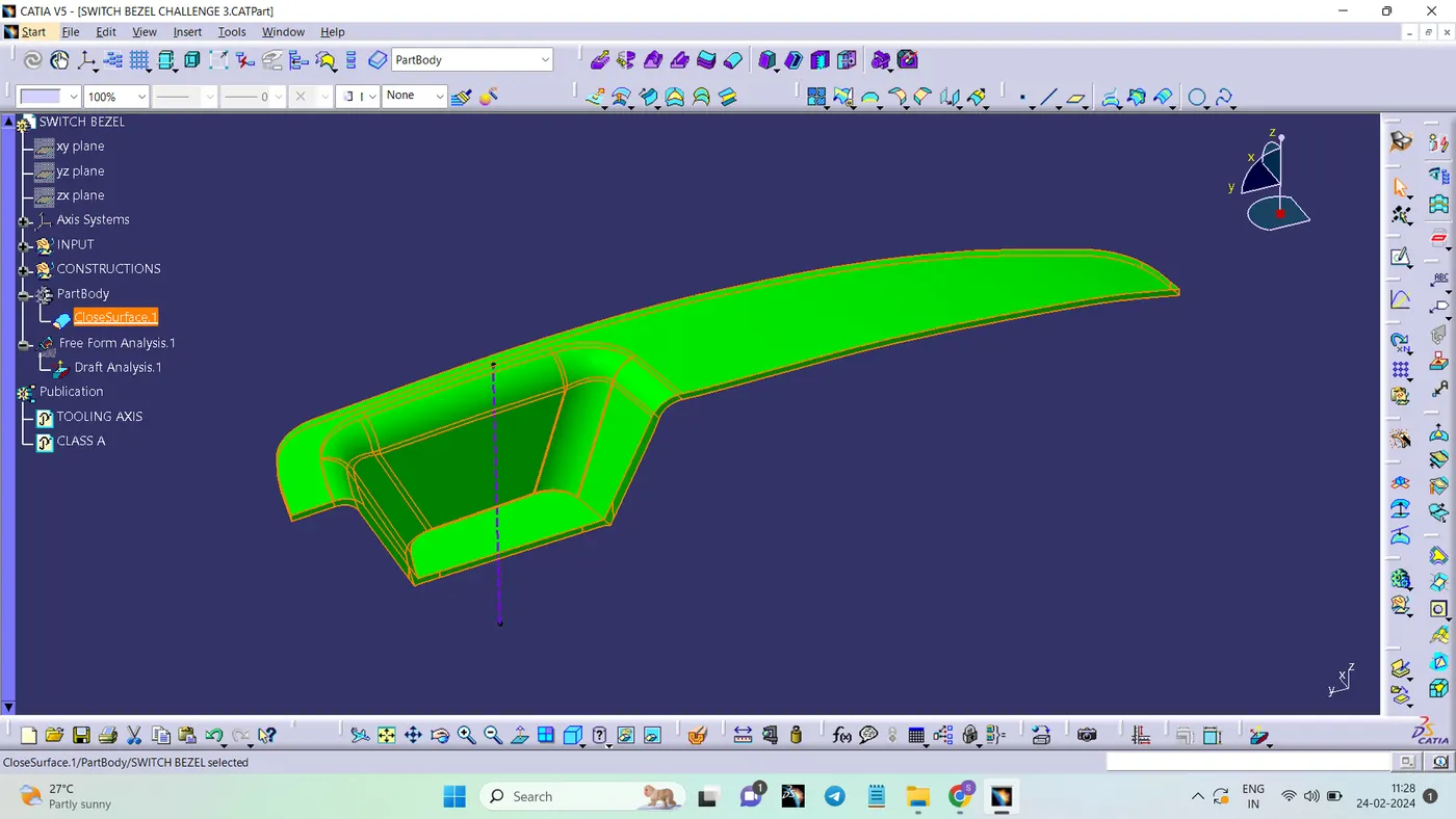
To create the Switch Bezel Plastic component through the given Class-A surface. To begin with, the tooling axis for the given Class-A Surface should be created meeting the requirements of the draft angle and at the end perform the Draft analysis on the model.
CLASS A SURFACE
Class-A surface means visible surface. It gives the aesthetic of the component which is created by the styling team and gives to the part design engineer to create the part with all engineering aspects.
CLASS B SURFACE
Class-B surface means thickness of a part it is not visible and is inside part. In other words, Class-B surface is a surface below a certain thickness from the class-A surface. This is the surface that contains engineering aspects of a model.
CLASS C SURFACE
Surface that joins class-A and class-B surfaces is class-C surface. Class C is often specified for interior surfaces not readily visible, surfaces that will be covered by another part when assembled
TOOLING AXIS
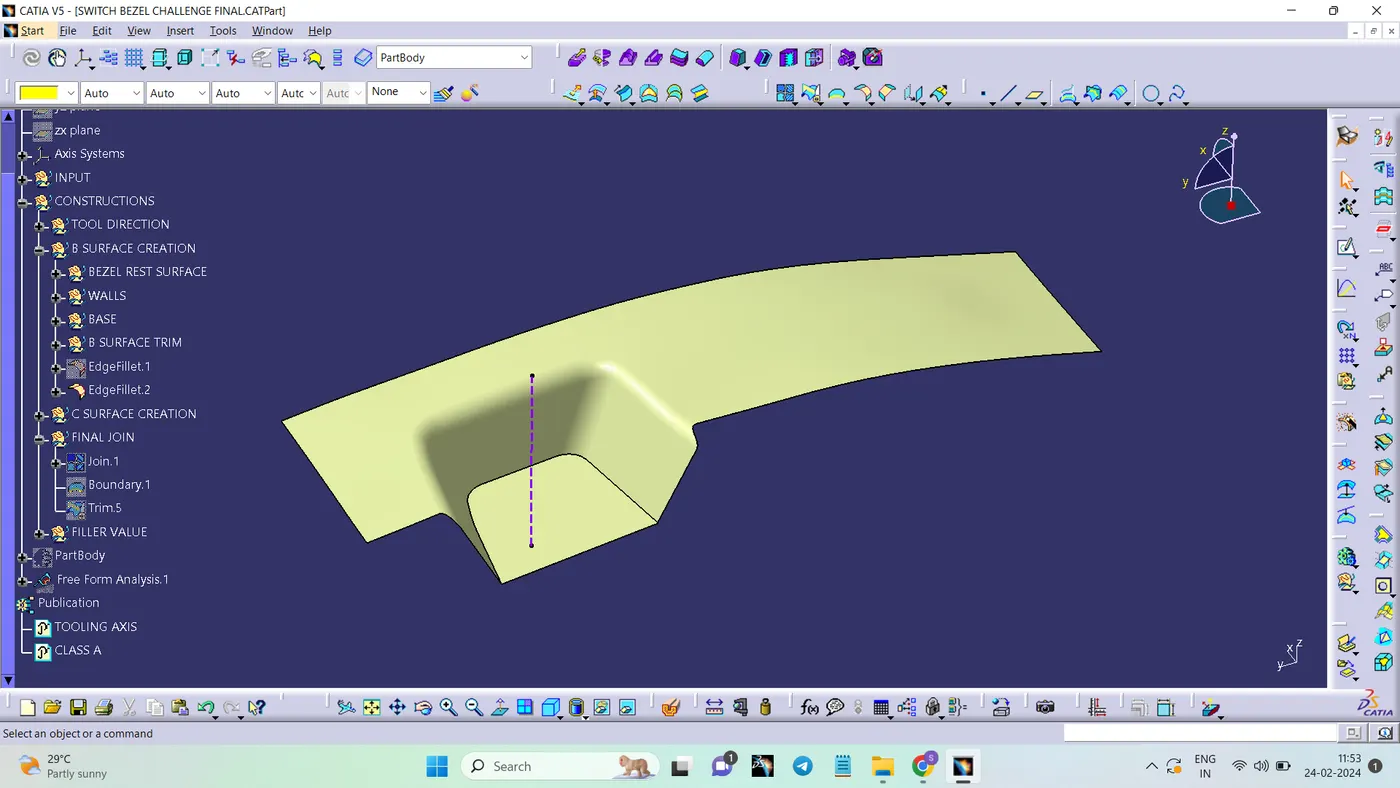
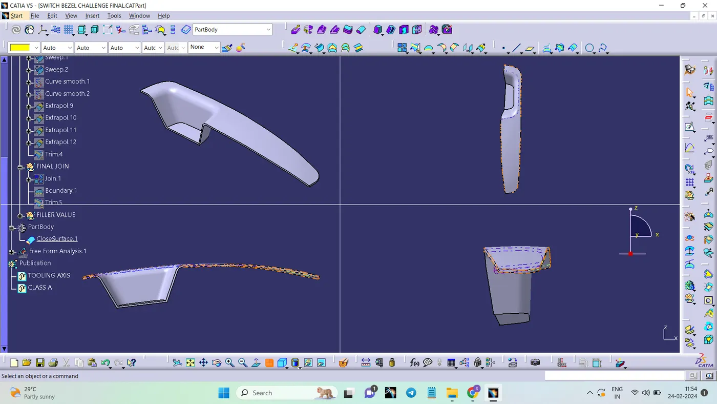
A reference point is created along the Surface zero and new Axis system is created.The X Direction along the Class A and Y direction along the Class A were used to create Tooling direction.Finally, the tooling axis is created by bisecting the two lines and it is published. Class A Surface as input using surface operation commands Class B is developed.The tooling Axis determines the direction of Class C boundary swept with draft direction. When viewing from tooling direction normal all the parts that are drafted should be visible so it gives a rough idea to determine product manufacturing in Injection moulding.
DRAFT ANALYSIS
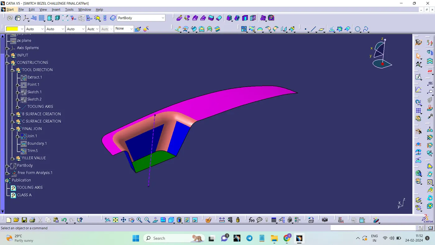
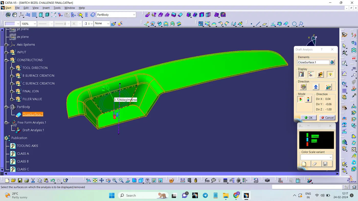
The part created has to be changed to material mode in display frame.Then by enabling compass definition the axis system is pan along the direction of the part and aligned in line with the tooling direction.Lock Direction is applied that fixes the compass and then the mode dialog box is formed by snapping at any point on the part.The Colour Codes are classified and Draft Angle are applied.Then the Running point analysis is used to hover around the part to analyse the permissible draft angles and the analysis is saved
TREE STRUCTURE