Week 9 - Challenge 2 - Switch Bezel Design
Report:
Inputs:
- Class A Surface of the Switch Bezel(STEP File).
- Thickness of Plastic Part - 2.5 mm.
Title - Draft analysis of switch bezel
Objective - To learn draft analysis of class A surface of Switch bezel, forming plastic structure and creating solid surface.
Introduction - In this project we will learn step by step process of draft analysis of switch bezel and creating solid model by class A surface.
Methodology -
-
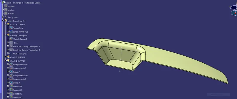
Tooling Axis Creation:
- To create a Tooling axis, firstly i did extract the class A base profile and create point on the surface.
- Then made sketch for side walls center bisecting line for main tooling axis input 1.
- Then second sketch is made of another axis line creation that with taking reference of the angular wall line create for 2.5 Dgree.
- Then finally create Bisecting line with input of both sketch and that would be my tooling axis of the component.
- I have publish the class A & Tooling Axis for easy access.
Below image of the tooling axis of concerned,
Class B and Class C Surface Create:
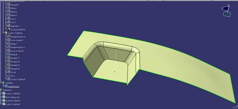
- In order to creation of B surface, firstly i have extract side walls and untrim those all the extrapolate that after that offset those all surface as component thick value as 2,5mm.
- Then Trim all together then made side wall of the surface and same method followed to create base and Bezel rest surface with offset of 2,5mm thick.
- All together trim and finally i got B surface, then colored for easy identification.
- Then i got extract the class A boundary in 2 batches then sweep it, here i got error so i used smooth curve to solve the error and made sweep now tha got C Surface.
- Once after join the C & A then i had check the boundary finding to ensure my profile get closed or not, at that time i got open boundary in front side edge face then i extract the specified profile then trim together then i replace the latest curve with the join input and did update.
- Now i got C surface.
Below picture is B Surface of Switch Bezel,
Final Trim:
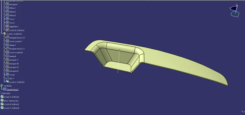
- Once get the inputs of B & C surfaces then i join the Class A & C togther the trim it the results with Class B surface then i got the result of closed surface of the componenet.
Below picture is Final Closed Surface of Switch Bezel,
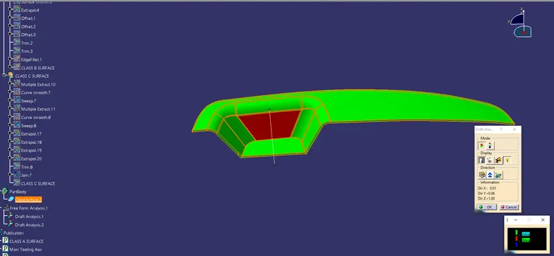
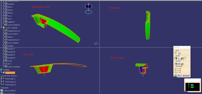
- Draft analysis of switch bezel - open the surface workbench along with class A surface of given component. Then inspect the surface (aim is to find the surface that may create the problem for tooling axis surface which are parallel to Z direction surface.). Now extract the base of switch bezel and create a centre point of the base. Create a dummy tooling axis with the help of centre of three side walls by giving point. now place a YZ plane parallel to original plane. take an intersect with that plane and define a line onto the face project. Now take the intersection of switch bezel in zx plane and define a axis with respect to the axis. Now define a bisector linewith the help of of those two artificially created axis. make sure the angle between two axis (bisecter one and zx plane axis should be in the range of 3-6 degree).
Images of the color scale variant:
- Green color is indicating morethen 3`dgree` angular results
- Red color is indicating inbetween 0 ~ 3 `dgree`
- Blue color is indicating upto Below 0`dgree` or Negative Value.
Solid Body:
Final solid created by inputs of the above final trimed Closed surface of Switch Bezel surface.
The above processed have followed to make the B & C surfaces for final product designing.
Note:
- I herewith enclosed the final CAT Part in Zip format.
- I request to use hide/show to check the hidden surfaces and draft analysis report into the CAT file.