Week 9 - Challenge 2 - Switch Bezel Design
Switch bezel is a car part which contains switches and buttons to control different functions like window control,door lock,media etc. It is located at the inner portion of the door. The procedure used to create the part was same as the base bracket one. Class A surface was used to create the tooling axis. Class B surface was created at a distance equal to the thickness which was the identical surface of class A. Class C was formed as the wall of the model and then all the three surfaces were joined together and draft analysis was carried out.
Steps in detail that are involved to create switch bezel are as follows:-
Tooling axis
- The first geometrical set was created with the name tooling axis and a sketch was created by extract the base and create the point with the base surface after that create line with point . the created line is tooling axis
-
All the sketches were made iso-constrained.
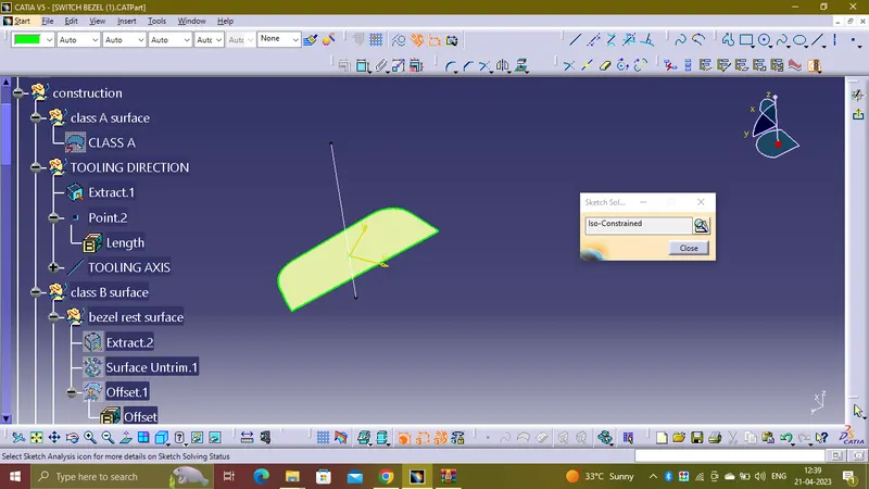
The line which is shown in the figure is tooling axis
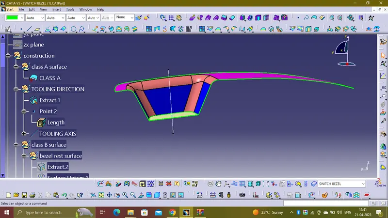
B SURFACE
- A new geometrical set with the name B surface was made and the top, side and bottom surfaces were extracted.
- The same surfaces were untrimmed and later extrapolated to carry out trim command in between them perfectly.
TOP SURFACE
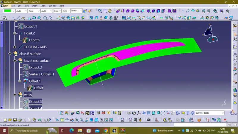
SIDE SURFACES
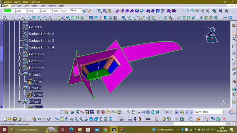
BASE SURFACE
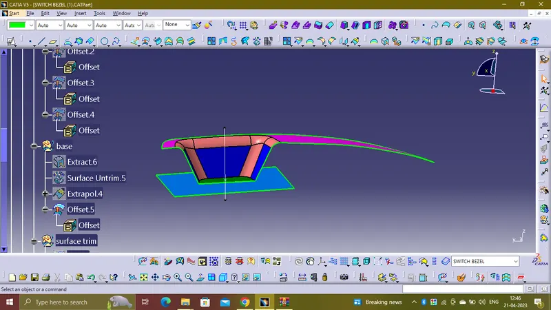
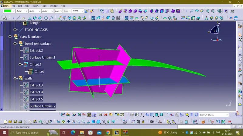
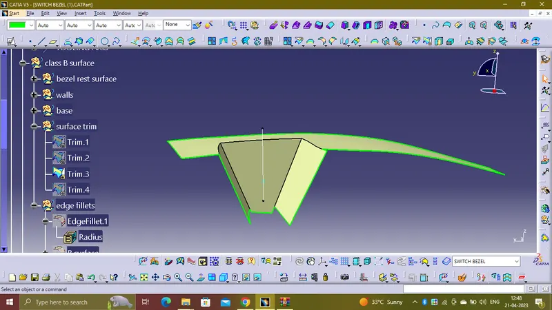
- After getting the surfaces, it was trimmed and made to form a single surface.
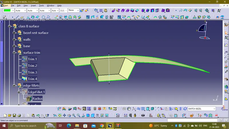
EDGES RADIUS
- The fillet radius was obtained by measuring the same and later it was given the B surface at the same region as seen on A surface. The value given for fillet was radius - thickness i.e. 15-2.5=12.5mm and 14-2.5=11.5mm.
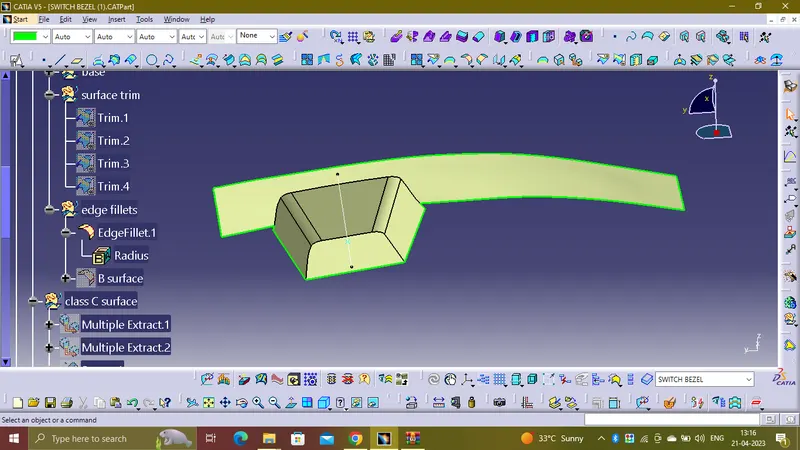
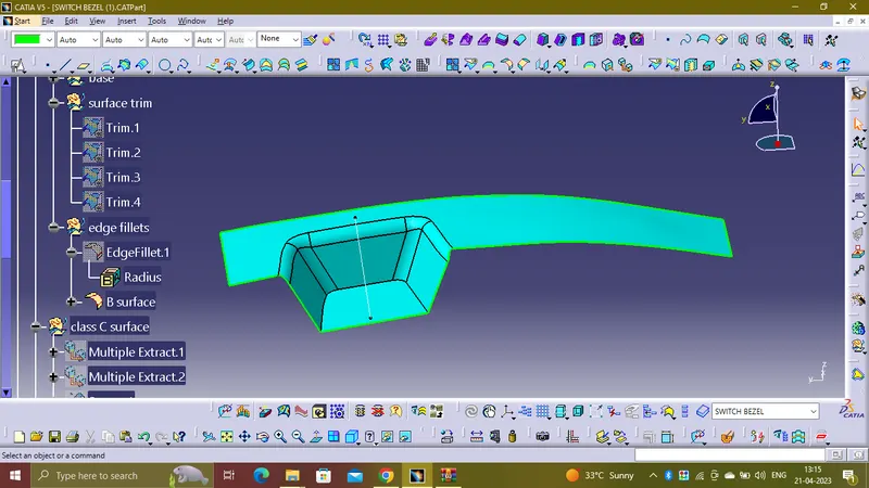
C SURFACE
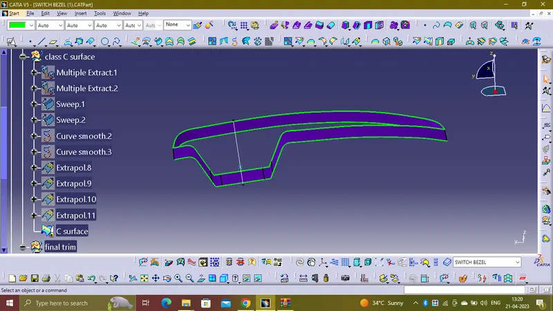
- A new geometrical set with the name C surface was created.
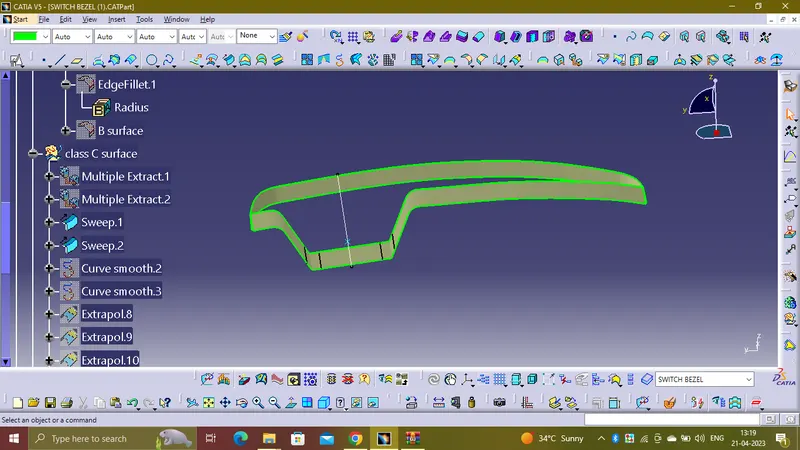
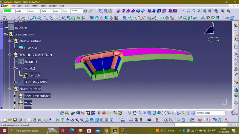
- Multi-extract command the boundary was created on the A and B surface.
- It was made into a surface by using swept option and the tooling axis was considered and also the draft angle=3degrees.
- The surface was having too many marks so smooth curve command selected and replaced by the the above curve to obtain a smooth surface without marks.
- Surface A and C were joined by giving 0.003mm as merging distance.
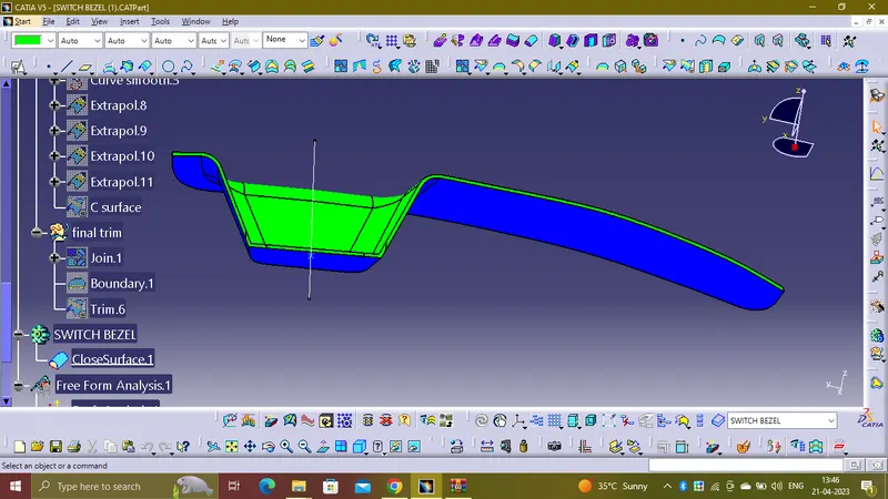
FINAL TRIM
- In final trim we have to join the class A surface with class C surface
- After that have to join with class B With joined surface
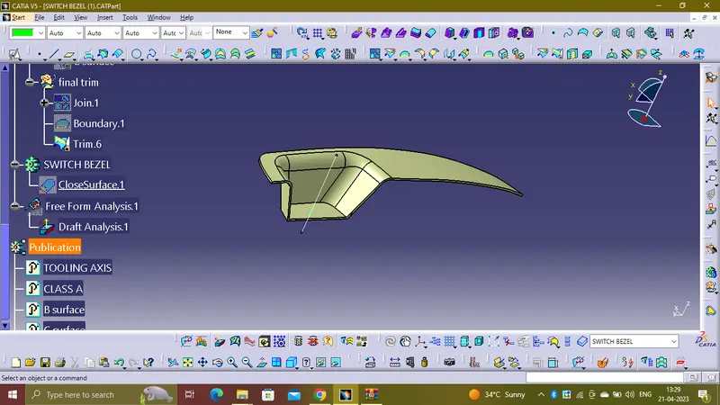
CLOSE SURFACE
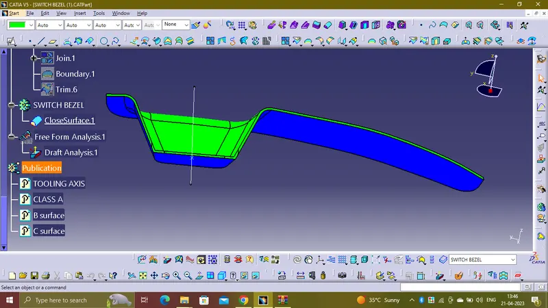
- The window was switched to part design where the hollow part was turned into a solid part by using closed surface command.
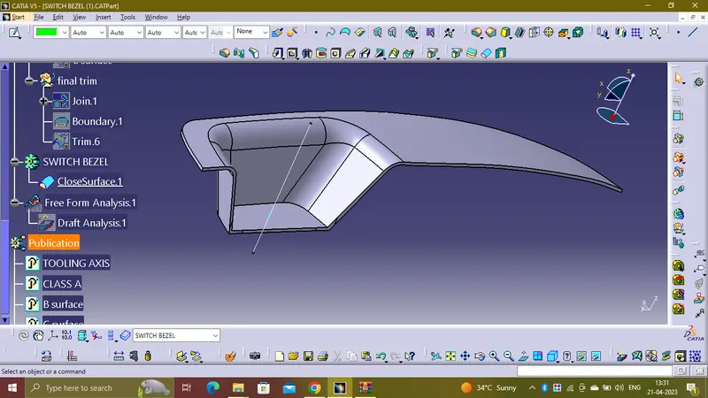
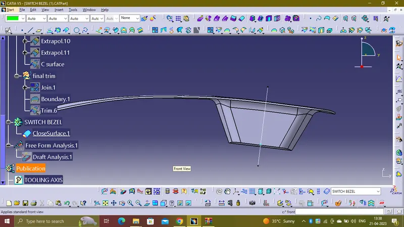
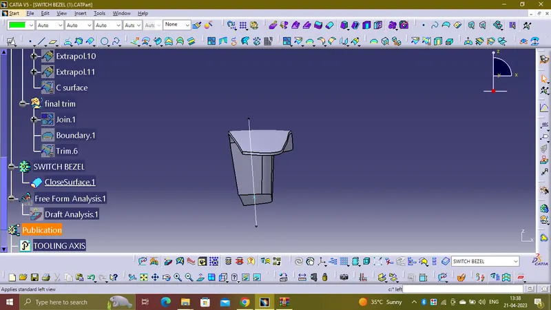
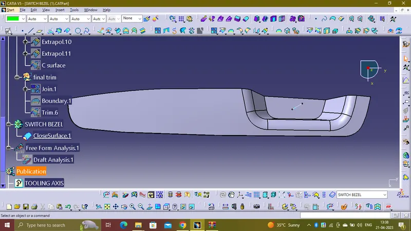
The same part is shown in different views below:
ISOMETRIC VIEW
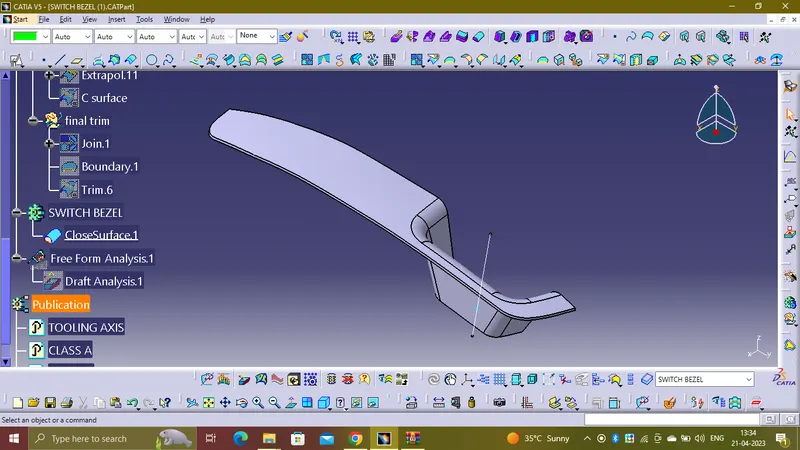
FRONT VIEW
SIDE VIEW
TOP VIEW
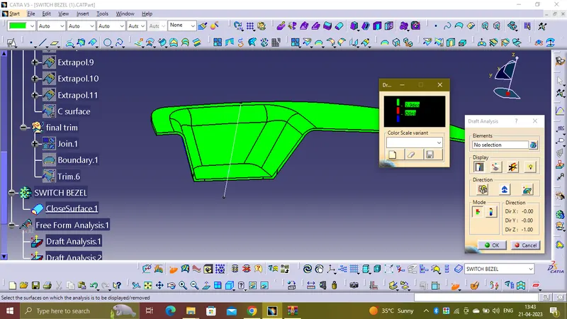
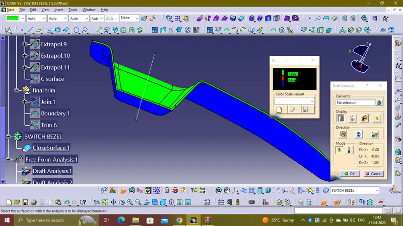
DRAFT ANALYSIS
- Draft analysis was carried out by switching to material view.
- The compass was relocated to the new position by aligning with the tooling axis and locked.
- By taking the pointer on the part which showed a red cross, a click on the same location gave the result.
- There were some region with less than 3degree value which was shown by red color.
- The value was changed to 2.9degree and the part turned into green which states that the part is toolable and produceable.
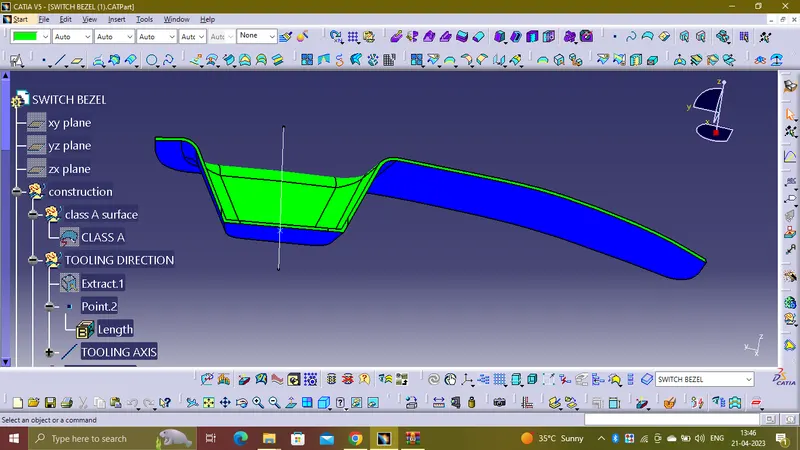
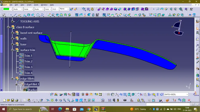
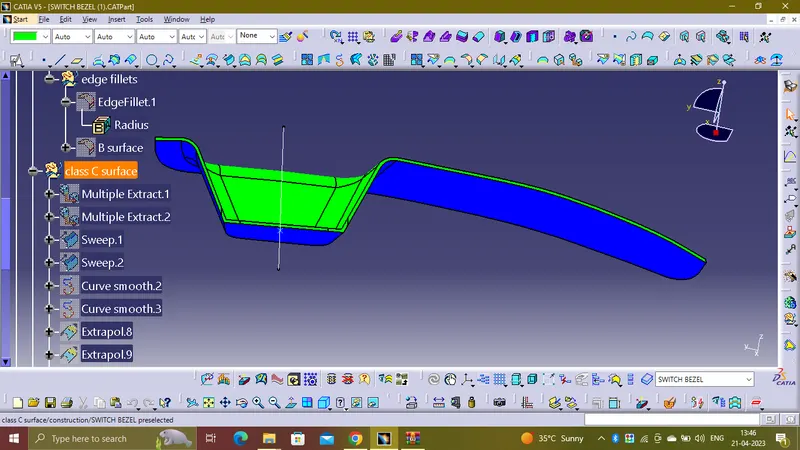
TREE STRACTURE
For more details cat file attached ....