Week 9-Challenge
Objective:
To create a connections for the given model using Hypermesh.
Description:
The following is the models which we need to do the connections.
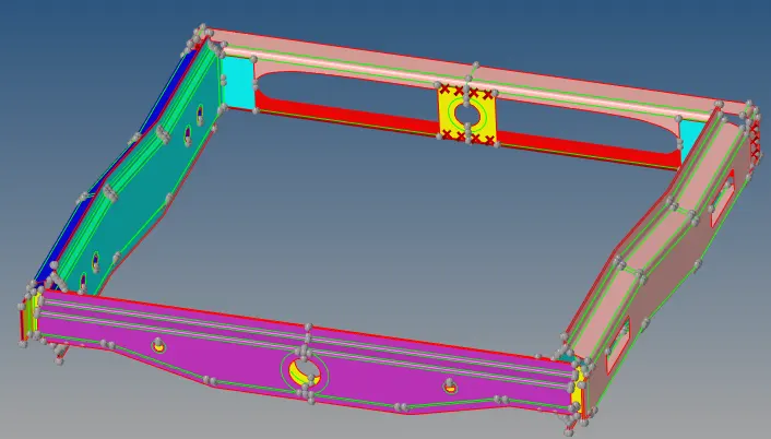
The following are the mesh element size need taken in to consideration for meshing the Geometry.
1. Target/Average length = 10
The following are the type of connections need to be done for the given model.
1. Right_Rail_2 & Front_truss_1:- Seam-Quad(angled+capped+L)
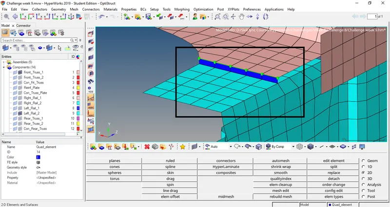
2. Left_Rail_2 & Front_truss_1:- Quad elements
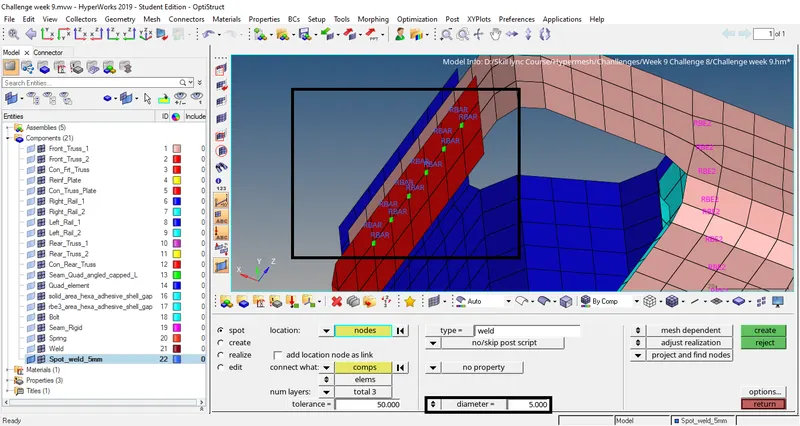
3. Front_truss_2, Front_truss_1 & Right_Rail_1:- Spot weld with 3 Layers and 5 mm Diameter
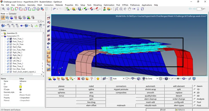
4. Front_truss_2, Front_truss_1 & Left_Rail_1:- Hexa (Adhesive)
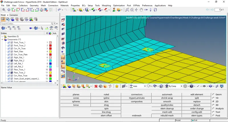
5. Rear_truss_2 & Right_Rail_2:- Bolt Connector
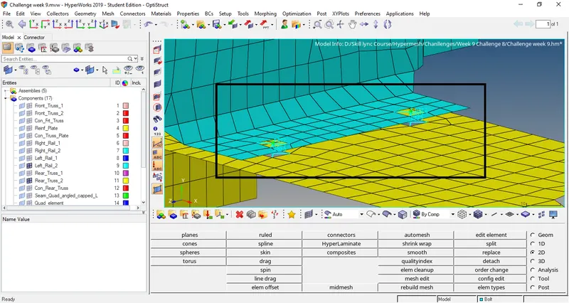
6. Rear_truss_2 & Left_Rail_2:- Bolt Connector
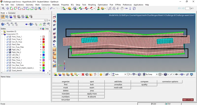
7. Right_Rail_1 & Right_Rail_2:- Spot-weld with Rigid Elements
8. Left_Rail_1 & Left_Rail_2:- Spot-weld with Spring Elements
9. Rest all the component left Join them with suitable connectors
Procedure:
A: Meshing:
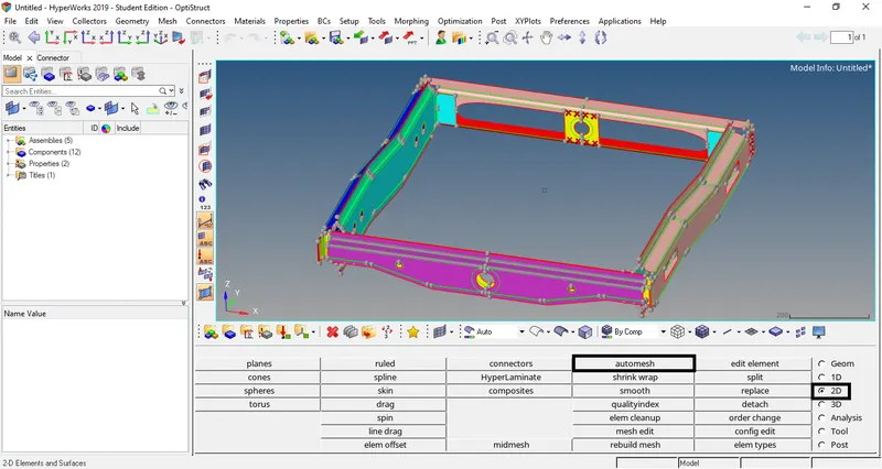
1. Now we can see that the model is not meshed so now we will do meshing. Now go to Automesh option under 2D.
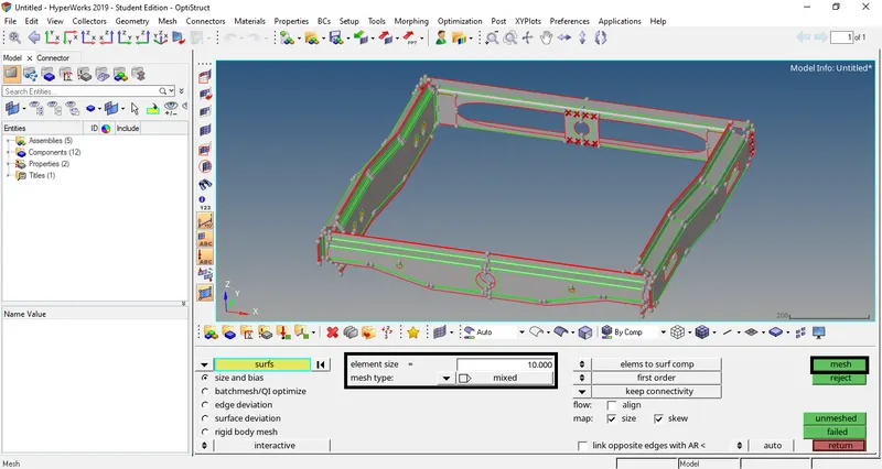
2. Now enter 10 in element size and select element type as mixed and press mesh.
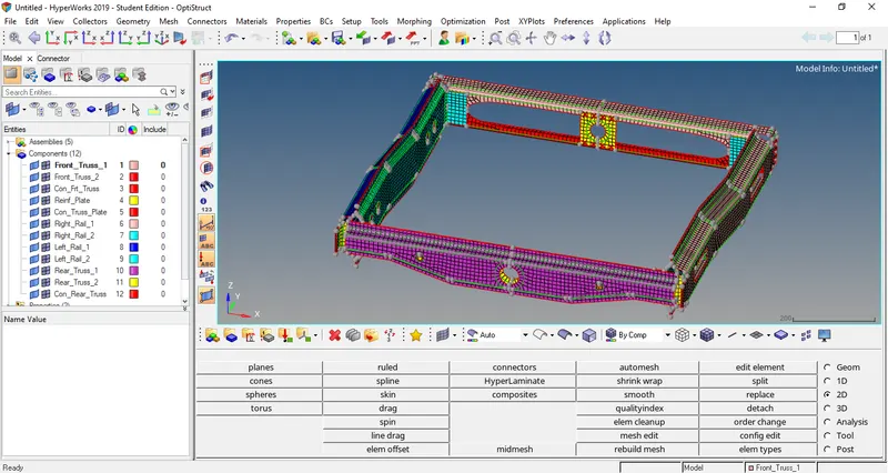
3. Now we can see the model is meshed.
B: Connections:
1. Right_Rail_2 & Front_truss_1 : Seam-Quad(angled+capped+L)
4. Now we will enable only above mentioned parts for connection.
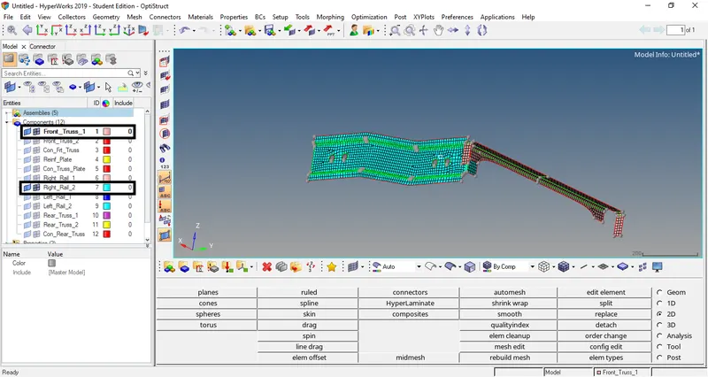
5. Now we will do the connection. As mention we need to connect this 2 component with Seam - Quad ( angled+capped+L ). So go to connectors under 2D.
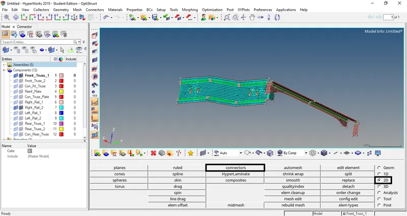
6. Select seam option.

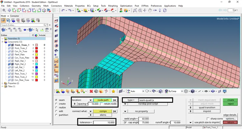
7. In seam option select location as node by path , spacing as 10 , Type as Seam - Quad ( angled+capped+L ) and in tolerence as 10.
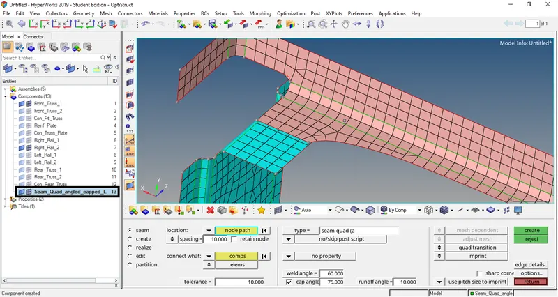
8. Now we will create a seperate component so that we can differentiate the connections in the model. Right click on model tab and select component and name as Seam - Quad ( angled+capped+L ).
9. Now select the nodes then press middle mouse button to confirm and select the component which needs to be connected and press create.
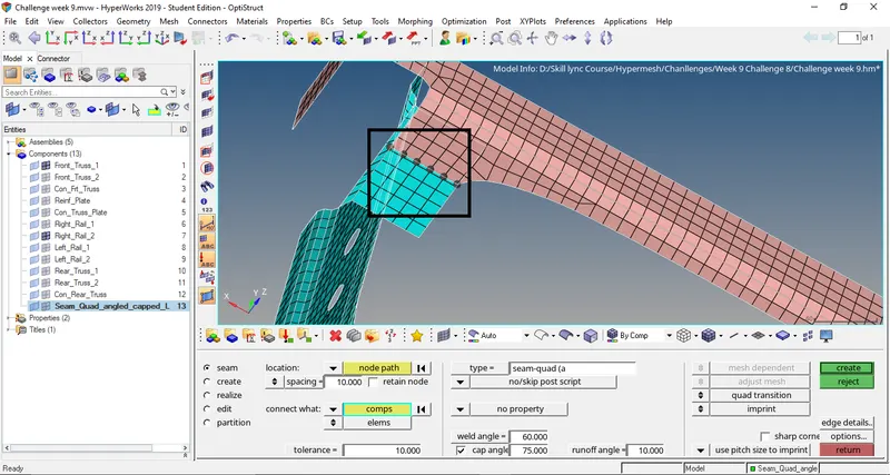
10. Now we can see the connection is done.
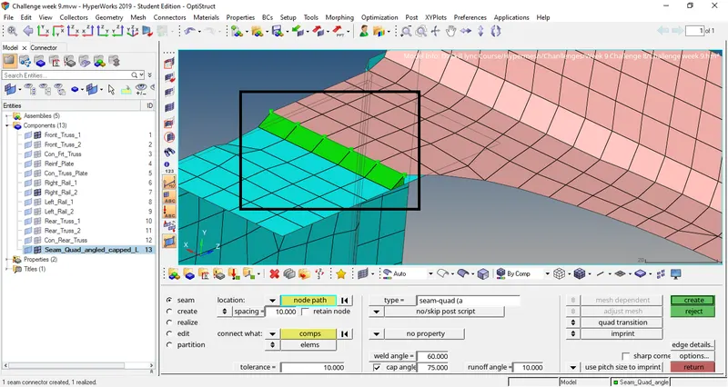
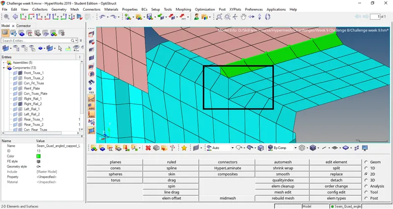
11. Now we can see the elements are not proper. Now we will fix the elements.
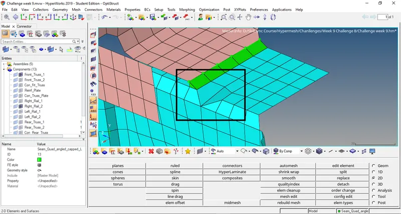
12. Now we will split the elements. Go edit element select split option and select one node other node now we can see the element is split.

13. Now we will translate the elements and make linear to the surface go Translate option under Tools and select the node which needs to translate and select the base nodes as shown and give the magnitude as 0.1. Then press Translate till it is linear to the surface.
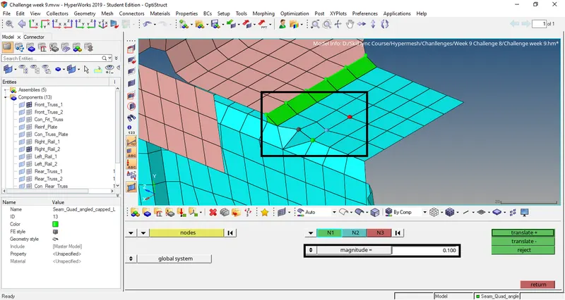
14. Now we can see the element is linear to the surface.
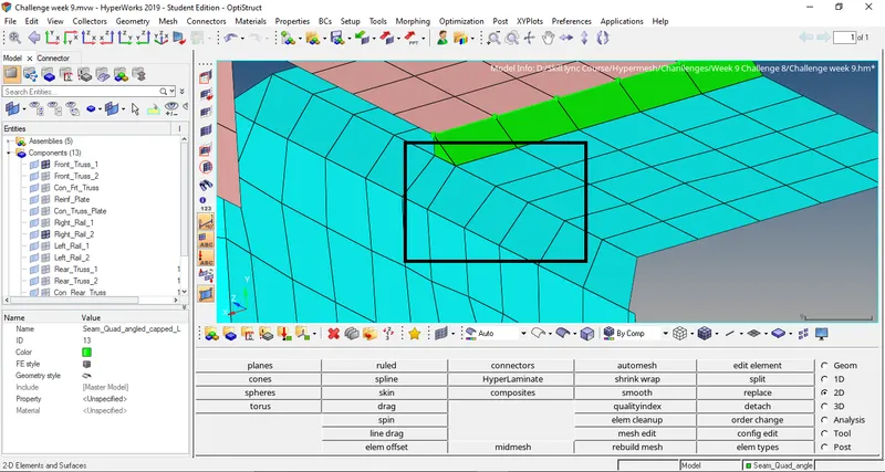
15. Now remesh the elements for proper mesh. Go to automesh option under 2D and select element and press mesh now we can see the elements are clean.
2. Left_Rail_2 & Front_truss_1 : Quad elements
16. Similarly follow step 4 to 15 for above mentioned parts of model. Select connector type as Quad. In Seam option.
3. Front_truss_2, Front_truss_1 & Right_Rail_1 : Spot weld with 3 Layers and 5 mm Diameter
17. Similarly follow step 4 to 15 for above mentioned parts of model. Select connector in that select weld option with diameter as 5mm and select nodes and select the 3 component and press create.
4. Front_truss_2, Front_truss_1 & Left_Rail_1 : Hexa (Adhesive)
18. Similarly follow step 4 to 15 for above mentioned parts of model. Select connector type as Adhesive. In Area option.
5. Rear_truss_2 & Right_Rail_2 : Bolt Connector
19. Similarly follow step 4 to 15 for above mentioned parts of model. Select connector type as Bolt( General ) and select Create hole, If none . In Bolt option.
6. Rear_truss_2 & Left_Rail_2 : Bolt Connector
20. Similarly follow step 4 to 15 for above mentioned parts of model. Select connector type as Bolt( General ) and select Create hole, If none . In Bolt option.
7. Right_Rail_1 & Right_Rail_2 : Spot-weld with Rigid Elements
21. Similarly follow step 4 to 15 for above mentioned parts of model. Select connector type as Rigid. In Seam option.
8. Left_Rail_1 & Left_Rail_2 : Spot-weld with Spring Elements
22.Similarly follow step 4 to 15 for above mentioned parts of model. Select connector type as Spring. In Seam option.
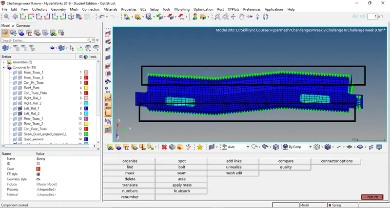
9. Rest all the component left Join them with suitable connectors
23. Using connector options we will connect other part of the model with suitable connectors.
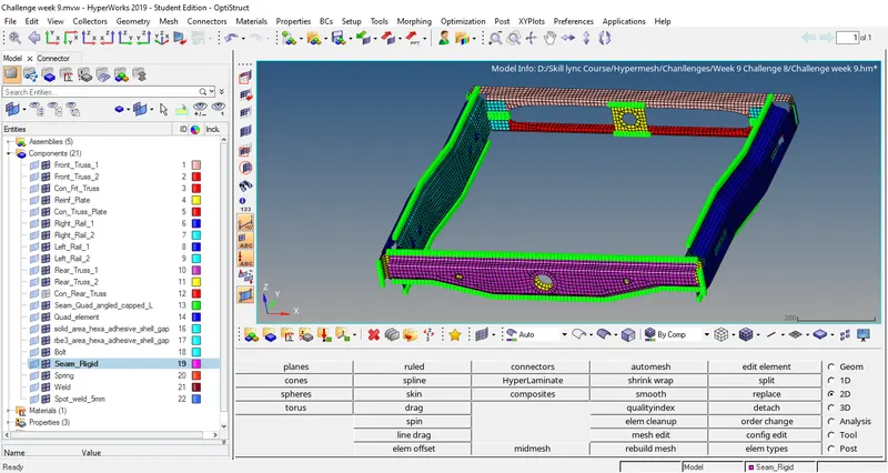
C : Conclusion:
Completed the Connection for all the areas.
D: Learning Outcome:
1. Learnt how to connect the models.
2. Learnt how many types of connections available in the industries usage.