Week 9 - Challenge 1 - Base Bracket Design
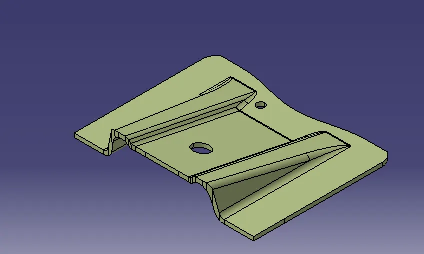
AIM: Create the Base Bracket Plastic part using the provided Class-A surface. In order to complete the draft analysis on the model, the tooling axis for the specified Class A Surface must first be built in accordance with the draft angle specifications.
Class A:is the surface that is created by the concept sketches made by free hand sketchers. The finalised sketch is then fed to the computer and a 2D surface is created out of it by the use of a software like Alias. This computerized design is known as Class A surface.
Class B: Class B surface is generally called the engineering surface where all the ribs and fixation points present.
Class C: is again a reference surface that is created by the design engineer to connect Class A and Class B surface also known as the side wall of the surface.
Step Involed in Tooling Axis:
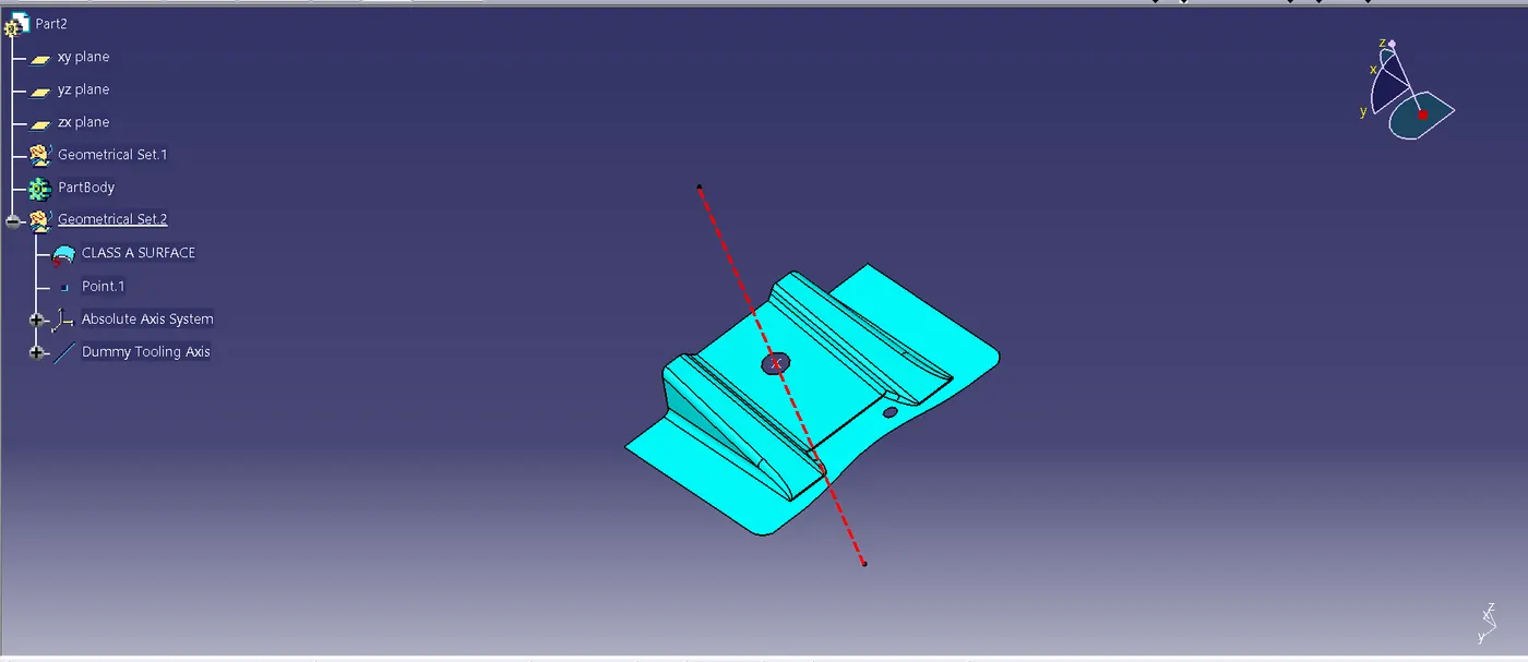
- First of all, check Surface A connectivity
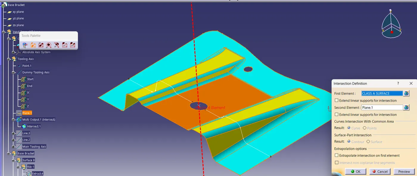
- Create Dummy tooling Axis and YZ Plane using point
-
Then two slopes on either side of the intersection was used to create two more lines and in the end a bisector line was created which became the main tooling axis.
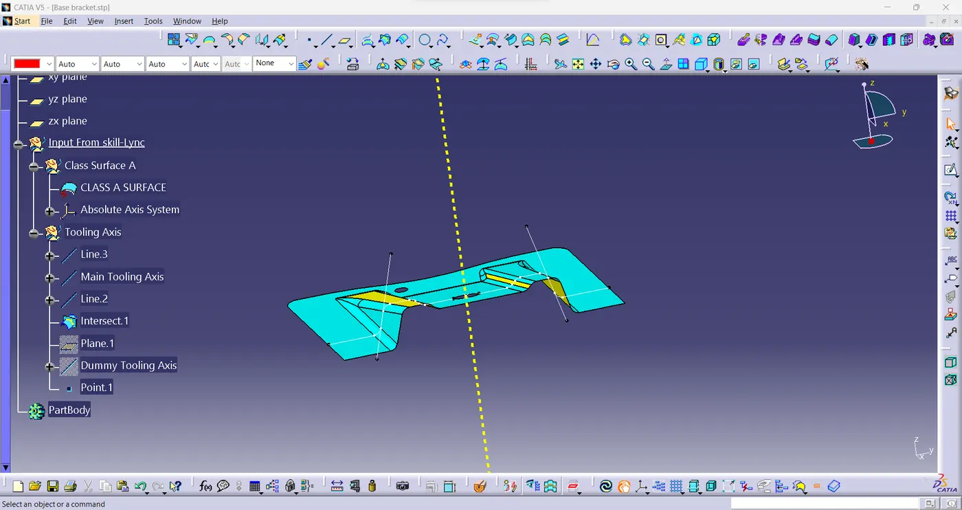
- Draft analysis:
1.Open Featured Draft Analysis tool in the tools.
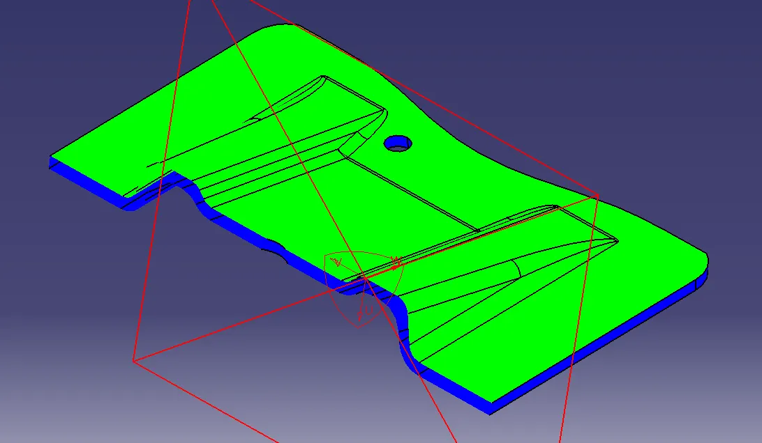
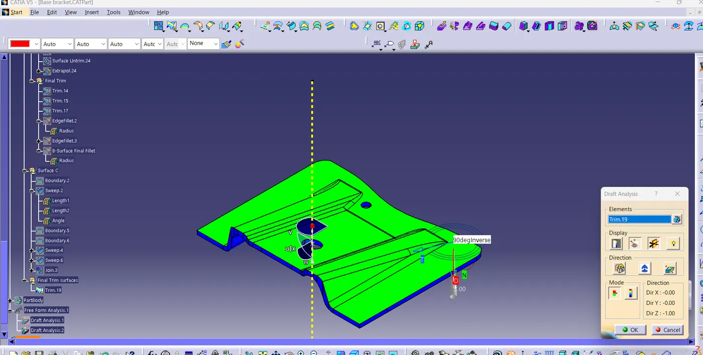
2. 3 degree is Nominal value for Plastic Design using Draft Analysis
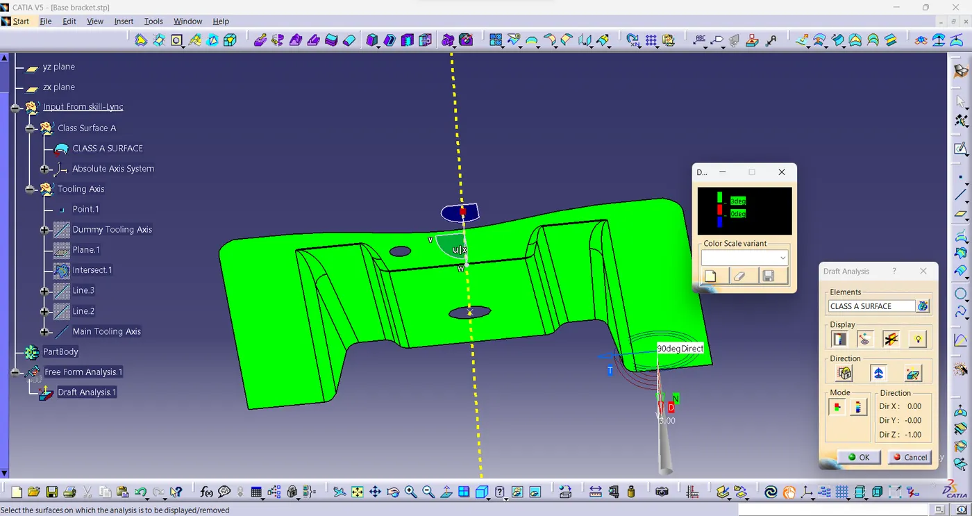
- The green region shows the part which is toolable or produceable by the molding machine and the draft angle is 3degree.
- Blue color region states that the part can be allowed in some OEMs but still need to be improved for the other OEMs as the draft angle is more than 3 degrees.
- Red color which is not there in this case states that the draft angle is less than 3 degree and cannot be produced or if produced would be faulty.
B-Surface:It's also Called as Engineering Surface
- Extract Surface from class A
- Unfrim the Extract surface and Extrapol
- Trim the Extrapol surface and Offset the Surface Thincknees=2.5mm
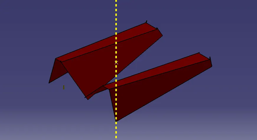
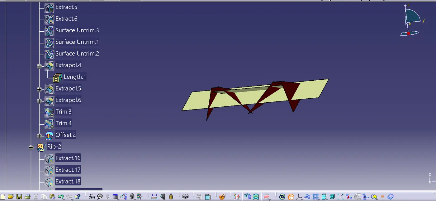
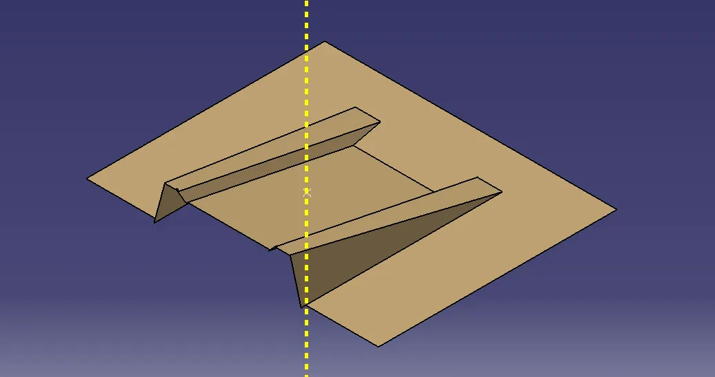
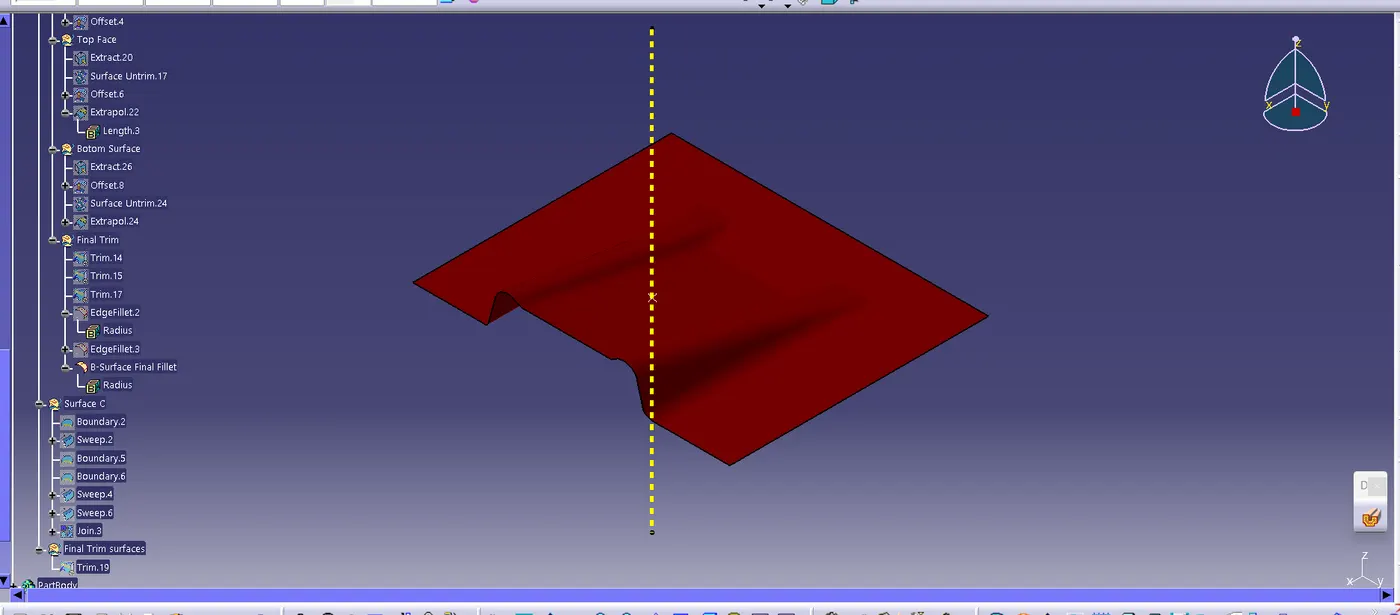
- Edge Fillet the B-surface using radius 2.5+3=5mm
.
Surface C:
- Create Boundary Definition using Surface A.
- Sweep the Boundary with Darft direction on 3 degree angle.
- using join command to Join A-surface and C-surface
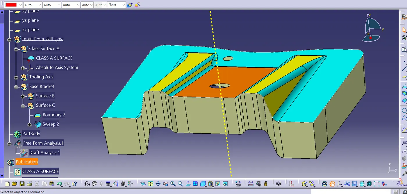
- Trim the C-surface With B-surface.
- Featured Draft Analysis for final Surface
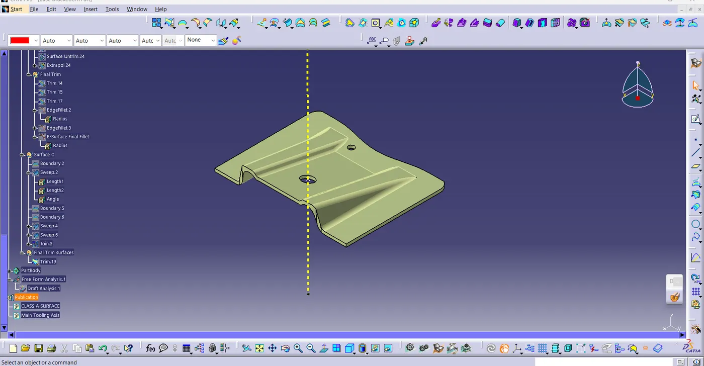
Close surface:
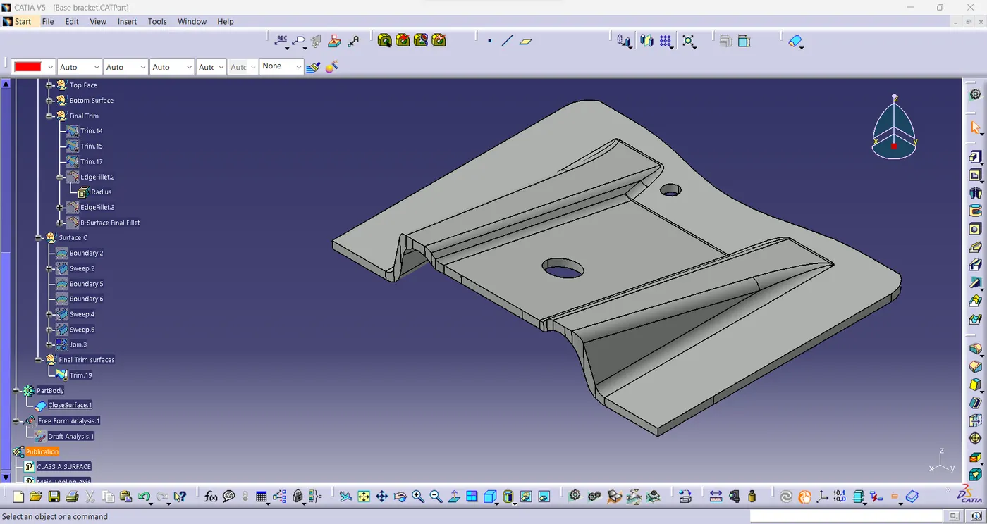
- Create Solid body using Close Surface command.
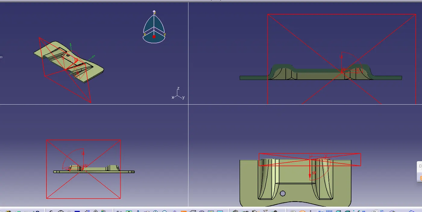
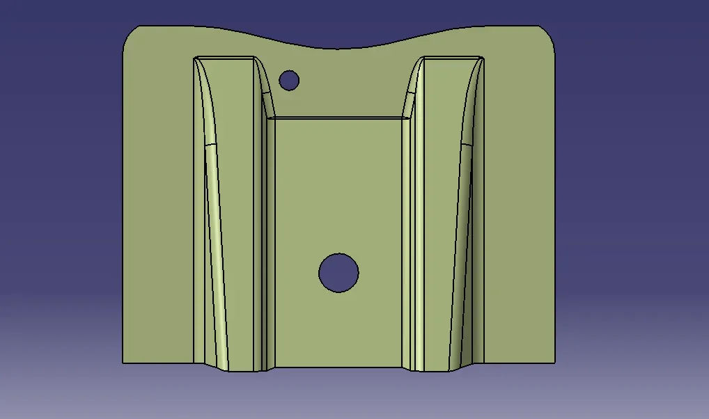
Top view:
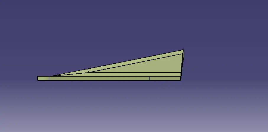
Side View:
Isometric View