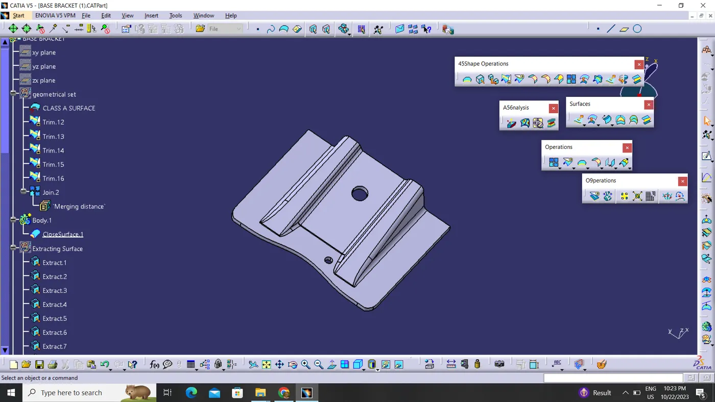
Week 9 - Challenge 1 - Base Bracket Design
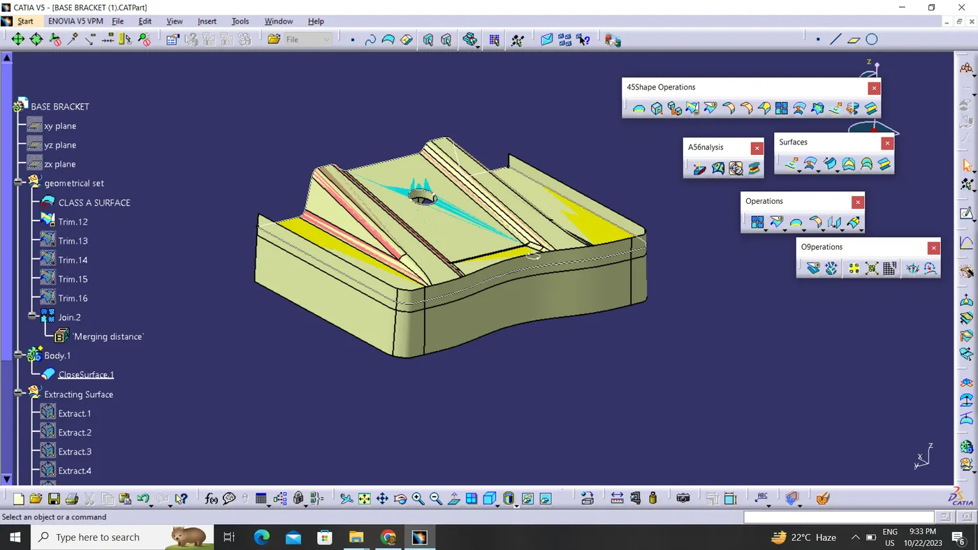
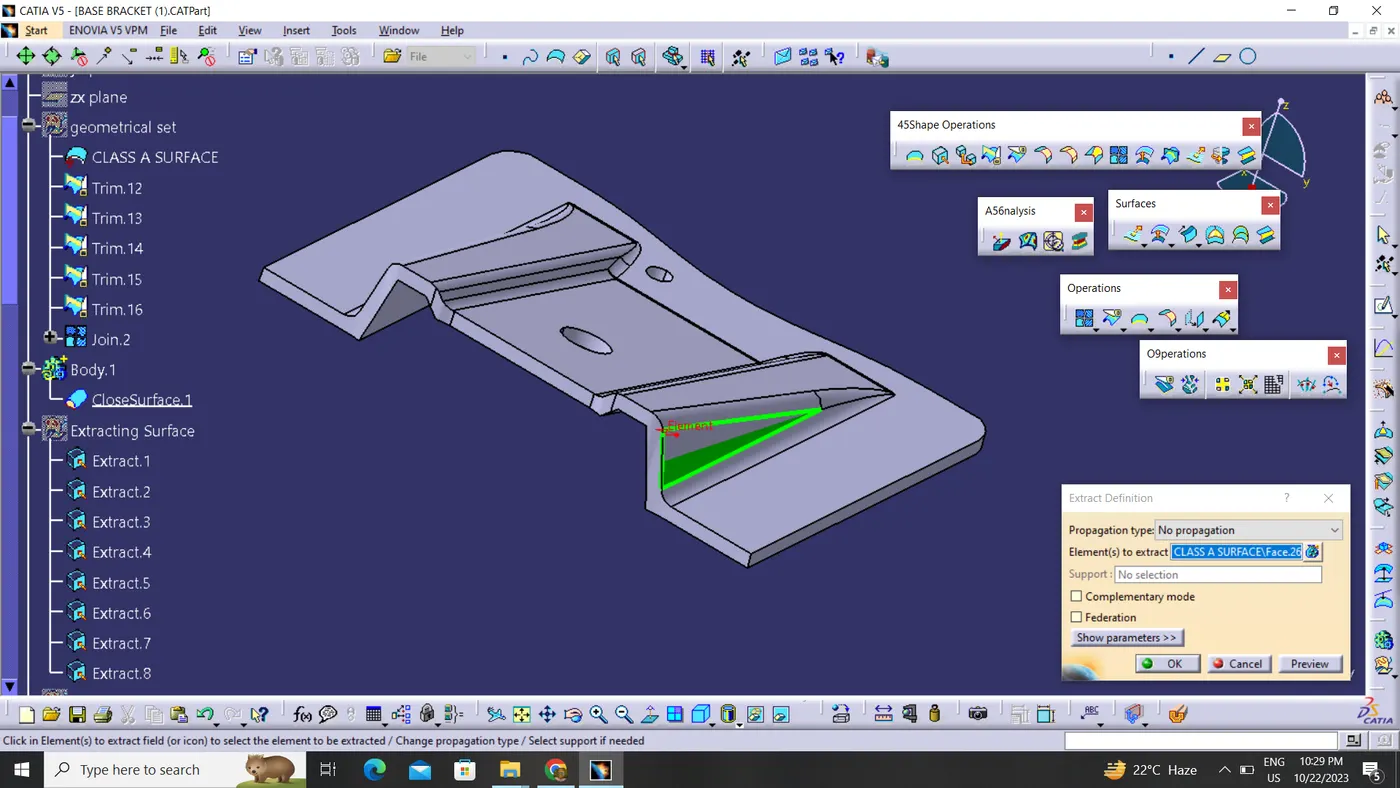
Creation of a part from the given Class A surface is done by creating 2 surfaces that are B surface and C surface.
Class A is the surface that is created by the concept sketches made by free hand sketchers. The finalised sketch is then fed to the computer and a 2D surface is created out of it by the use of a software like Alias. This computerized design is known as Class A surface.
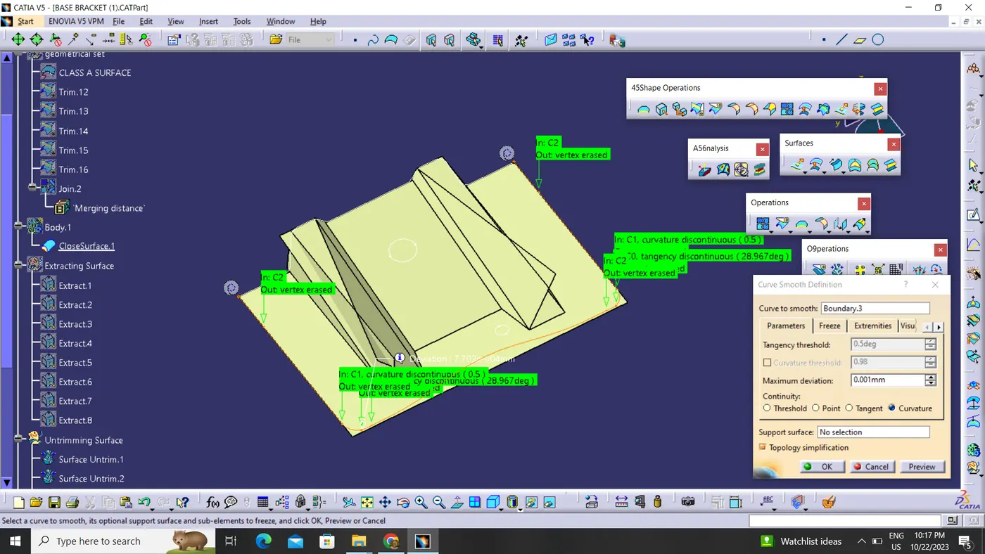
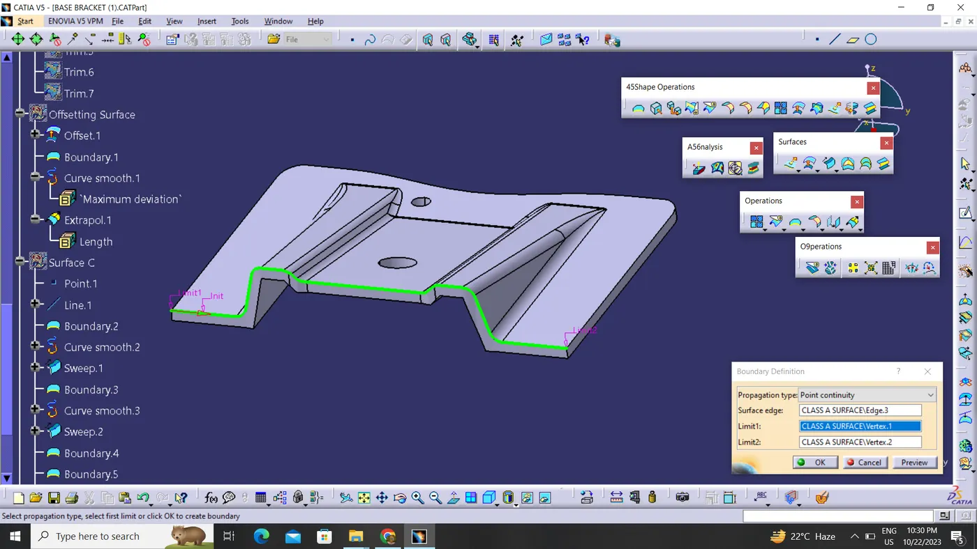
Class B is a reference surface that is created by the design engineer and is a copy of the class A surface that is at a distance equal to the thickness of the part.
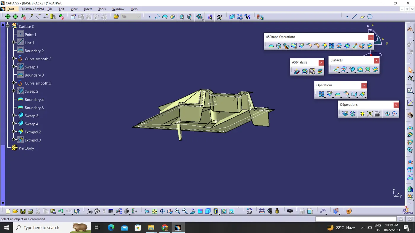
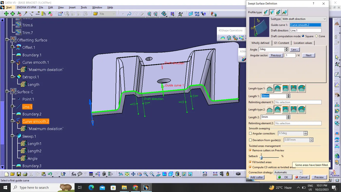
Class C is again a reference surface that is created by the design engineer to connect Class A and Class B surface also known as the side wall of the surface.
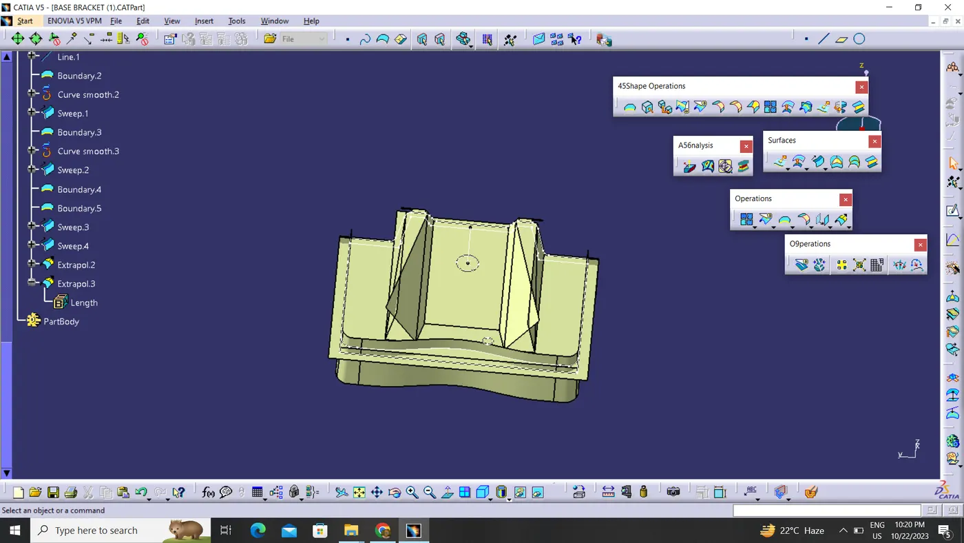
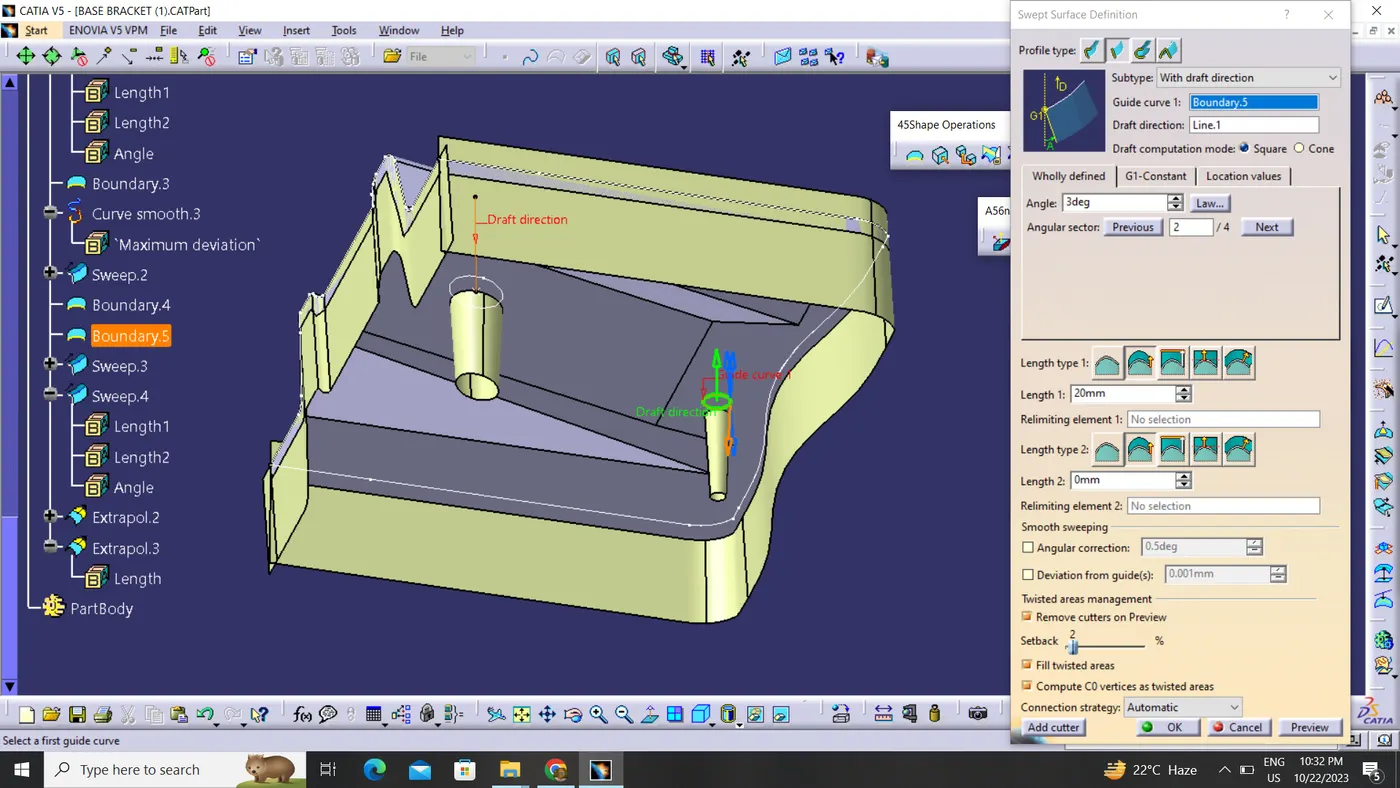
The technique that is used to create the model is to initially create a class B surface at a distance equal to thickness(2.5mm here) and later a vertical surface class C. Then trim the three surfaces to obtain the required part.
->) Steps involved in the creation of the aforementioned part
*) The first task to begin the model with was to create the tooling axis. The model was observed from all the 3 planes and xy plane was selected to create the part and so the hole was taken into consideration and a point was created.
*) The same point was taken as reference and a dummy tooling line was created. This line was later used to create a plane to obtain the intersection pattern.
*) The two slopes on either side of the intersection was used to create two more lines and in the end a bisector line was created which became the main tooling axis.