Week 9 - Challenge 1 - Base Bracket Design
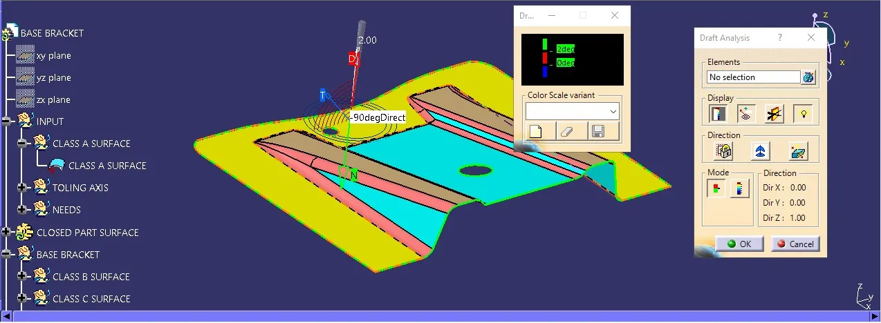
IMAGE OF COMPLETE DRAFT ANALYSIS
1.
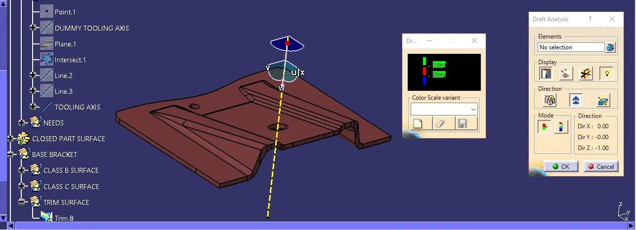
2. IMAGE OF THE COLOR SCALE VARIANT
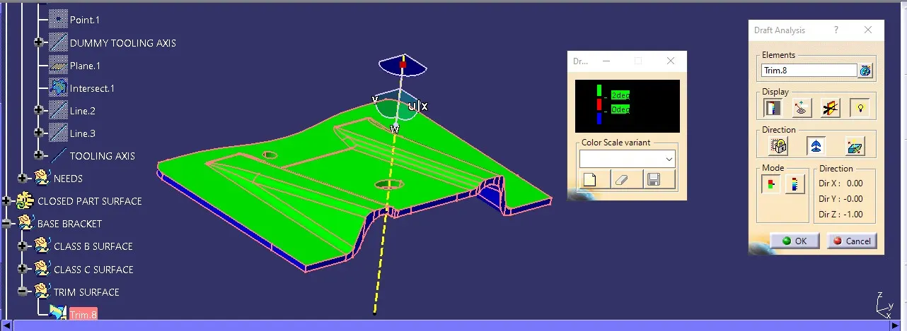
IMAGE IN A SURFACE MATERIAL
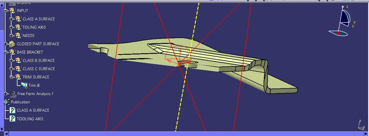
IMAGE OF A SOLID PART MATERIAL
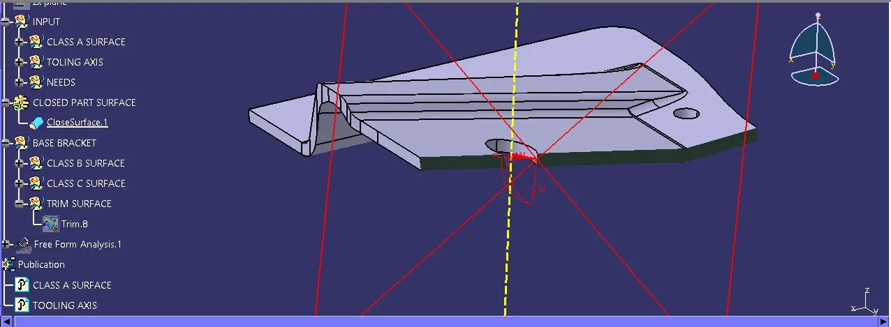
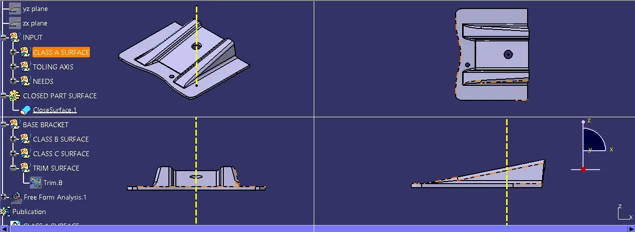
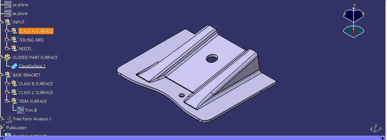
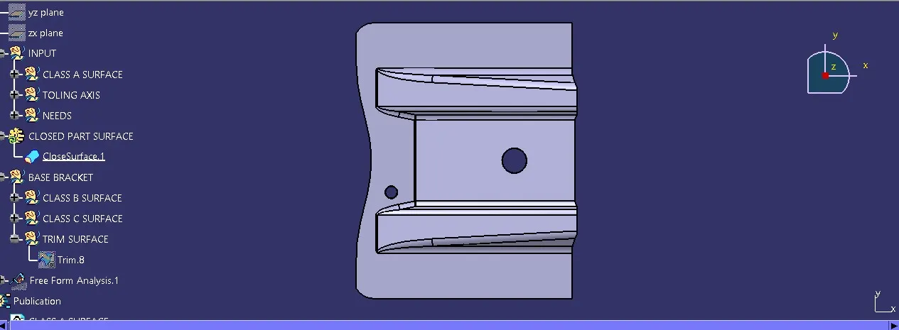
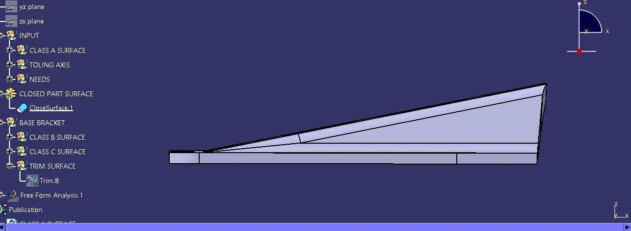
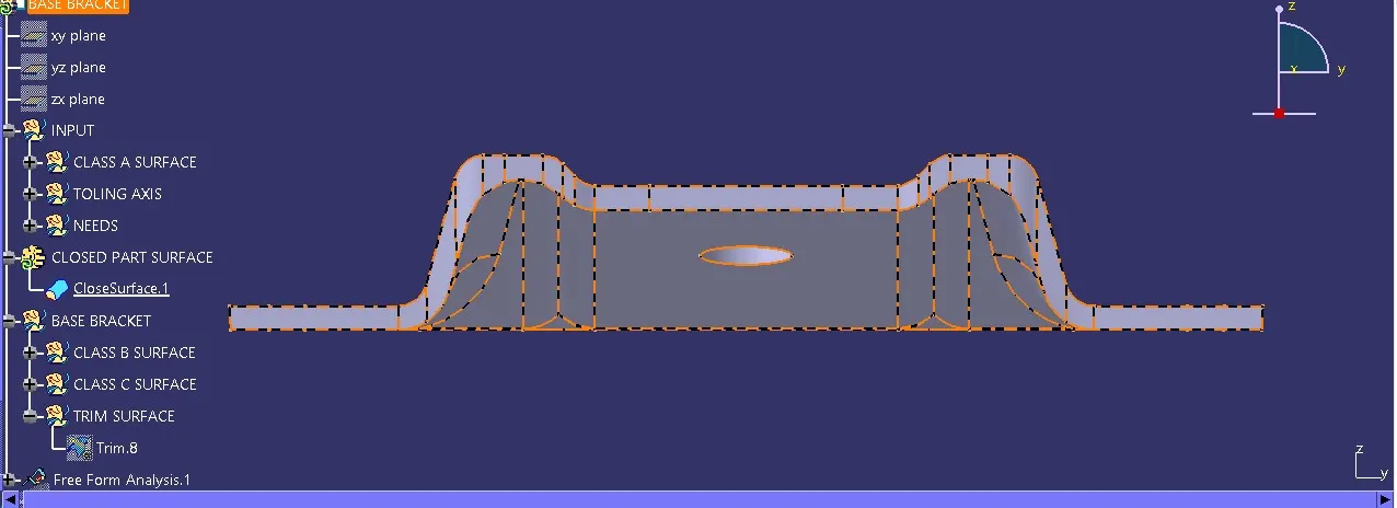
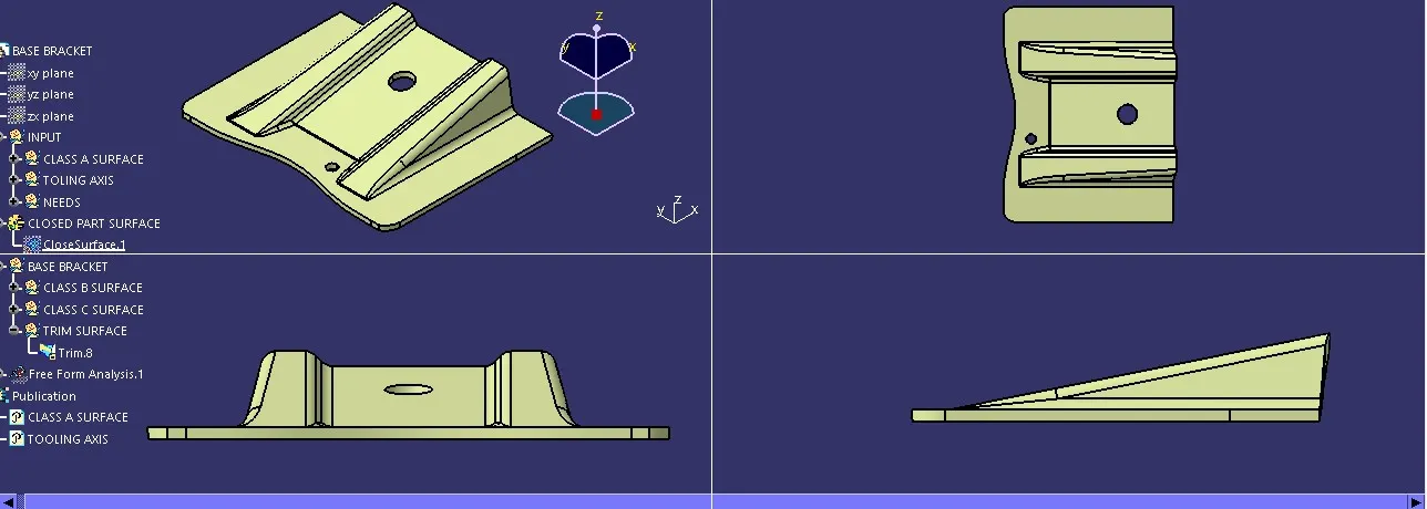
REPORT SUBMISSION FOR DRAFT ANALYSIS AND TOOL AXIS CREATION
Draft analysis is a tool that is used to determine whether a part model can be easily removed from the mold or die during manufacturing. A sufficient draft angle is required to ensure that the part can be ejected without damage. The draft angle is the angle between the part surface and the direction of ejection. The minimum draft angle required will vary depending on the material and the manufacturing process. It is always best to consult with a manufacturing engineer to determine the specific requirements for wer part.
Color variation method in draft analysis
The draft analysis will display a color gradient on the part model. The areas with a green color have a sufficient draft angle and can be easily removed from the mold or die. The areas with a red color have a draft angle that is too low and may not be able to be removed from the mold or die without damage. The areas with a yellow color have a draft angle that is borderline and may require some additional machining to ensure that they can be removed from the mold or die.
Results:
-
- The draft analysis will display a color gradient on the part model. The areas with a green color have a sufficient draft angle and can be easily removed from the mold or die.
- The areas with a red color have a draft angle that is too low and may not be able to be removed from the mold or die without damage.
- The areas with a yellow color have a draft angle that is borderline and may require some additional machining to ensure that they can be removed from the mold or die.
Tooling axis creation is the process of creating an axis that represents the direction in which the mold or die will open. The tooling axis is used to perform draft analysis and to create other features, such as parting lines. The tooling axis is an important part of the design process for plastic parts. It is the direction in which the mold or die will open, and it is used to perform draft analysis and to create other features, such as parting lines.
One common method is to use the Bisect command. To do this, we would first need to create a plane that passes through the center of the part. Then, we can select two points on the part that are on opposite sides of the plane. Finally, we can use the Bisect command to create a line that bisects the distance between the two points. The line that we created is the tooling axis.
REPORT FOR THE WAY OF CREATING THE TOOLING AXIS, PARTICULARLY THE BISECTING METHOD
The bisecting method is a simple and effective way to create a tooling axis that passes through the center of a part and is perpendicular to its major surfaces. To use this method, we will need to:
- Create a plane that passes through the center of the part.
- Select two points on the part that are on opposite sides of the plane.
- Use the Bisect command to create a line that bisects the distance between the two points.
- The line that we created is the tooling axis.
We can use this axis to perform draft analysis or to create other features, such as parting lines.
- The plane that we use to create the tooling axis should be perpendicular to the major surfaces of the part. This will ensure that the tooling axis is also perpendicular to the major surfaces.
- The points that we select to bisect the distance between should be on opposite sides of the plane. This will ensure that the tooling axis passes through the center of the part.
- we can also use the Length constraint to ensure that the tooling axis is the desired length.
The best method for creating a tooling axis will depend on the specific part and the manufacturing process that will be used. However, the bisecting method is a simple and effective way to create a tooling axis that is perpendicular to the major surfaces of the part.