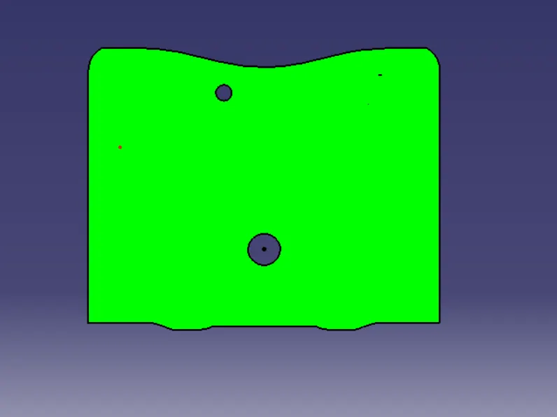
Week 9 - Challenge 1 - Base Bracket Design
Tooling Axis:
Tooling axis is created in a model to check whether the model done in software can be manufactured without any error while in live manufacturing process.
Steps involved in creating tooling axis:
- Need to check whether the provided surface is having full connectivity.
- Check about the X, Y and Z axis of the surface on which axis the part can be manufactured with less toolings.
- Once axis is fixed we need to create a intersecting geometry for the surface about that axis.
- Generally the perpendicular features to the tooling axis can be achieved, one need to have a look about the parallel features.
- Thus it can be checked by the draft analysis feature.
- For draft analysis one need to have a bisecting line which will be considered as the tooling axis of the surface.
- The bisecting line should be taken in consideration of all axis apart from the tooling direction.
- Once the angle is achived in draft analysis, one can be confident that the part can be manufactured with less tooling and errors.
- Generally the minimum draft anglle followed all over the industries is about 3 degree.
- Thus by draft analysis one can confirm whether the proposed model is feasibile for live manufacturing or not.
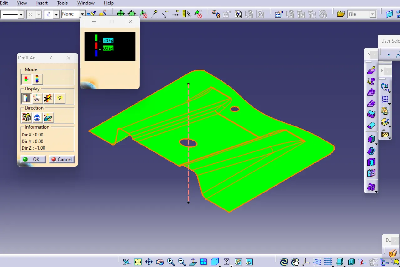
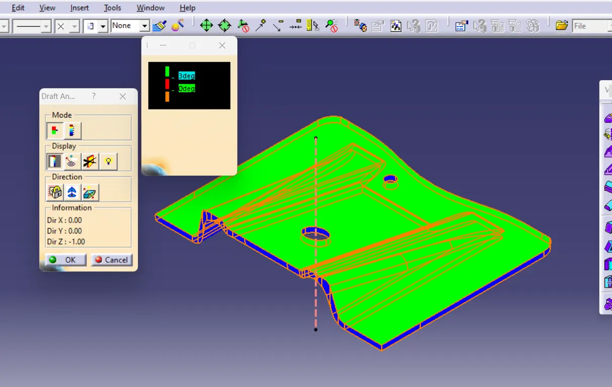
Below images are the Draft analysis of the Class A surface and the Solid Model
Class A surface :
Solid Model:
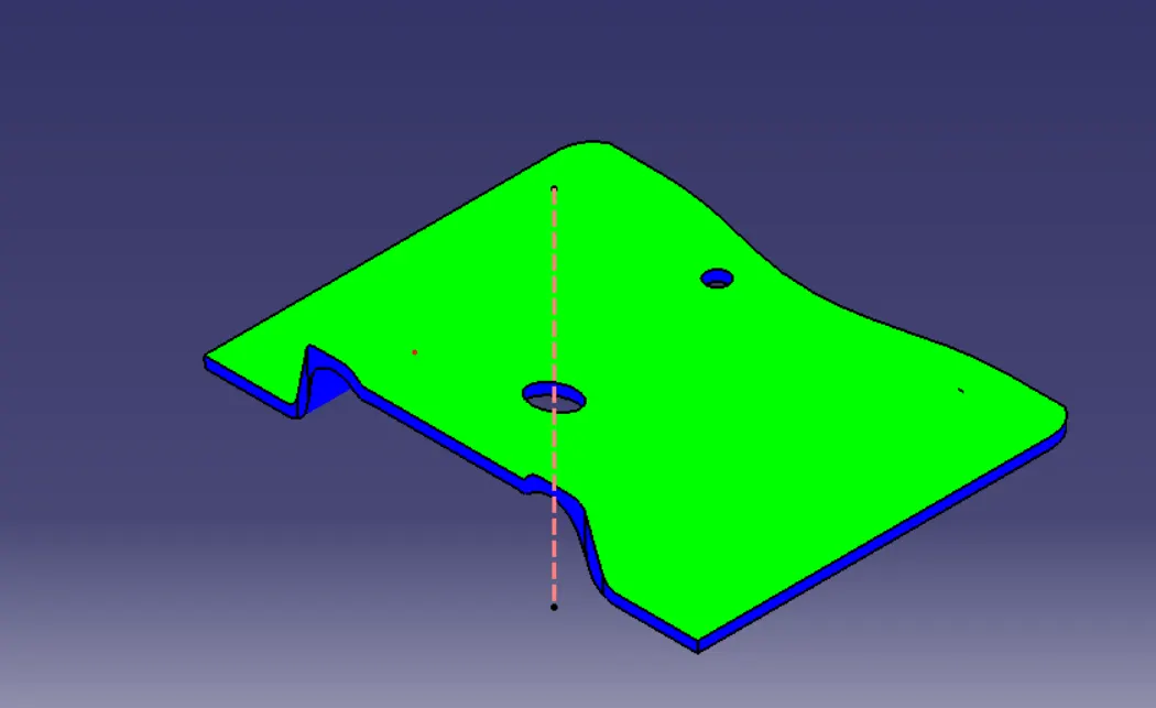
Different views of solid model with draft analysis:
Isometric View:
Front View:
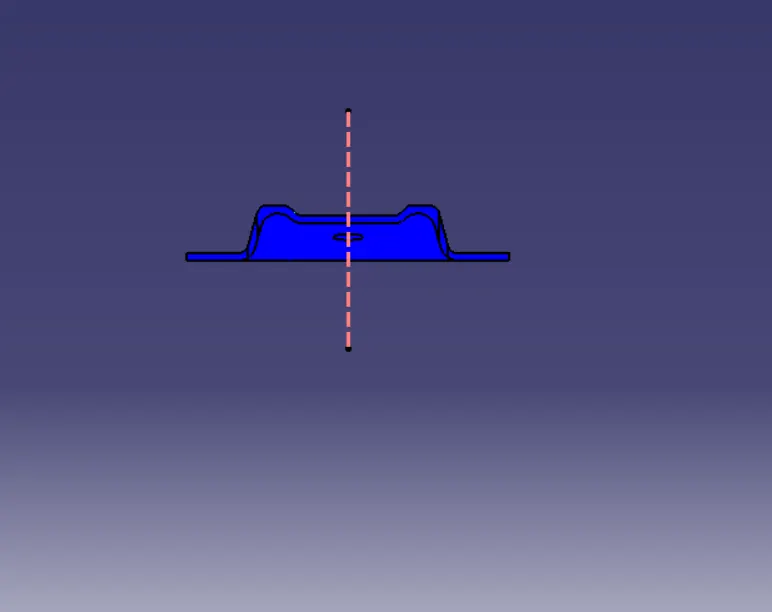
Side View:
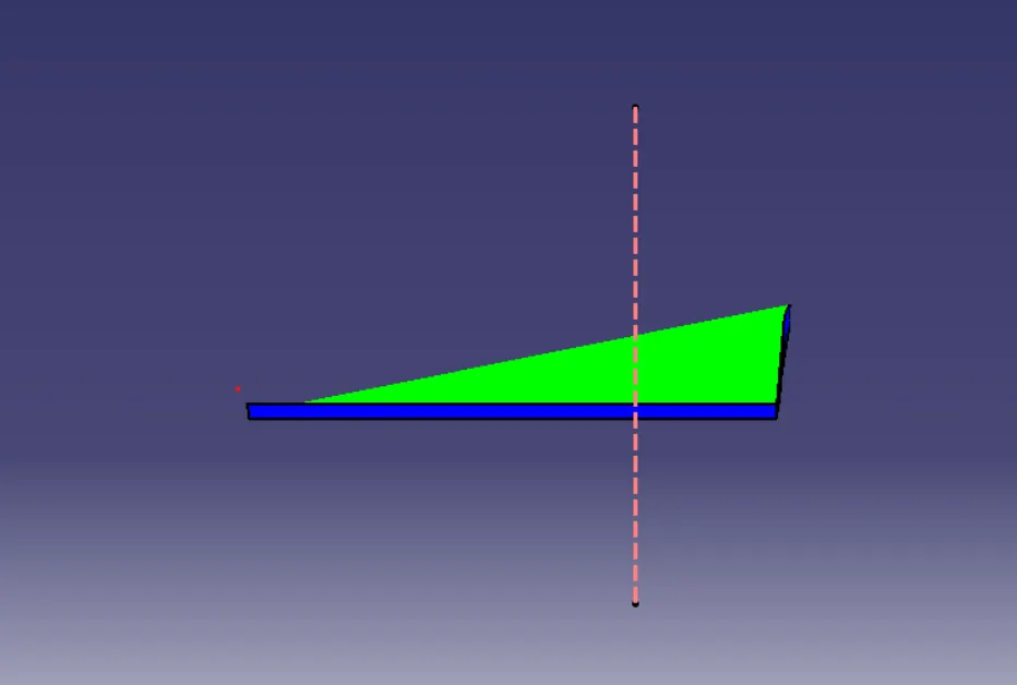
Top View: