Week 9 - Challenge 1 - Base Bracket Design
BASE BRACKET PLASTIC COMPONENT DESIGN
Aim :- To design the Base Bracket plastic component through the given Class-A surface.
Objective :-
- To create a proper tooling direction.
- To perform draft analysis of the plastic component.
- To design the base bracket plastic component by creating the B-Surface and C-Surface using the given Class-A surface.
Introduction :-
CLASS-A SURFACE : A surface made by the designer which is given as an input to the plastic modeler to work on. It is aesthetic surface and the outer most surface.
CLASS-B SURFACE : A surface below a certain thickness from the class-A surface is class-B surface. This is the surface that contains engineering aspects of a model.
CLASS-C SURFACE : A surface that joins class-A and class-B surfaces is class-C surface.
Methodology :-
In this model we have focused on the following things:-
- Tooling axis.
- Draft analysis.
- Class-B surface.
- Class-C surface.
- Making a solid model from surface.
Following tools were used to reach the final step:-
- Extract.
- Un-trim.
- Trim.
- Extrapolate.
- Offset.
- Edge fillet.
- Boundary.
- Sweep.
- Joint.
- Close Surface (part design).
Tooling Direction :-
Tooling axis is the direction in which mold or core and cavity opens. The ejection of the part from mold depends on the draft. A zero draft can result in difficult or no ejection due to shrinkage. It is recommended to add a minimum of 0.5 to 1 degree upto 3 degree of the draft for non-textured surface & 3 to 5 degree of draft for textured surfaces.
Procedure to create the tooling axis using bisecting method :-
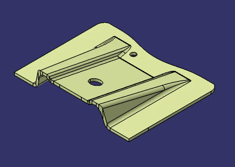
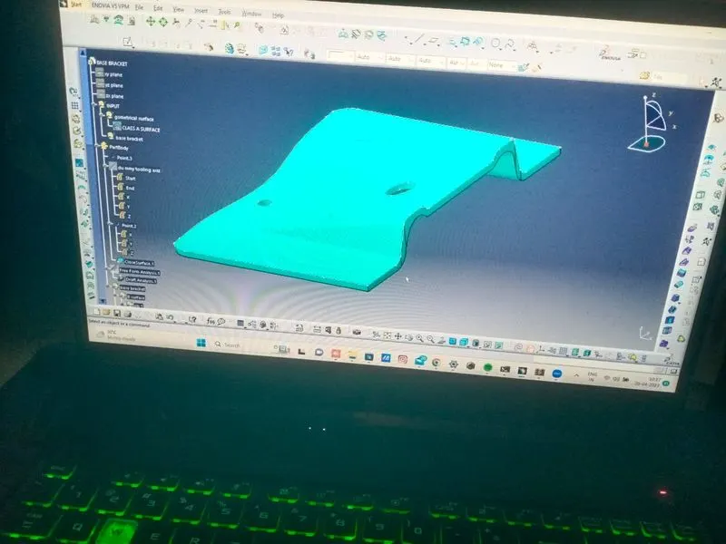
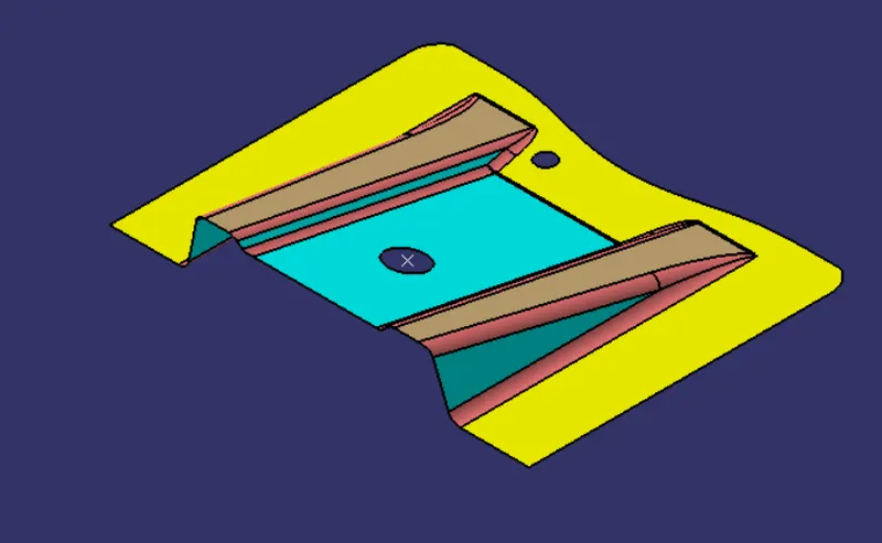
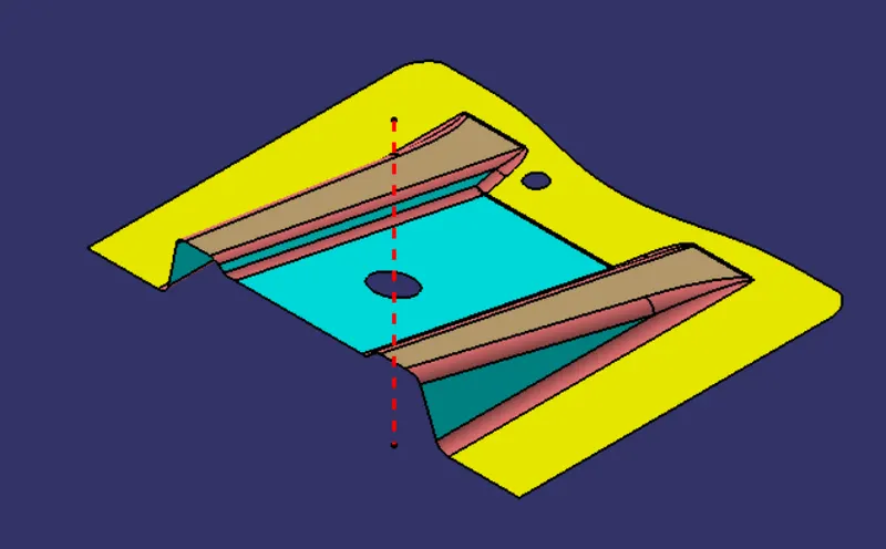
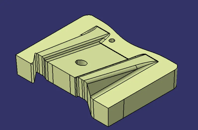
following Class A surface is provided to design the base bracket plastic component.
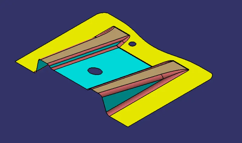
Point is created at the centre of a hole.
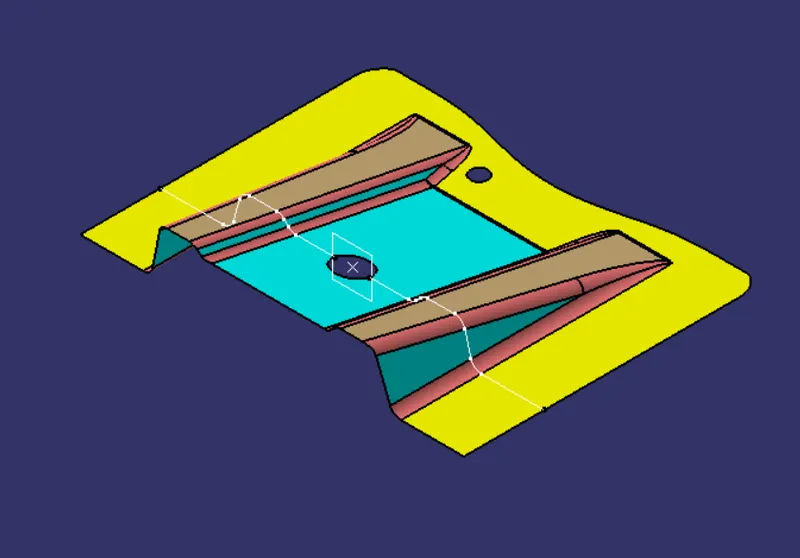
YZ Plane is created at the center of the hole and intersection of a surface is taken along the created plane.
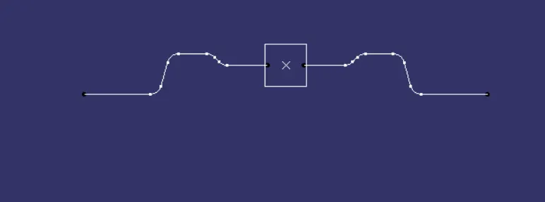
Lines are drawn to the side faces of the intersected curves then bisecting line is created between these two lines.
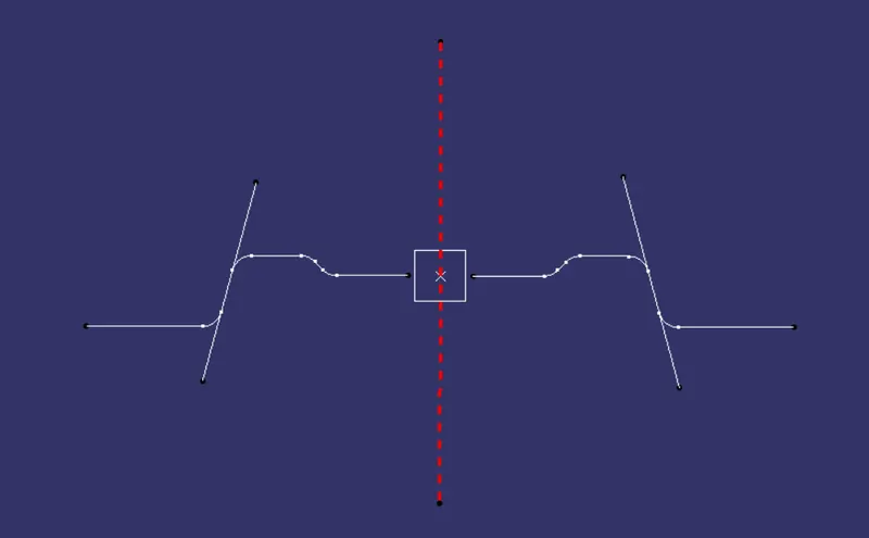
In this way we can create the tooling direction.
Draft analysis :-
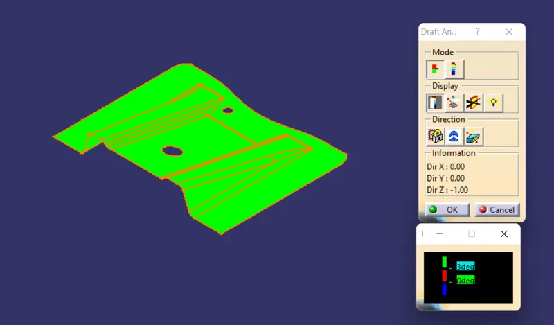
Draft analysis is performed based on color ranges identifying zones on the analyzed element where the deviation from the draft direction at any point, corresponds to specified values. Minimum draft angle is considered as 3 degree.
Class A-Surface :-
Class B-Surface :-
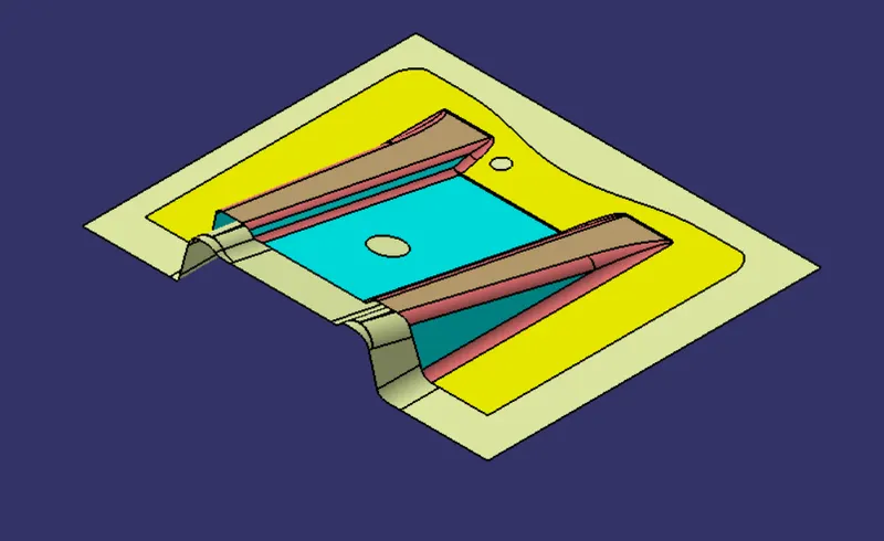
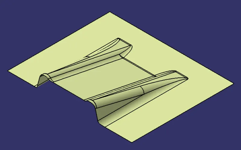
Class B-Surface is extracted from the A-surface and it is offseted at 2.5mm in downward direction.
Class C-Surface :-
C-Surface connects the class A-Surface and B-Surface. It is created using Sweep command. Boundry of the class A-Surface is swept along the tooling direction.
Final Part :-
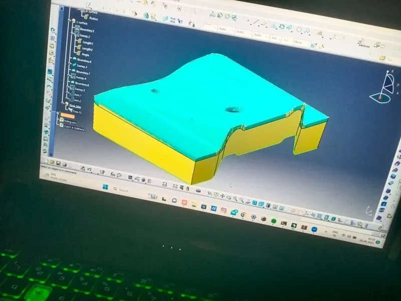
A & C-Surface are joined together then it is trimmed along the B-Surface.