Week 9 - Attachment Feature Creation (Ribs & Screw Boss) - Challenge 1
Design of Ribs & Screw Boss On Door Handle
Objective-: We have to Create close Surface from given classs A Surface and create attachment feature Ribs & Screw Boss On it.
Step1. Tooling Axis Creation:
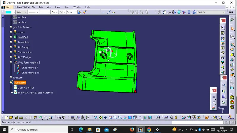
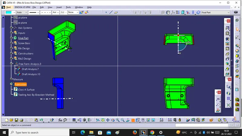
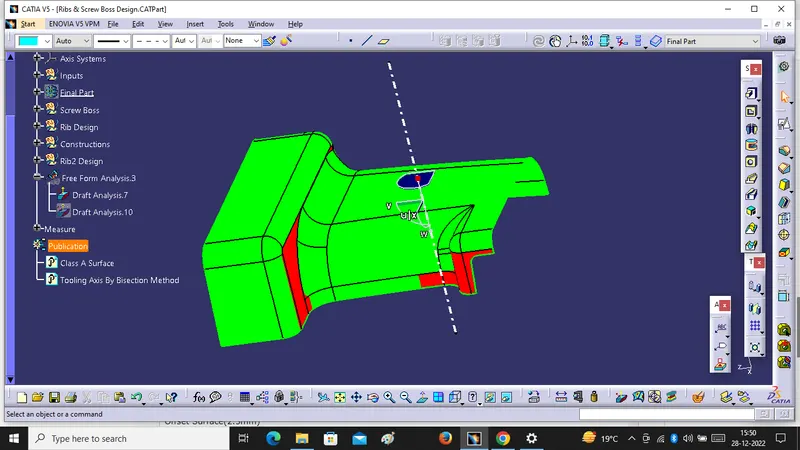
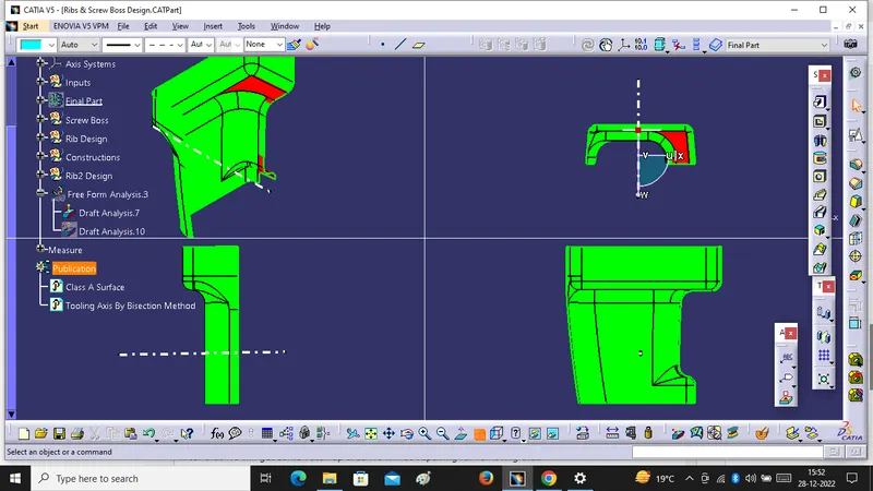
For, Tooling Axis We use Bisection Method, Normal To Surface Method , Point & Direction Method but in Draft Analysis Some Surfaces give Red Colour in all Tolling Axis , So Some Surfaces Shown Red Colour in 3 Deg. But We Will Prefer Bisection method Tolling Axis. The Problem in the Given Class A.
Draft Analysis for Class A Surface:
Step2.
B Surface Creation
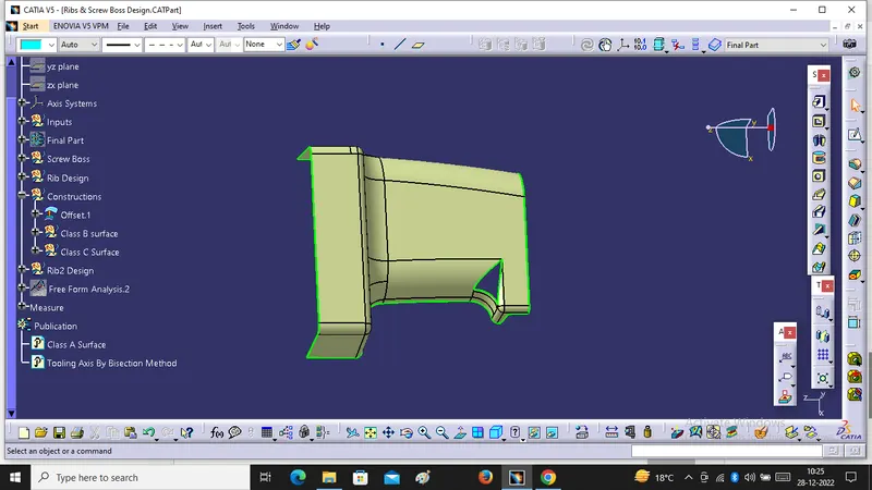
We have to create B Surafce from given class A for that we have to Offset class A inward direction for 2.5mm . After that we will get some Patch up area we will do repairing for removing that.
Offset Surface(2.5mm)
1st Patch Up Repair
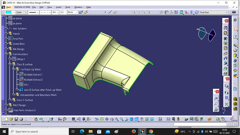
For removing the patch up area we have to use multiple extract and fill after that we will join fill with offset surface . We will get the Surface with no patch up Area.
Extrapolation & Boundary:
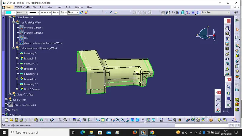
After that we have to take Boundry and Extrapolate them. We will get the B surface Which will Intersect with Class A & Surface Joining.
C Surface
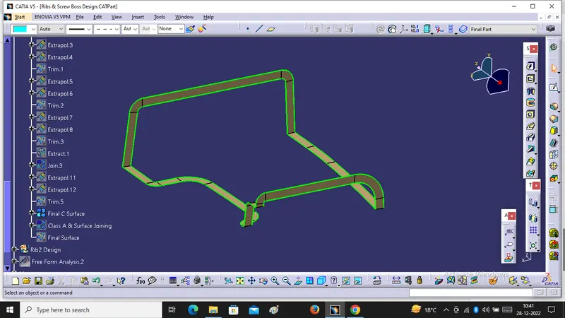
For C surface Creation We have to take Boundary from Class A surface and Create Sweep at 93deg for 4mm after that we got green lines on some edges we will extrapolate them and trim them we will Final C Surface.
Class A & C Surface Joining:
After Creation Of C Surface We Will Join it with given Class A Surface.
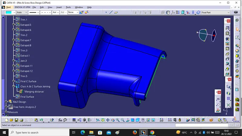
Final Surface:-
For final Surface We have to Trim class A & C Surface Joining With Class B Surface.
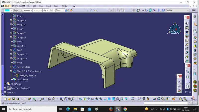
Close Surface:-
For Close Surface We have to go into the Part Design and Select the final Trim to convert it into the close Surface.
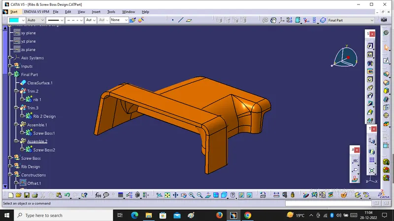
Rib Creation:-
For Rib Creation , We have to do some calculations as well as we have to follow some design guidelines.
Calculations:-
(a) Rib Thickness=0.4*thickness of the component=0.4*2.5=1mm
(b) Rib Height=5 times the thickness of the component=5*2.5=12.5mm
(c) Draft Angle=0.5 degree
(d) Fillet Radius=0.25mm
. We will extract the base Surface, Create Sketch on it and Extrude the Ribs along the Tooling Direction. After that We Will Provide Draft of 0.5 Degree and give Fillet of 0.25 mm Radius to all Faces and Trim it with Part Body and Remove the Unwanted Faces.
Draft for Rib
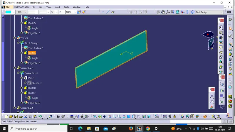
Fillet for Rib
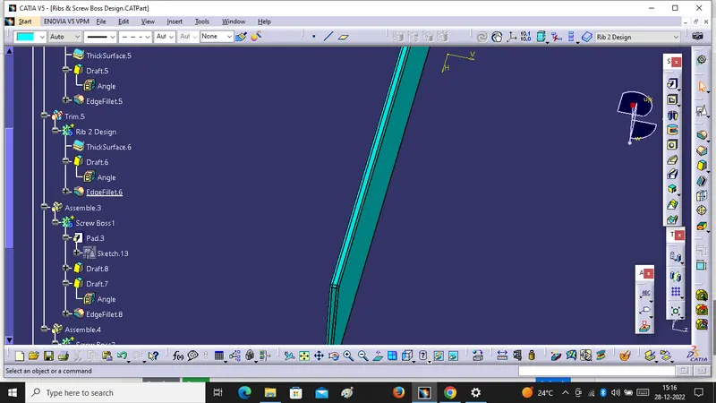
Images Of Rib 1
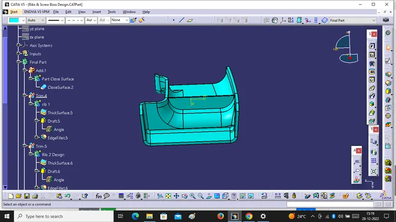
Rib2
After that we will take offset of same line and repeat the same procedure and Create Rib2.
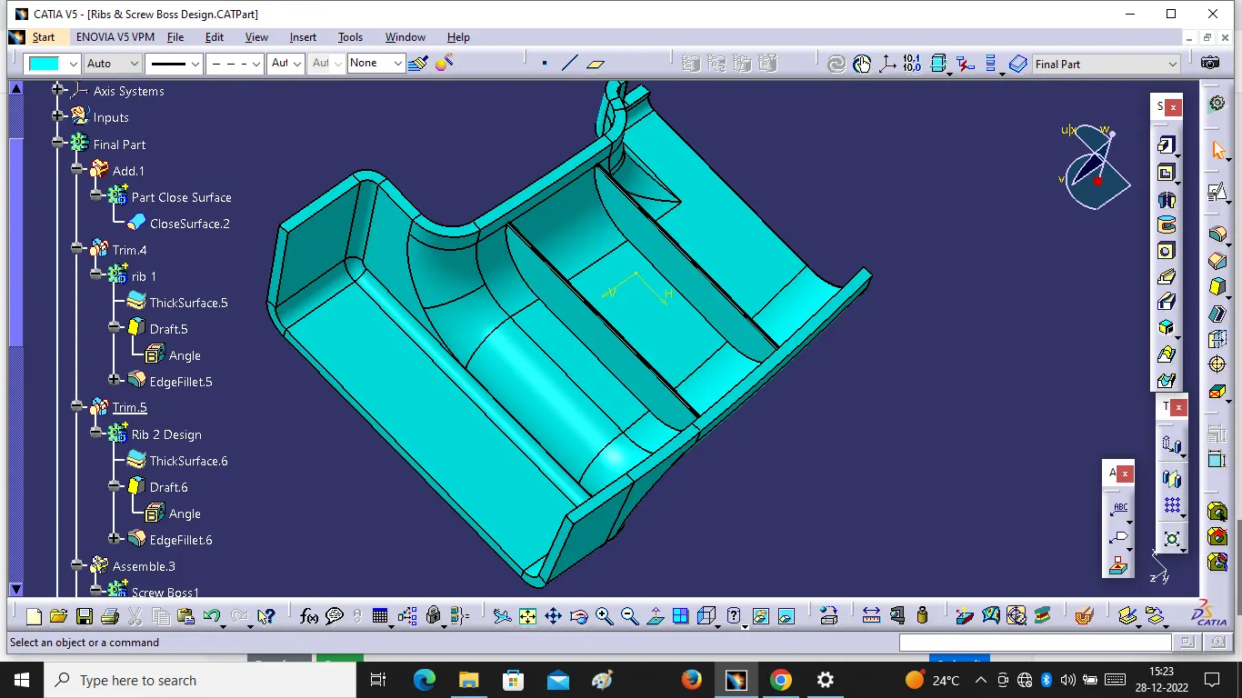
Screw Boss 1&2 :
For Screw Boss Design we have to Extract One Base Surface and Create Sketch of Two circle and Pad it with reference of Tooling Axis. After that, We will do translation of 1st Screw Boss in X direction at Some Distance We will get 2nd Screw Boss.
Calculation for Screw Boss:
we will Consider M6
So, 1st circle Dia=5.2mm
2nd circle Dia =5.2+3mm=8.2mm
Translation Distance in x Direction=40mm
Draft Angle=0.5 Deg
Fillet Radius=0.25mm
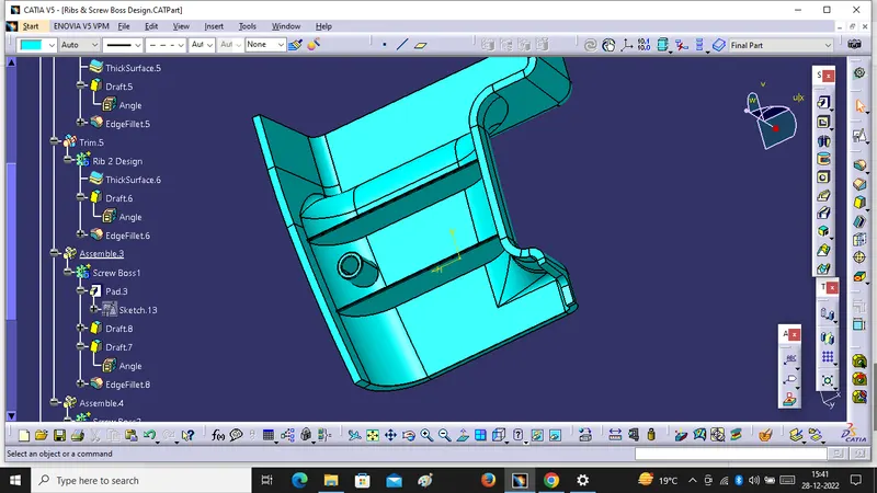
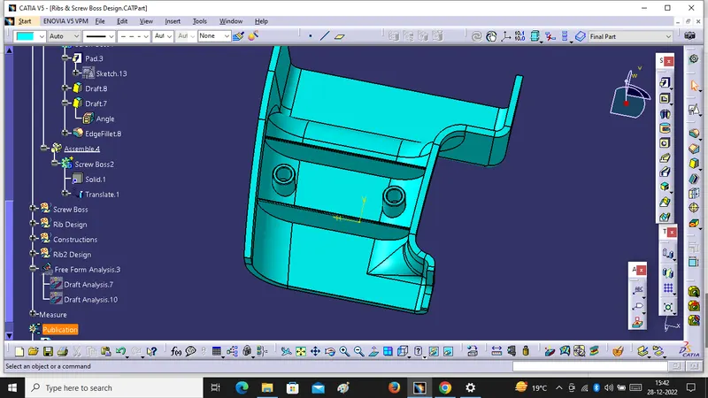
Draft Analysis For Close Surface, Ribs & Screw Boss :-