Week 9 - Attachment Feature Creation (Ribs & Screw Boss) - Challenge 1
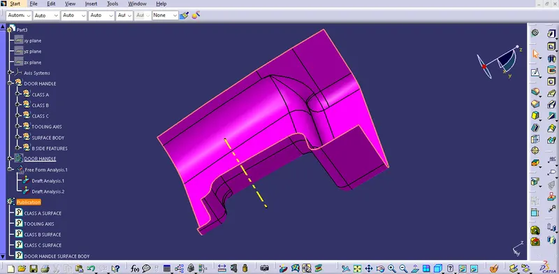
TOOLING AXIS CREATION
Tooling axis defines the movement of tooling (core & cavity).
First seek for the best possible direction for tooling axis.
Generally tooling axis is either in X, Y or Z direction whichever is best for tooling clearing.
Bisecting method is used for creating a line as tooling axis between two possible directions through a point.
In this case,
A flat surface at the middle is selected for creating a point for tooling axis.
Create a point at center of that surface.
Introduce an axis system on the point.
First, create a profile of intersection between XY-plane an A-surface.
Two lines are created from the intersection profile which lies on two side walls of the surface.
A line is created through the point on the surface by using bisecting method from the two lines.
Second, create a profile of intersection between YZ-plane an A-surface.
One line is created from the intersection profile which lies on one side wall of the surface.
Another line is created through the point at an angle of 6⁰ in the direction of side wall.
Finally, A line is created through the point on the surface by using bisecting method from the two lines.
Bisecting line is taken as the tooling axis for the component.
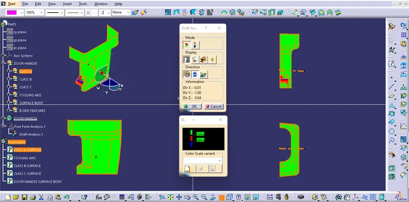
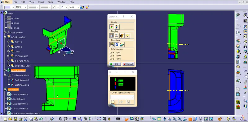
DRAFT ANALYSIS
Change the view mode to Customize View Parameters and select the Material option from the Mesh.
Introduce the compass, drag and align it with the line (tooling axis).
Lock the direction of the draft.
Draft angle compared within 0⁰ to 3⁰.
============================
TOOLING AXIS
DRAFT ANALYSIS
CLASS A SURFACE
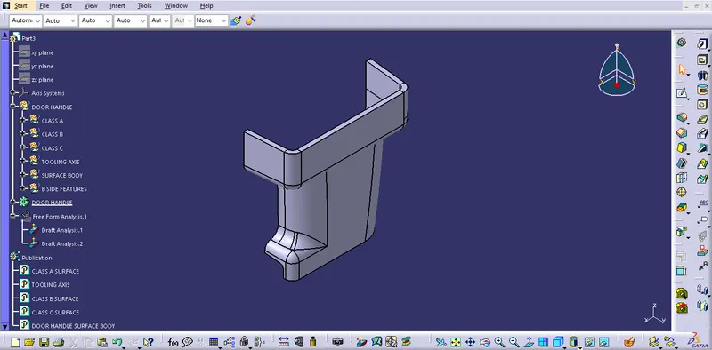
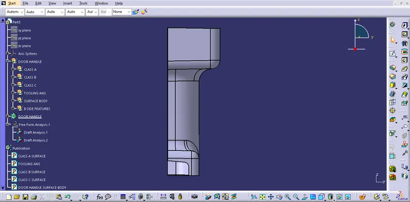
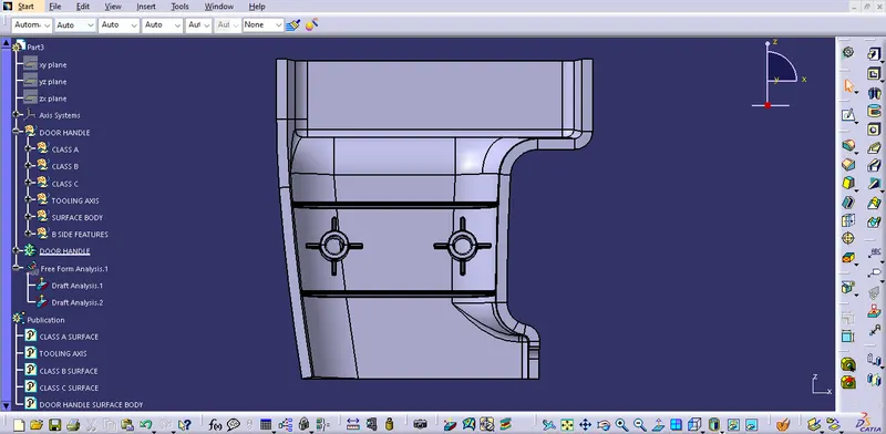
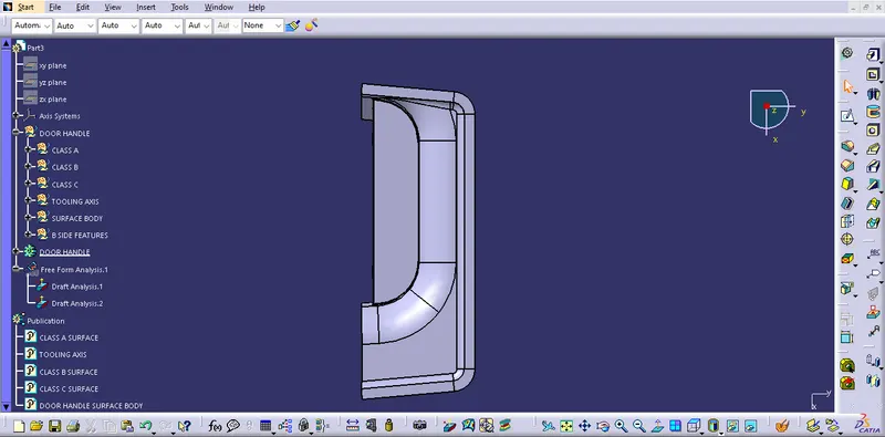
FINAL COMPONENT
ORIENTATIONS
=================================