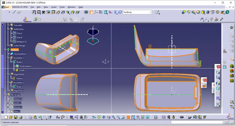
Week 9 - Attachment Feature Creation (Ribs & Screw Boss) - Challenge 1
AIM :
To create rib for center coin holder by using design rules.
SHORT NOTE :
We know that class A is an aeasthatic aurface and class B is an engineer surface,In class B contain all enigineer data.Here some desigining feature they are
- Ribs
- Screw boss design
- Dog house design.
RIB DESIGN :
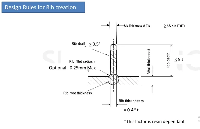
Ribs provide a means to economical stifness and strength in molded parts without increasing overall wall thickness.They also facilitate.
- locating and arresting components of an assembly
- provinding alingment in mating parts
- act as stop or guides for mechanisms.
PROPER RIB DESIGN INVOLVE :
- Thickness
- Hight
- Location
- Quantity
- manufacturability.
PROCEDURE :
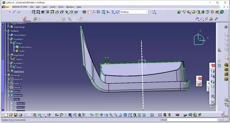
- Extract the base in solid part and insert point in center of the surface.
- By using axis system insert positioned skectch use extract surface in x-z axis.draw a line and constraint it.
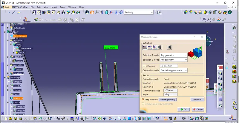
- Extrude the sketch in tooling direction we need to use design rule that 5*t,t=2.5mm.
- Part design->Insert-> body thicken the extruded surface as per design rule 0.4*t is the thickness of wall.
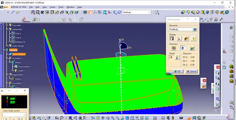
- Now we have to work other feature to make fit to the production, give draft of 0.5 deg in tooling direction.
- Fillet the rib under design rule value of 0.25mm.
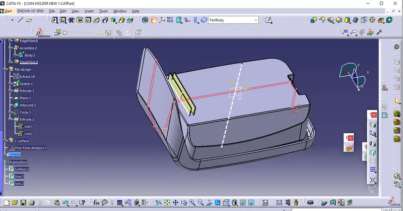
- For rib 2 follow the same step which we follow in rib 1 instant of creating sketch for 2nd rib use translated option.
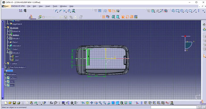
- Height between two ribs is height/spacing=3,we know that height = 12.5mm,space =x.
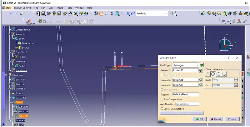
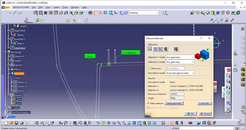
- To know the rib root thickness first instersect with the plane of axis system then draw a circle choose tri-tangent and select element 1,2,3.measure circle value it should under design rule if not correct it and make it under design rule.
- we know that wall thickness is 2.5mm,the diameter should not be more or less then 30% of the wall thickness.
2.
3.
4.
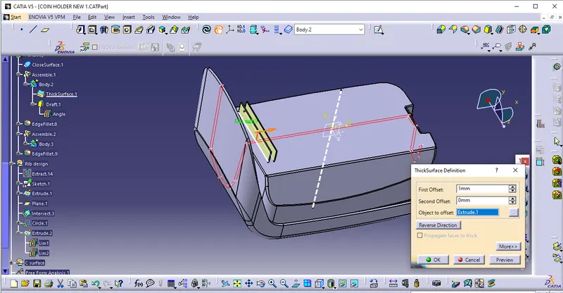
5.
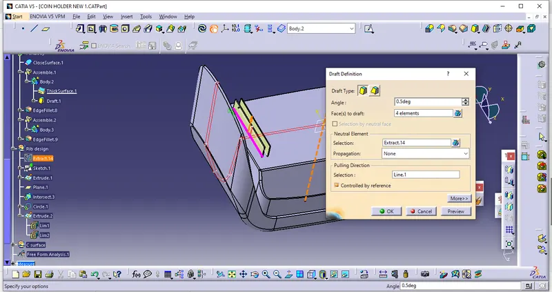
6.
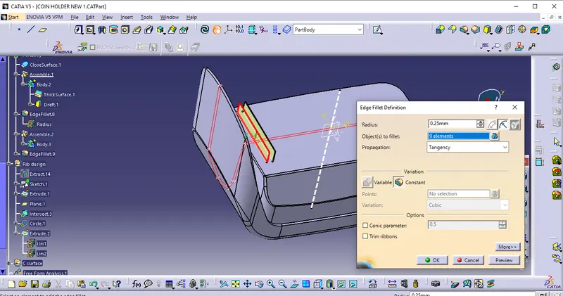
9.
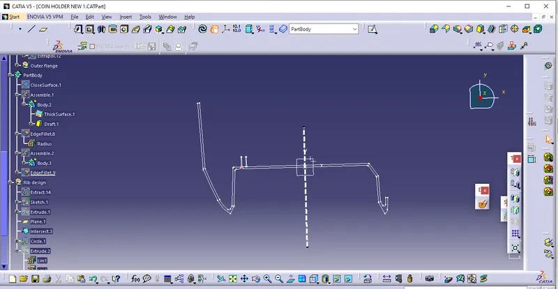
10.
8.
DRAFT ANALYSIS :
MULTI-VIEW :