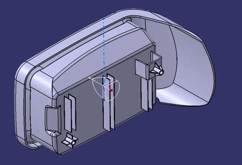
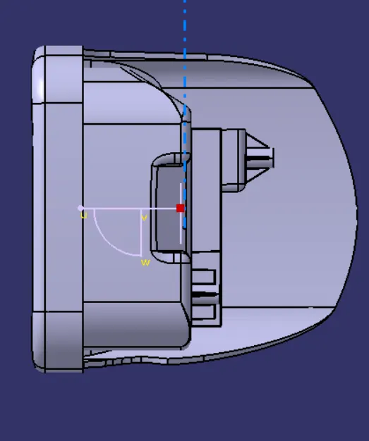
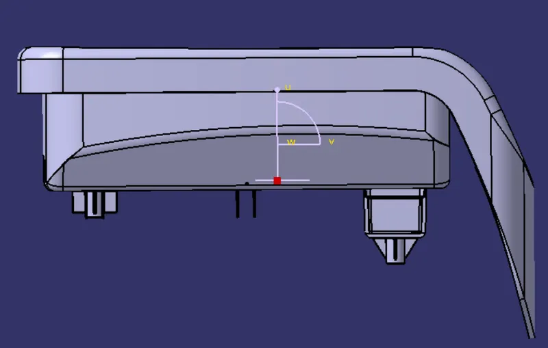
Week 9 - Attachment Feature Creation - Challenge 2
Design of Ribs
A class - A surface has been provided to me for designing a full solid body out of a surface and Validate it.
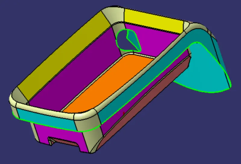
In this given surface first I need to check any open boundaries that may create errors while designing.
- After checking I need to create a Tooling Axis for the Class - 'A' surface.
Tooling axis creation
The tooling axis is the direction of drawing a sheet metal where the finished component is easily ejected on a particular direction and axis. The tooling axis is important for removing the material when finished.
- First, I will create An Axis system, from that axis system I will get two cross-sections. by using that cross-section lines I will create the tooling axis for the surface.
Taken Cross-section along ZY plane
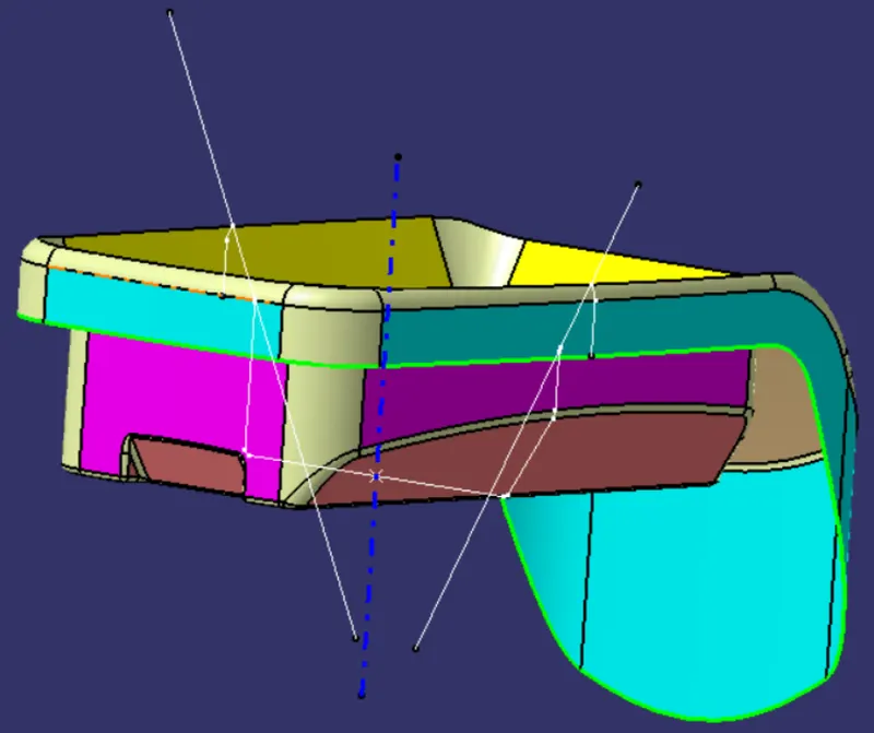
Clearing toling Axis along Y direction
- Now creating a Cross-section along the ZX plane
Clearing the tooling axis along the X direction
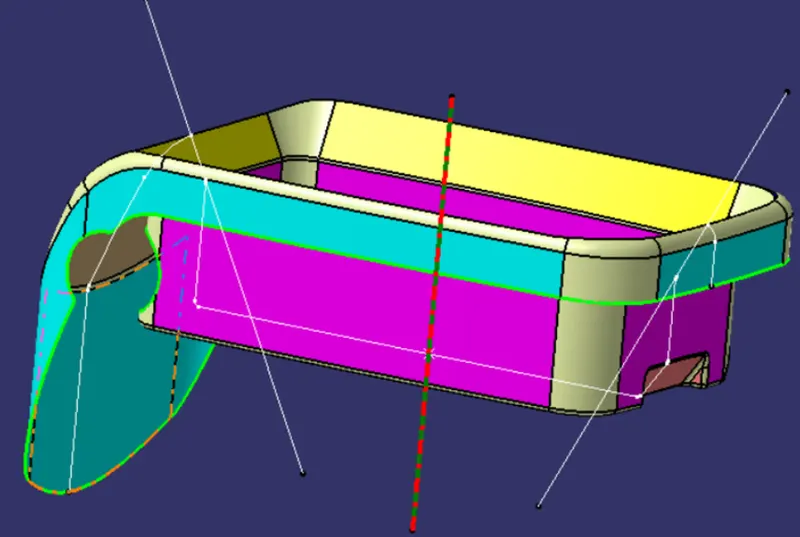
- then using both tooling axis I can now create the main tooling axis for the class - A surface by the bisecting method.
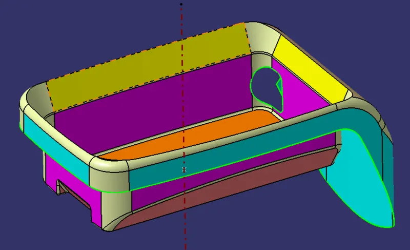
- After the creation of tooling Axis, I will now perform the draft analysis for the provided class - A surface.
From the created tooling axis, There is no negative draft, if viewed from the top.
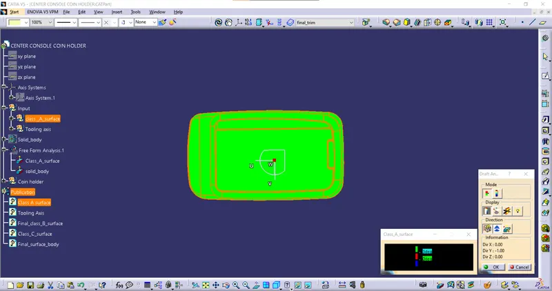
but if I examine the model briefly it has some negative draft.
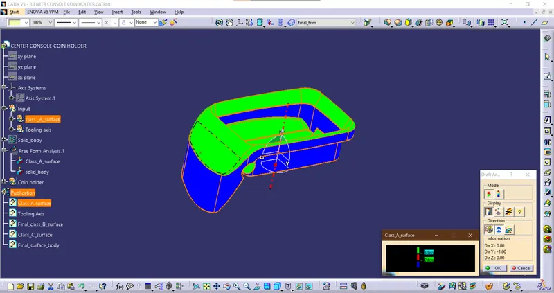
after the errors now I may create a secondary tooling axis ( side core tooling Axis), but for that also there should be a minimum of 3-degree draft angle on all the negative sides of this model.
So when I briefly examined the model I observed that the sides have 0 or negative degrees from the tooling axis.
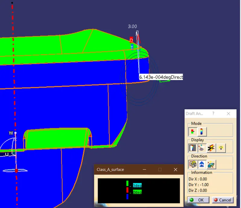
As we can see, these blue surfaces are almost or equal to 0 degrees.
- Now, this is an issue because it will not compete with the recommended classifications of a plastic part manufacturer.
- If the surfaces are at 0 degrees the plastic part won't eject at the end due to contraction after the cooling process.
To tackle this problem there are mainly two reasons which I have come to know.
- one way is to create a secondary and tertiary side core tooling axis to overcome this problem, but the overall point is to manufacture the product with fewer expenses.
- So what I would recommend to the Class - A surface creator to give some draft angles on these sides for 3 to 7 degrees draft to negative sides.
Final model. After designing the Class - B and Class - C surface I will now continue to the designing of Ribs
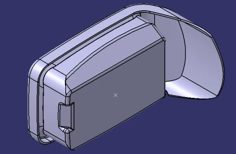
In the previous challenge, I designed the ribs.
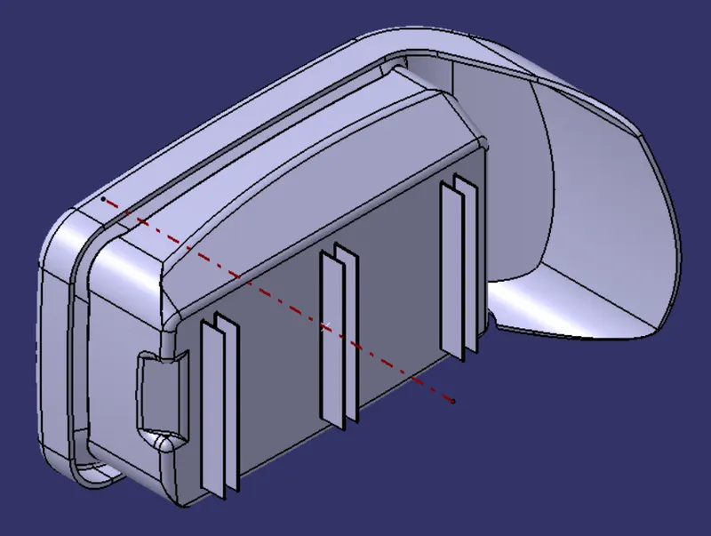
- And now I'm Going to design the Screw boss and Dog house for the Following Plastic model.
- Screw boss design rules
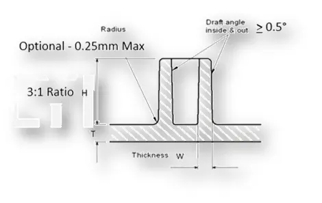
(Image obtained from the Skill Lync design classes)
- First I Sketch the lines required for screw boss.
I have taken the M6 standard for designing the screw boss
- the wall thickness for the Screw boss should be calculated as
Thickness (w) = 0.6 x t ( wall thickness of the part)
= 0.6 x 2.5
w = 1.5 mm ( for single side)
= 3 mm for both sides
so, the overall wall thickness is
= 5.2 + 3
= 8.2 mm
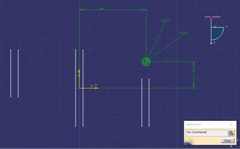
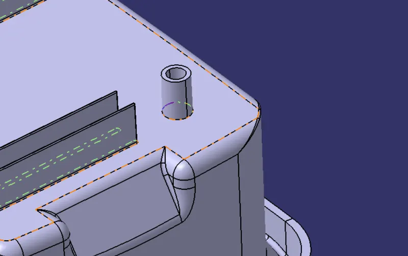
and after that given draft for the screw boss, the next step is to create the ribs for the screw boss
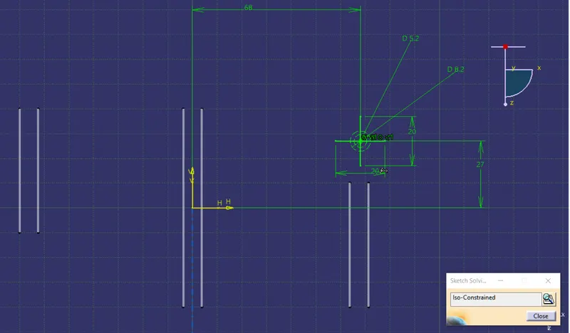
the Height of the screw boss should be 3:1 ration to the wall thickness and hole size.
after extruding the min of 0.5 draft angle is given to all faces of the screw boss.
the thickness can be given as same as the rib thickness given for the other ribs which are 1mm. and given fillet value of 0.25 to all edges
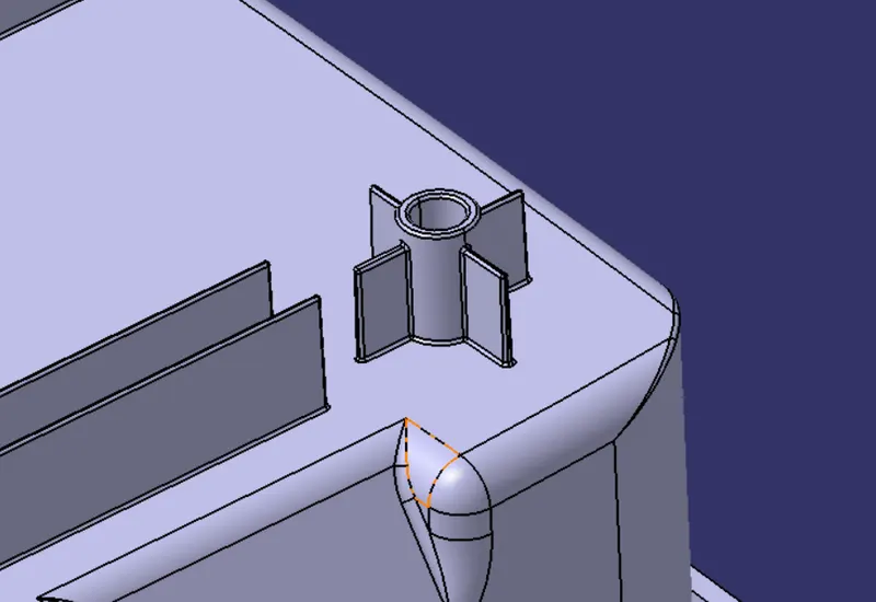
2. The next step is to Create the dog house for the plastic part
the function of the dog house is to elevate the screw boss or any other part to touch the datum surfaces. in some cases, the fixing part is not touched by the plastic part to tighten, so a dog house is used to resolve this problem.
the design rules for creating the dog house is;
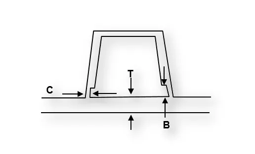
The intersection part where the main part and dog house meets should have the 40% of thickness to the main part.
and the height of that intersection should be 3 to 6 mm.
The thickness value at the intersection is 40% of 2.5 mm
which is 1mm, and after applying the draft value the thickness at one side is 1 mm and at another, it is 0.77 mm.
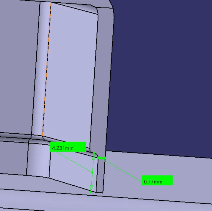
the dog house design satisfies the design rules.
And above the dog house, the other screw boss is designed to touch the datum face of opposite component.
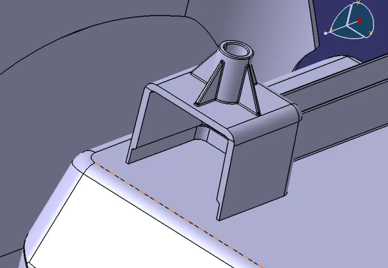
Now creating a tooling axis for the dog house.
90 degrees to the main tooling axis is the side core tooling axis.
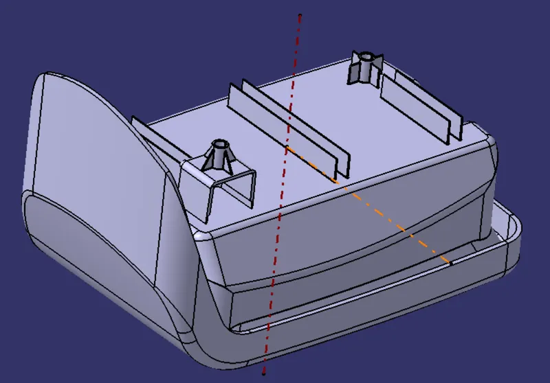
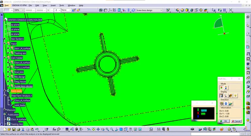
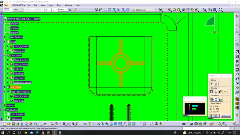
After finishing the product applying the draft analysis to see if there is any negative errors.
- First for the screw boss
- And now for the Dog house inner part,
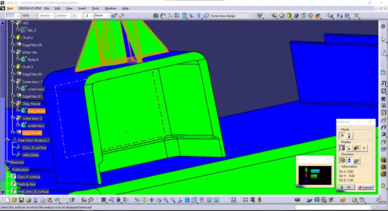
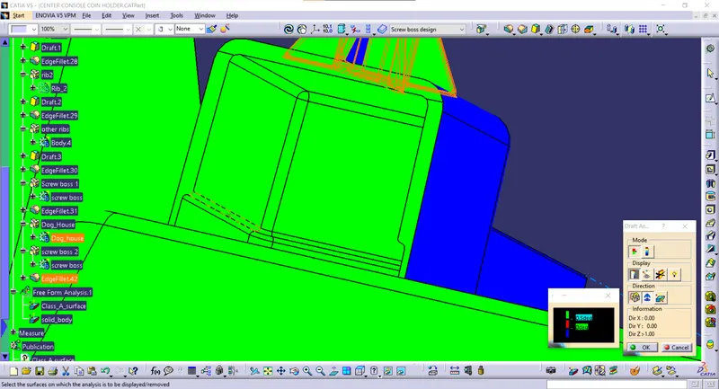
Various views