Week 9 - Attachment Feature Creation - Challenge 1
To create ribs on coin holder model using design considerations.
Objective: Creation od rib can be done to the solid model of any component. The ribs are designed on B side surface. That's why ribs are known as B-side features.
Usage of ribs:
Ribs provide a means to economical stifness and strength in molded parts without increasing overall wall thickness.
They facilitate:
- Locating and arresting components of an assembly.
- Providing alignment in mating parts.
- Acting stops or guides for mechanisms.
Issues that cause while designing proper rib:
- Thickness
- Height
- Location
- Quantity
- Manufacturability
Points to remember:
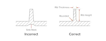
- Due to more thickness to rib, sink marks are caused.
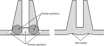
- If the distance between two ribs are less, sink marks are formed.
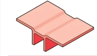
- Maximum Rib height can be five times as component thickness.
Design rules for designing a rib on any component:
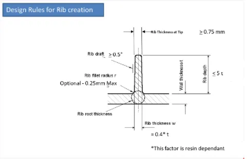
Steps involved in Rib creation:
- Thickness(t) = 2.5mm
- Rib draft - 0.5 degrees
- Rib filler radius (r) = 0.25 mm
- Rib root thickness should be > 30% of thickness
- Rib thickness(w) = 0.4*2.5 = 1 mm
- Rib depth = 5*2.5 = 12.5 mm (considering minimum value)
- Spacing distance between two ribas can be calculated using the relation
Rib depth/Rib thickness ≤ 3 - Equating the Rib depth (w=12.5mm) and considering the ratio value = 3mm and we get
W = 12.5/3 = 4.166 mm
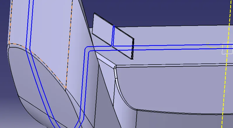
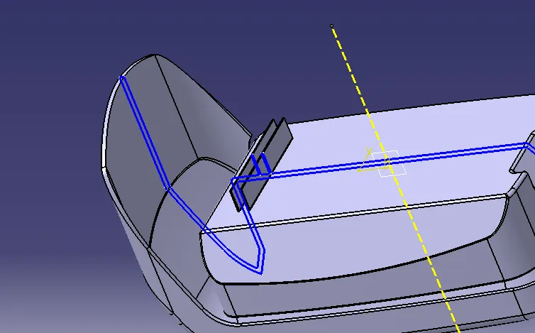
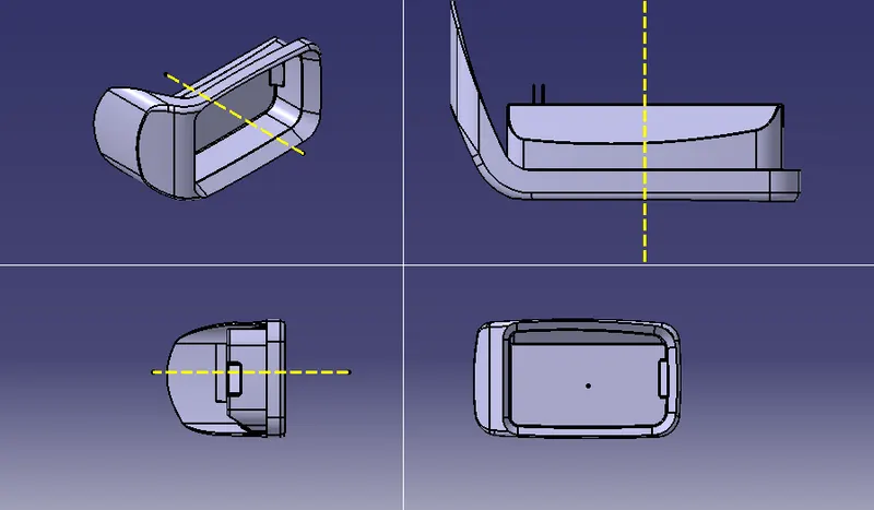
Sketch on bottom face of coin holder is drawn for rib creation. Extruding in the direction of tooling axis.
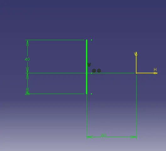
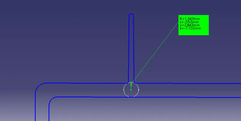
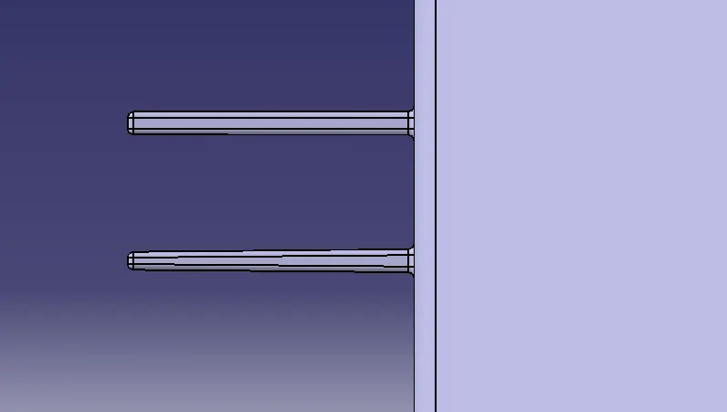
Creating a rib by extruding the surface and giving values acoordingly. After taking intersection with the body, we get rib root thickness as 2.68 mm as diameter, which can be considerable.
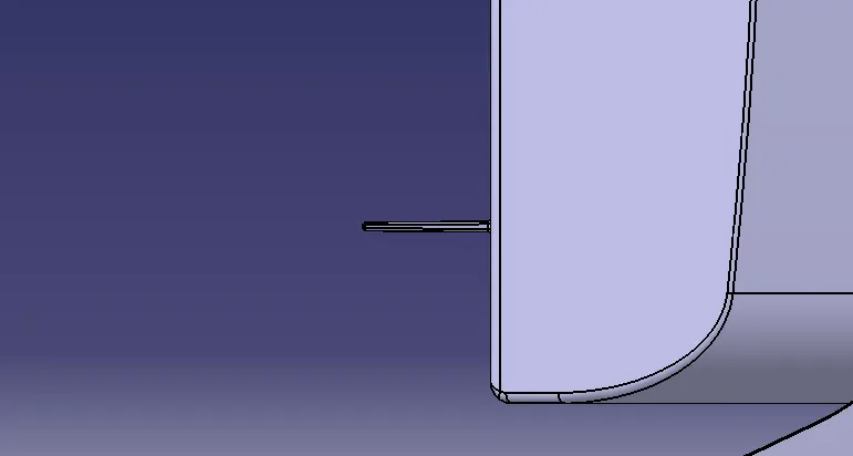
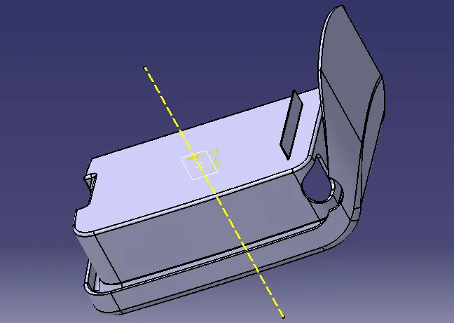
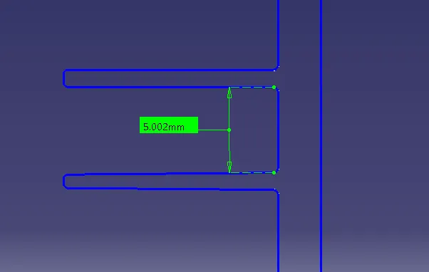
The distance between two ribs should be greater tha 4.16 mm according to the calculation.

Conclusion:
In this way, ribs are created on bodies with design considerations.