Week 9:- 2D Detailing Challenge
What are the Drawing templates?
- Drawing templates are basically the drawing standards as per the customer's specifications.
- Drawing templates are a format that is used for detailing different parts/ units of the fixture.
- A drawing template file is a drawing file that has been saved with a . dwt file extension, and it specifies the styles, settings, and layouts in a drawing, including title blocks. The default drawing template files are provided as samples.
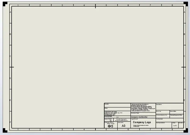
- Company name
- Designer name
- Project name
- Sheet size
- Sheet number
- The angle of projection
- Revision number/latter (incase of revision drawing)
- signature or name of drawn by, checked by, responsible engineer and approved by.
- Parts details
- No. of quantity
- Additional notes
- Remarks
- Scale,date,unit of measurement.
What do you understand by Angle of projection?
Orthographic Projections (two-dimensional views)-
Orthographic projection (or orthogonal projection) is a means of representing a
three-dimensional object in two dimensions.A multi-view orthographic projection is an illustration technique in which up to six pictures of an object are produced (usually three are sufficient in most cases or two in some cases), with each projection plane being perpendicular to one of the
coordinate axes of the object.The views are positioned relative to each other according to either of two schemes.
1-first-angle 2-third-angle projection.
- The angle at which an observer draw an object to convert it from 3D to 2D plane such as real object image to a plane paper is known as angle of projection.
- Projections are basically classified into two:
1. Perspective projection
2. Parallel projection - This is such a type of drawing in which Parallel projection is used for the preparation of the drawing of an object.
- These lines are perpendicular to the plane.
- In this drawing, it is assumed that the object is at infinity.
- The shape of an object is seen in actual size in such a drawing.
- A plane is an imaginary surface on which pictures are prepared imaginably. Then it is transferred to the paper.
- This plane is faced toward the object whose view ia to be prepared.
- Generally 3 views of an object are prepared. These are Top view, Front view and side view.
What is the First angle & Third angle projection? and why can't we use the 2nd and 4th angle of projection?
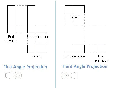
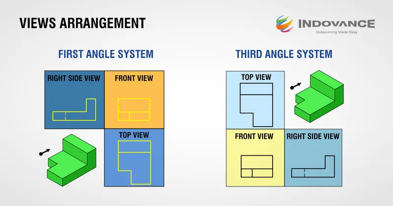
First-Angle Projection: In first-angle projection the object is conceptually located in quadrant I (i.e., it floats above and before the viewing planes), the planes are opaque, and each view is pushed through the object onto the plane furthest from it. The first angle projection is utilized mostly in India and various European countries.
Third-Angle Projection: In third-angle projection the object is conceptually located in quadrant III (i.e., it is positioned below and behind the viewing planes), the planes are transparent, and each view is pulled onto the plane closest to it.
Reason for not using 2nd and 4th angle projection:
- In practice only first angle quadrant and the third angle quadrant are used since these are pure views. The second angle quadrant and fourth angle quadrant are combination of first and third angle projections and cause confusion to the reader.
- 2nd and 4th angle of projection systems are not used because of the limitation of overlapping.
What is GD&T? What are the benefits of GD&T?
Geometric Dimensioning and Tolerancing (GD&T) was introduced by Stanley Parker from Scotland in the late 1930’s. However it was not used to any degree until World War II (WW II) because until then the vast majority of products were made in-house.
It is compilation of symbols and rules that effi ciently describe and control dimensioning & tolerancing for all drawings (castings, machined components,etc.).
1- It is a simple and efficient method for describing the tolerancing mandated by the designer of
the part.
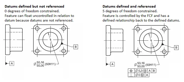
2- It eliminates ambiguities as to what Datum features are to be contacted to establish the Datum
planes and/or Datum axis that are to be used for locating other features. All inspection will
result in the same result – the dimension is within or out of tolerance.
3- It simplifi es inspection because hard gages can often be utilized and inspection fi xtures are
often mandated which simplifi es inspection for production quantities.
4- It forces the designer to totally consider function, manufacturing process, and inspection
methods. The result is larger tolerances that guarantee function, but reduce manufacturing
& inspection costs. Also the “bonus” or extra tolerance for certain conditions can result in
signifi cant production cost savings. In addition the time to analyze whether a missed dimension is acceptable is dramatically reduced.
Benefits of GD & T-
- Accurate production. Since GD&T is such a precisely articulated system of language, it minimizes ambiguity in the description of a Part's Design. As a result, you can be confident that your part will be manufactured with the highest degree of accuracy and work as intended in the field.
- Known tolerances. GD&T gives manufacturers a clear understanding of the tolerances for a specific part. It provides the maximum amount of tolerance for the part to function properly, which reduces Part complaexcity so that you aren’t overspending for a minimum tolerance that you may not need.
- Universal language. You may find yourself in a situation where you want to work with a contract machining company in another country with a spoken language that is different from yours. Great news! GD&T is a universal language widely accepted across the world, thereby eliminating frustrating language barriers for overseas production.
- Precise assemblies. If you have two mating parts that need to come together in an Assembly, GD&T is an excellent way to communicate how this interfacing can best take place. In these situations, GD&T clearly depicts the tolerances of each part so that manufacturers can easily tell if a measurement is off and adjust accordingly.
Explain all the symbols used in GD&T?
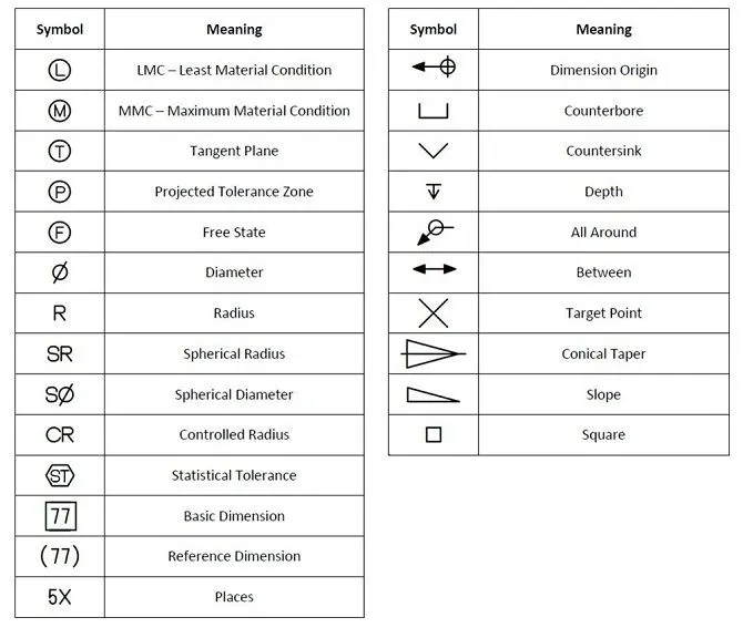
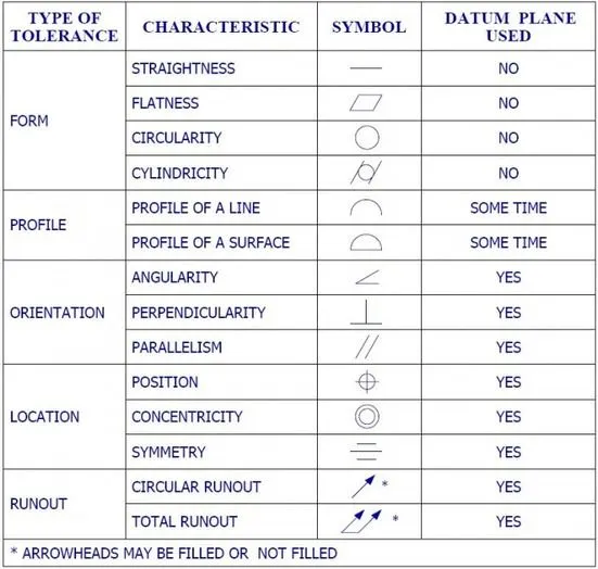
Straightness
To indicate the straightness characteristic of a feature (such as an axis or a surface), we use its symbol (a straight horizontal line) in the first compartment.
Surface straightness can apply to flat surfaces like a side of a block or curved surfaces like a side of a cylinder along the direction of the axis. It defines the allowable variation of a line (2 dimensions) on the surface within a specified tolerance.
Axial straightness usually applies to the axis of a shaft or a hole, for example. Go/no go gauge is the inspection tool used in the process of making sure the part conforms to the demands.
Flatness
We use this characteristic for features such as the face of a part. The symbol for flatness is a parallelogram tilted to the right. The difference between the highest and lowest point of a flat surface is its flatness.
The flatness symbol does not require any datums, as it only shows a tolerance range within which the whole surface of a part must conform to in 3 dimensions.
A height gauge is used for checking the results. It touches upon different areas of the surface to determine that all the points are inside the tolerance zone.
Circularity
The circularity (GD&T) of a feature shows how close the circumference of the part should be to a perfect circle. It uses 2 concentric circles on a plane perpendicular to the part axis to define the suitable tolerance range in 2D. Each point of the final measurements has to fall between the circles.
This characteristic is shown as a circle in the first compartment of the feature control frame.
Cylindricity
Cylindricity is basically circularity in 3D, meaning that it runs along the whole length of the part.
This feature also describes other cylindrical characteristics such as its taper, straightness, and roundness. This is why this feature is also expensive to inspect.
Profile Controls
We use profile controls to control the 3D tolerance zone around the feature. This feature helps us to give tolerance limits to advanced curves and shapes.
A feature that is good for advanced curves must naturally work well with simpler curves as well. This makes profile controls extremely versatile. This is why some designers recommend abandoning all other controls and working only with profile controls.
These controls form a tolerance limit around the advanced curve by mimicking it on both sides. It then prevents any point on the feature curve from going outside the tolerance limit. Profile controls are of two types.
Line profile
Line profile establishes a tolerance zone around varying 2D cross-sections of the part. It controls individual line elements of a part feature.
The line profile control traces the ideal curve at the tolerance limits on both sides. All points on the part’s curve must lie within these limits.
Surface profile
Surface profile control is more popular compared to line control. Instead of a two-dimensional tolerance zone, the surface profile control creates a 3D zone around a surface.
All points on the table’s surface must lie within the two virtual planes.
Orientation Controls
Orientation tolerance controls the orientation of a feature with respect to a defined datum. There are three types of orientation controls in GD&T.
Angularity
The angularity control keeps the angle of a feature with respect to the datum in check. We can use it to control a 2D line, but it is more popular with keeping surfaces (3D) under control.
This kind of tight control keeps the angle and the surface flatness in check and is recommended for part features that mate with other parts through the angled surface.
It is important to note that the angularity feature controls the angle indirectly, not being essentially the same as an angular tolerance (e.g. +/- 2°). Rather, the necessary angle is a result of keeping to the dimensional requirements laid out by this control.
Parallelism
Parallelism is a refined form of angularity. Here, the datum is the surface we need to imitate and the angle is set to 0°. There are 2 types of parallelism: surface parallelism and axis parallelism.
We can choose an axis or a surface as a reference. This becomes our datum and we reference it in the 3rd block of the feature control frame as the datum for the feature.
Similarly to angularity, it does not control the actual angle but rather secures it by laying out the requirements in the form of a tolerance zone.
Perpendicularity
Perpendicularity is also a specific form of angularity where the angle is set to 90°. It is a tricky control since it can mean two very different types of requirements.
There’s surface perpendicularity ( Symbol:⟂), and then there’s axis perpendicularity (Symbols: ⟂+⌀).
Surface perpendicularity specifies that a surface or line needs to be perpendicular to a datum surface or line much like angularity. Two virtual planes/lines are assumed around the target surface for control.
Axis perpendicularity specifies how perpendicular an axis needs to be to the mentioned datum. This is done by erecting a virtual cylinder around the target axis on a surface exactly parallel to the datum surface.
Location Controls
The Location tolerance control is used for tight control on a feature’s position with respect to a datum. There are four main types of location controls.
Concentricity
Concentricity, also known as coaxiality (even though not exactly the same thing), control maintains the concentricity of circular as well as cylindrical features.
It fixes the axis of a part to the axis of a referenced feature (datum axis). The axes of both parts are determined to be at the median points of the parts.
This control can lead to some confusion because the axes derive from outside measurements, rather than their actual placement.
Coaxiality creates a 3D tolerance zone based on surface measurements that the part must lie in.
Symmetry
The symmetry callout establishes a central plane around which the two parts of the feature are placed at equal distance. The midpoint of the two points on either side must lie within the tolerance zone set around the central plane.
The symmetry callout is not very common. It has very limited uses and is also difficult to inspect. We need a CMM to inspect the final symmetry.
True position
True position (popularly known as position) is a very useful callout and finds extensive use in GD&T.
Position defines how much the actual position of a feature can vary from its intended position. The definition includes the datum plane which the measurement relates to.