Week 8 Worm Gear Challenge
AIM: - PERFORM A TRANSIENT STRUCTURAL ANALYSIS ON A WORM GEAR ASSEMBLY
Objectives:
Perform a transient structural analysis on a worm gear assembly.
Obtain the results for Equivalent Stress, Equivalent Elastic Strain, and total deformation.
To begin the analysis, select the Transient Structural Analysis from the Analysis Systems in the Ansys Workbench.
The material to be used for the analysis is Structural Steel.
Import the geometry into the project environment. Double-click on Geometry to view it in SpaceClaim and to perform certain changes on it.
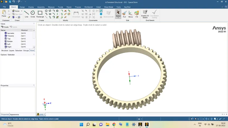
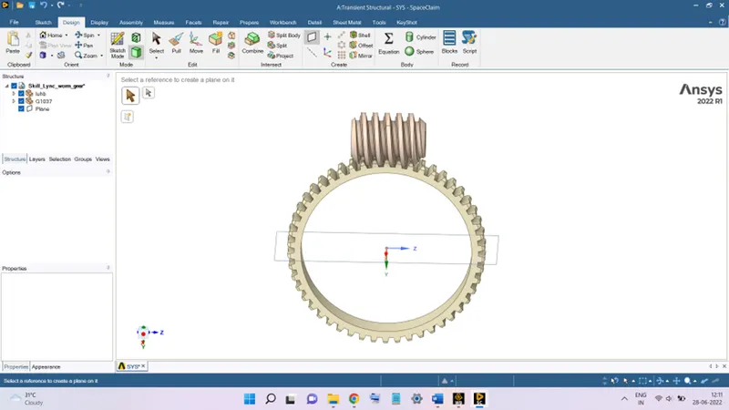
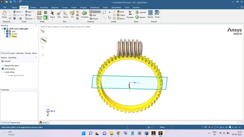
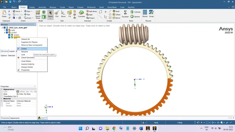
The gear will be cut in half for the analysis. This is done by using the Split Body command and splitting the gear body using a plane and then deleting the lower half of the Gear.
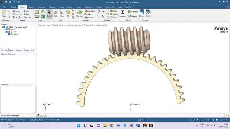
Right-click on Model and select Edit to load the geometry in the Mechanical Module.
Expand Geometry and Rename both parts accordingly.
In the Connections sections, expand the Contacts and select the GEAR surfaces as the Target body.
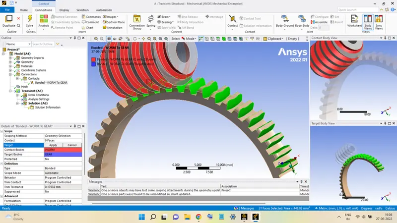
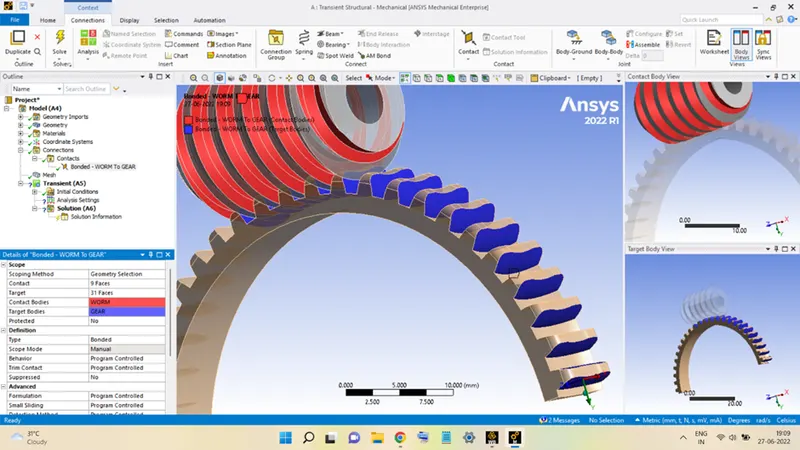
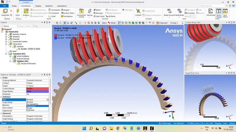
Change the Type to frictionless.
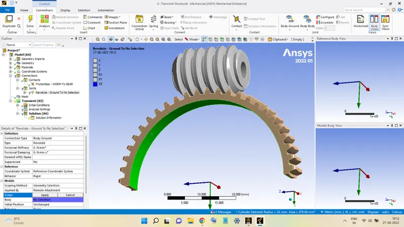
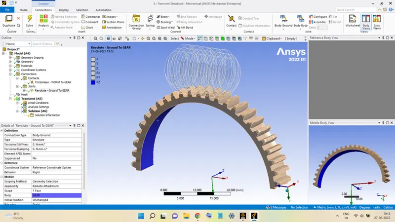
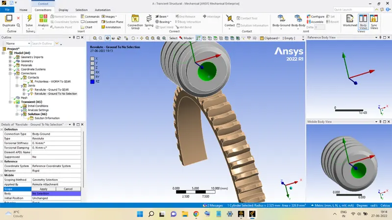
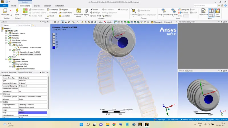
Assign the Body–Ground Revolute joint to both WORM and GEAR, as shown below:
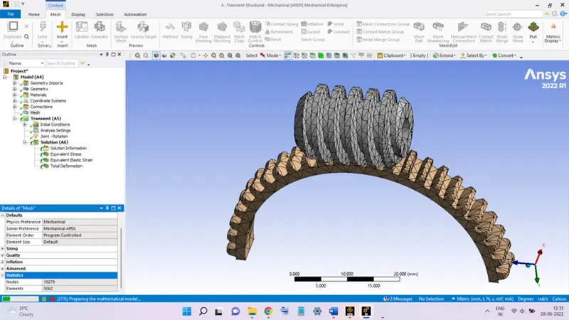
The model was meshed using the default element size, the meshed model will look like this:
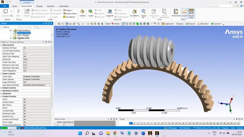
In the Analysis Settings, the Number of Steps taken is 32. The settings for the first step:
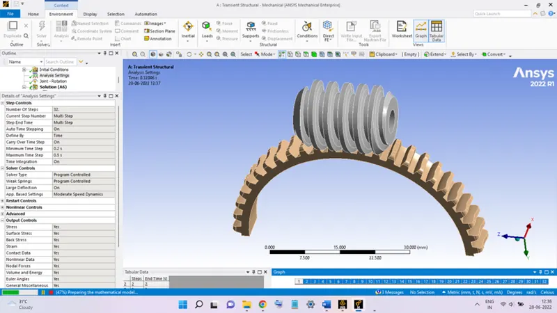
And for the rest of the steps:
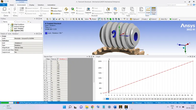
The WORM Body – Ground Revolute Joint is assigned with a Rotation Joint Load about the Z-Axis. The magnitude of the rotation is submitted in Tabular format as shown in the figure below:
Add the required output results into the analysis and hit Solve to begin the analysis.
RESULTS:
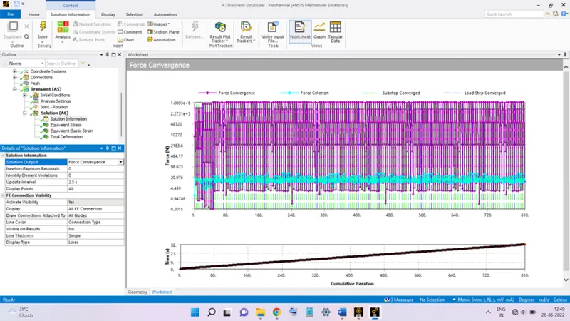
The Force Convergence graph of the analysis is shown below:
Equivalent Stress:
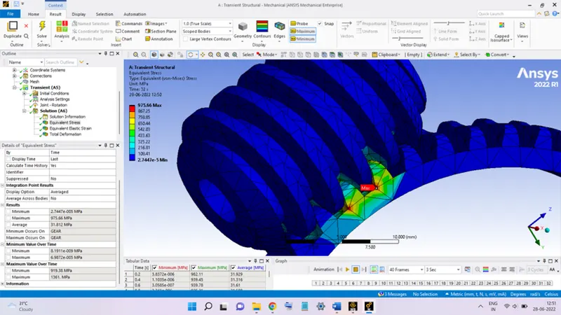
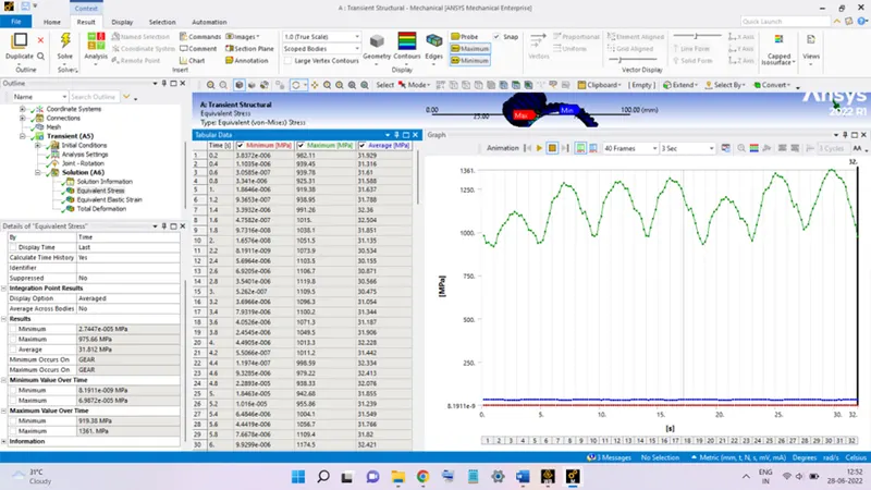
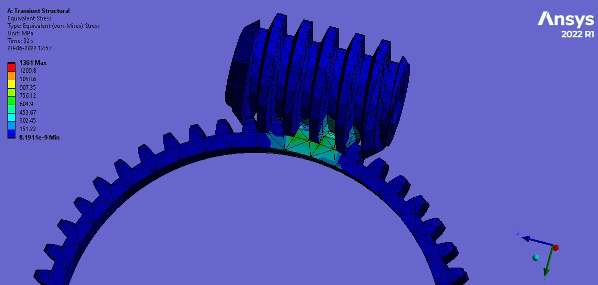
The variation of the stress developed in the assembly during the motion is shown in the above figures. The stress is seen to be maximum near the root of the GEAR teeth which are in mating condition with the WORM, and the magnitude reaches up to 1361 MPa.
Equivalent Strain:
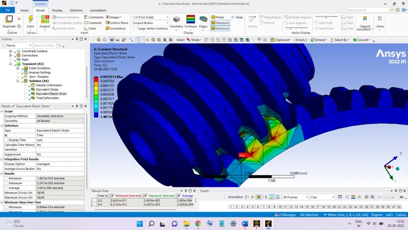
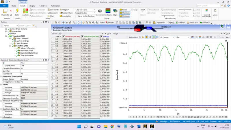
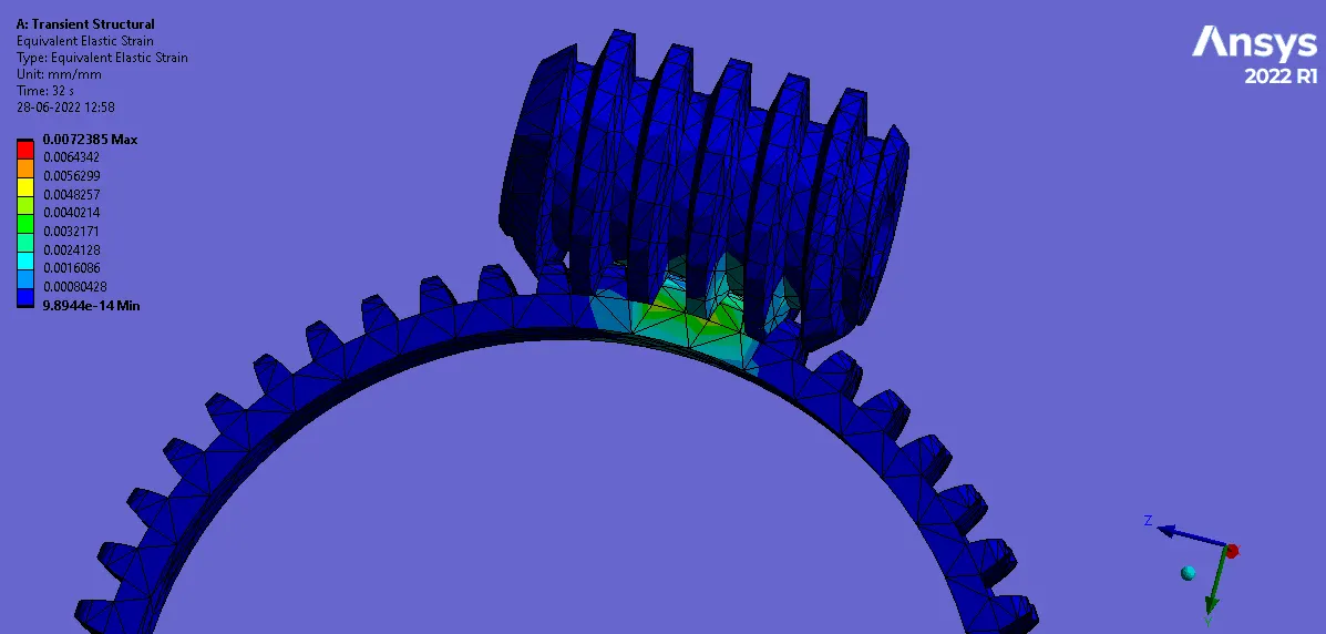
As seen for the stress, the same is also observed for the strains developing in the model. The maximum strain is found to be present near the root of the GEAR teeth with a magnitude up to 7.2385 x 10⁻³.
The variation behavior for stress and strain is the same for both.
Total deformation:
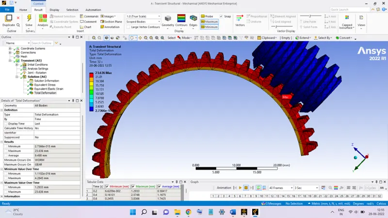
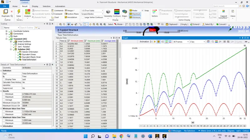
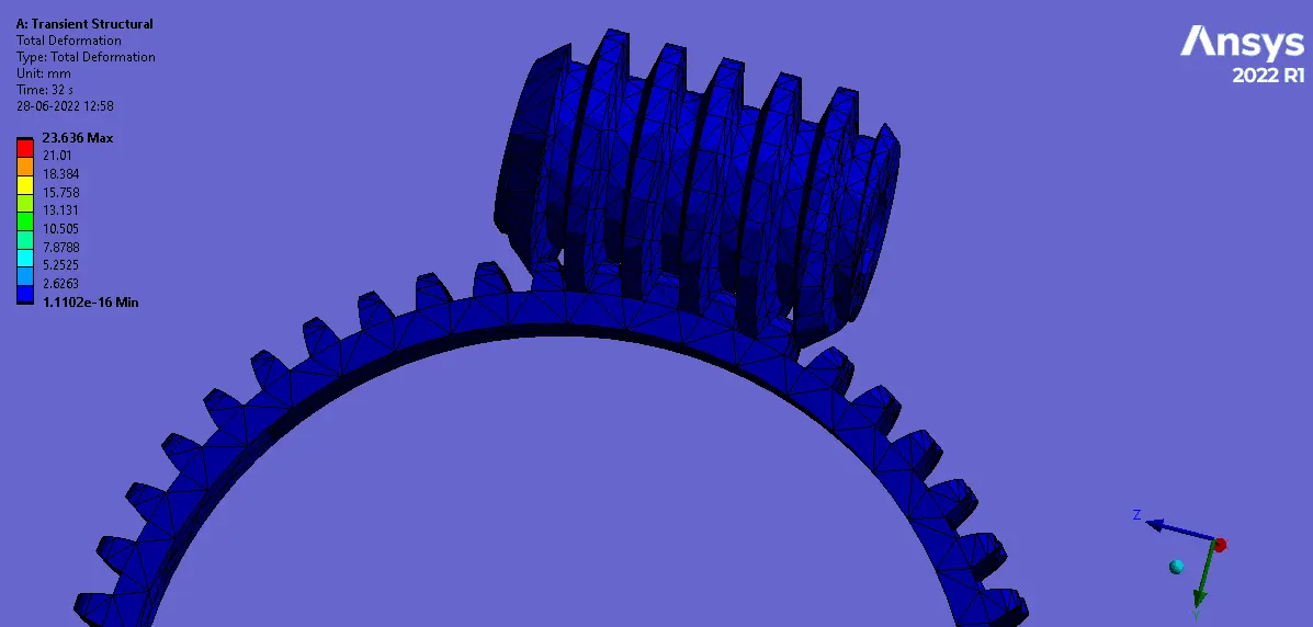
The deformation during the motion is shown in the figures above. The maximum deformation is seen to equal 23.636 mm.