Week 8 - Universal Joint
AIM: - PERFORM A TRANSIENT STRUCTURAL ANALYSIS ON A DOUBLE UNIVERSAL JOINT WITH A SPRING
Objectives:
Perform a transient structural analysis on a double universal joint with a spring using three different materials for the joint with the spring.
Obtain Equivalent Stress, Total Deformation for all three cases and compare them.
To begin with, the analysis, select the Transient Structural Analysis from the Analysis Systems.
Double-click on the Engineering Data and then go to Engineering Data Sources and add the required materials from the General Materials library into the project.
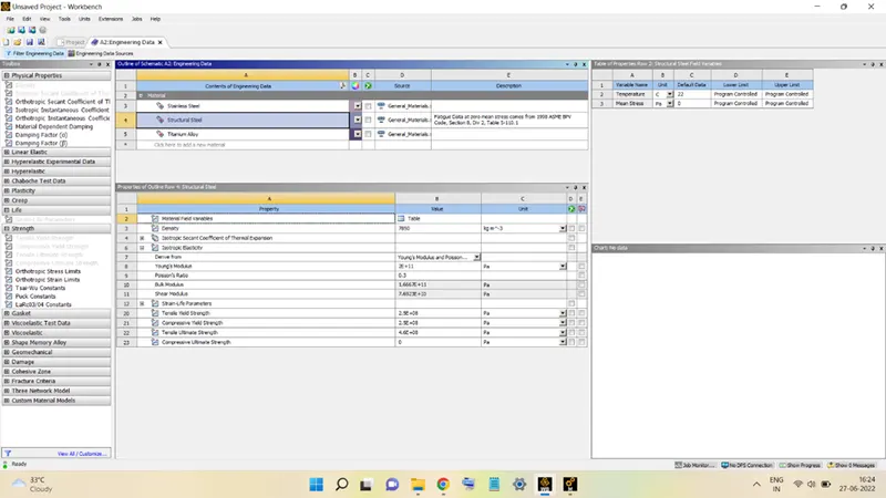
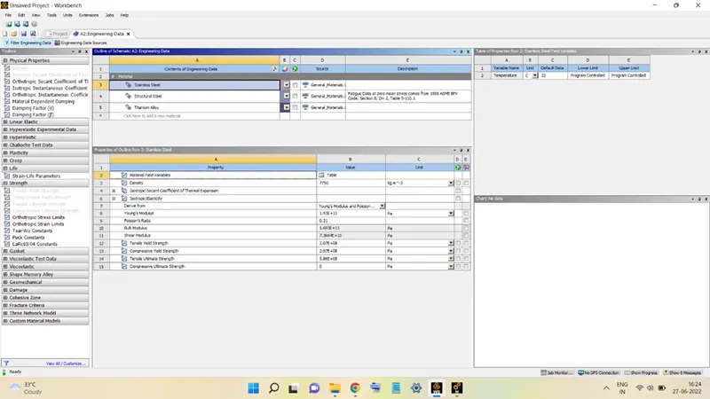
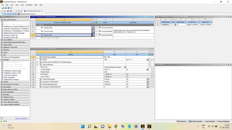
The three materials added to the project along with their properties are shown below:
1. Structural Steel:
2. Stainless Steel:
3. Titanium Alloy:
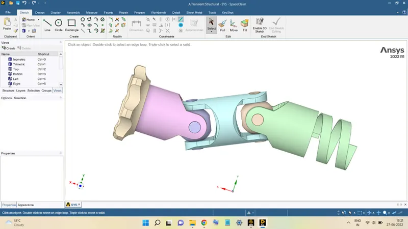
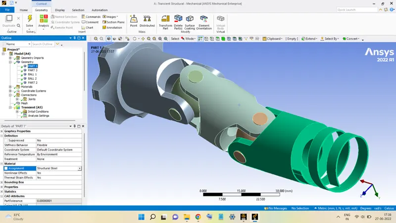
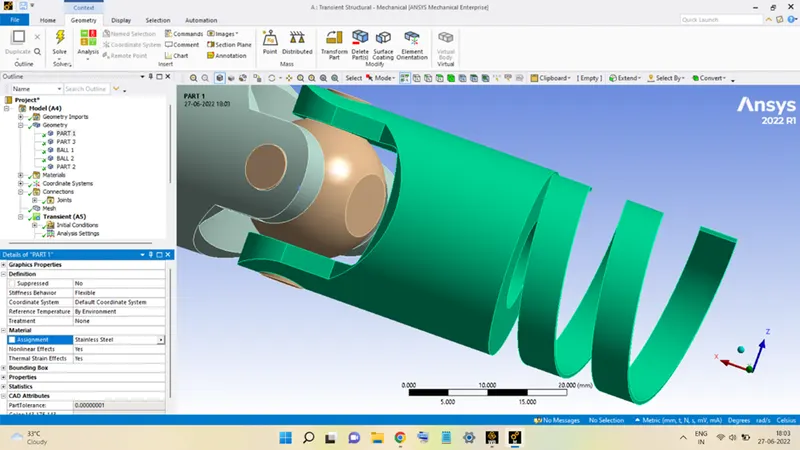
Next, import the geometry into the project. The geometry, in the SpaceClaim, will look like this:
Right-click on Model and select Edit to launch the Mechanical Module and load the geometry in it.
In the module, expand the Geometry and rename the parts accordingly.
Go to the Connections section and delete all the predefined Contacts, if present.
Next, add the Joints between the components of the geometry. The joints added are as follows:
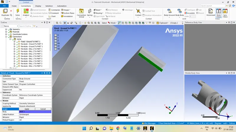
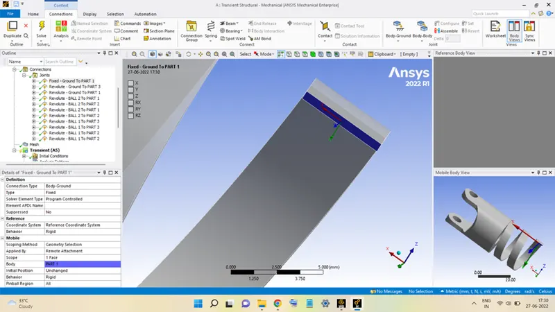
The free end of Spring of PART 1 is Fixed:
The free end of the spring is fixed using the Body–Ground Fixed Joint.
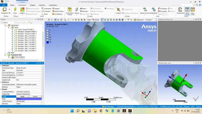
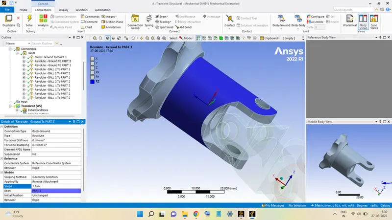
Revolute Joint to PART 3 and PART 1:
PART 1 and PART 3 both are assigned a Body–Ground Revolute Joint, as shown below:
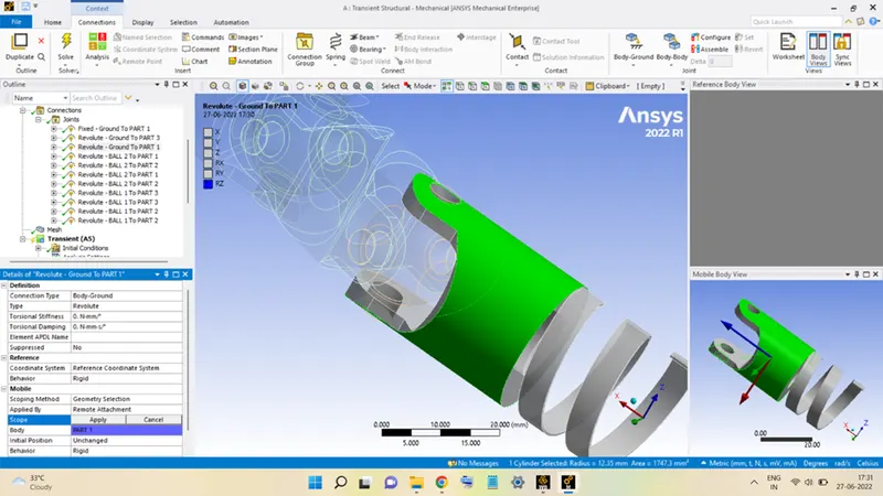
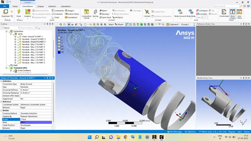
Revolute Joints between the balls and the parts of the geometry:
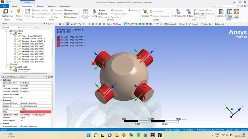
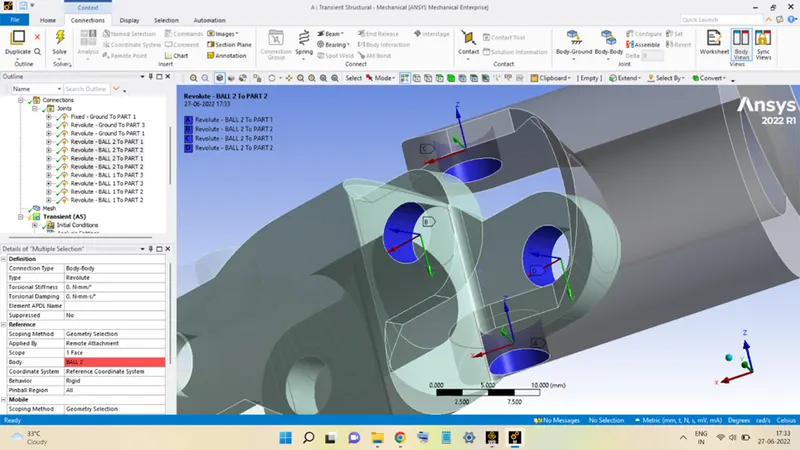
There are 4 Body – Body Revolute Joints associated with BALL 2 and PART 1 & PART 2 such that all the extruded surfaces of the BALL 2 are the Reference Surfaces and the hole surfaces on corresponding parts are the Mobile Surfaces respectively.
Reference Surface:
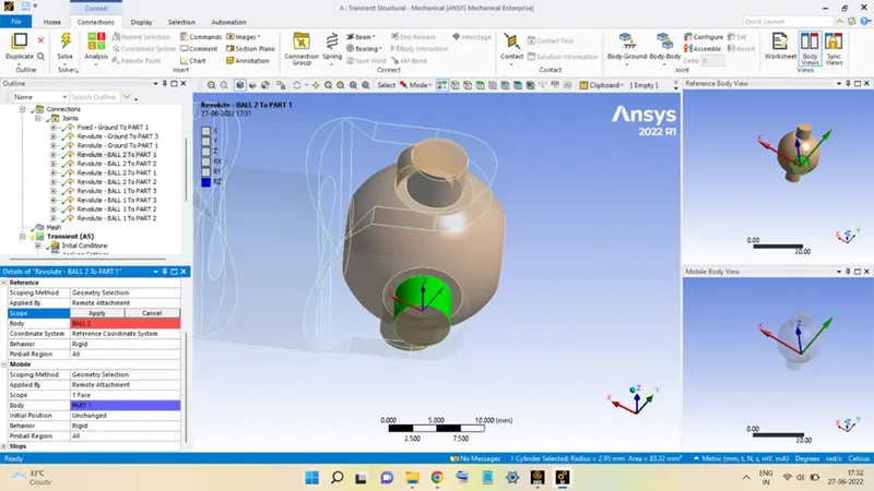
Mobile Surface:
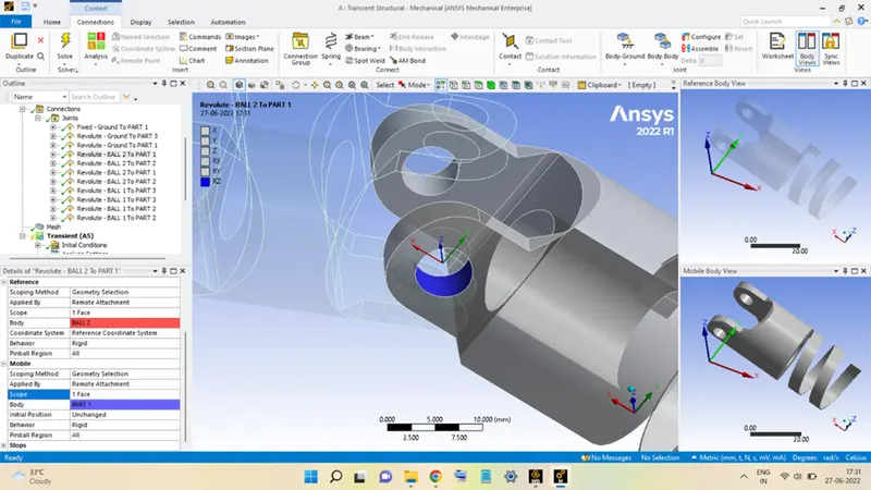
All the Reference Surfaces on the BALL 2 are:
All the Mobile Surfaces on PART 1 & PART 2 are:
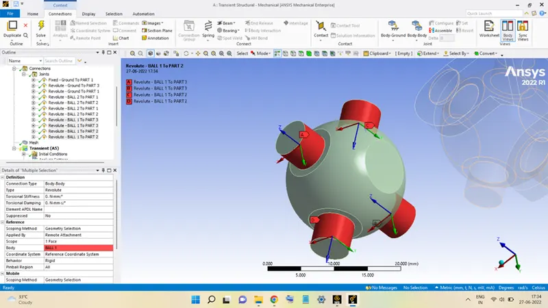
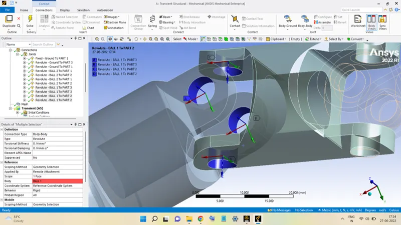
Similar to BALL 2, 4 Body – Body Revolute Joints are defined for the BALL 1 also, as shown below:
Reference Surfaces:
Mobile Surfaces:
The next step is to mesh the model, a 4 mm Element Size is used to mesh the model, and the model with meshing looks like this:
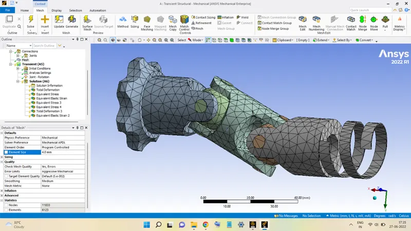
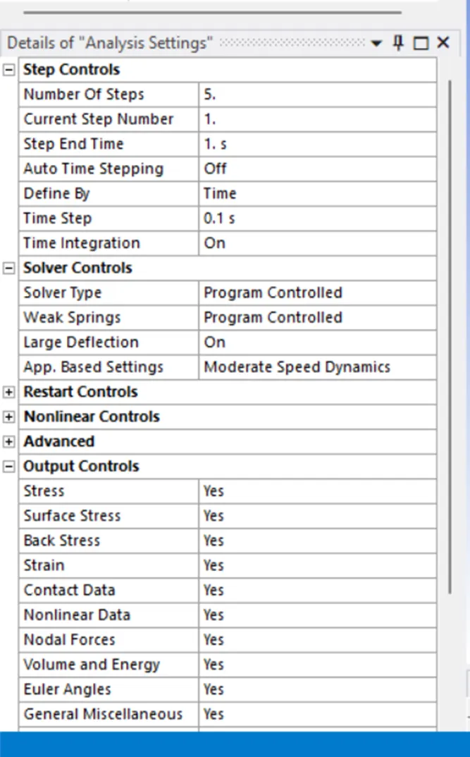
The next step is to define the Analysis Settings. In Analysis Settings, the Number of Steps taken is 5. For the first Step the settings are:
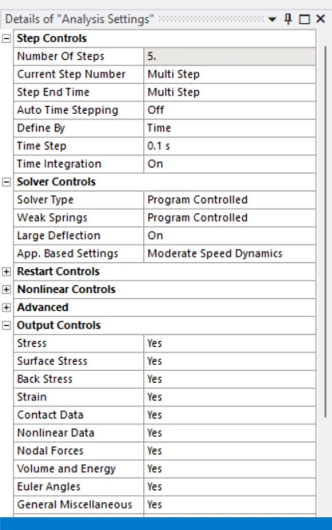
And for the rest of the Steps:
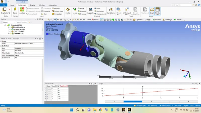
Adding the Rotation Joint Load on PART 3:
A rotation is supplied on the Part 3 Revolute Joint about the Z-Axis. The magnitude of the rotation is supplied using a table, shown in the figure below:
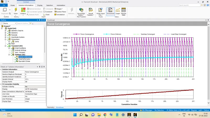
With this, the model is ready for the analysis, hit Solve to begin the analysis. After successful completion of the analysis, the material assignment for the Spring component will be changed and then again solved for all the materials.
RESULTS:
CASE 1: STRUCTURAL STEEL
Equivalent Stress:
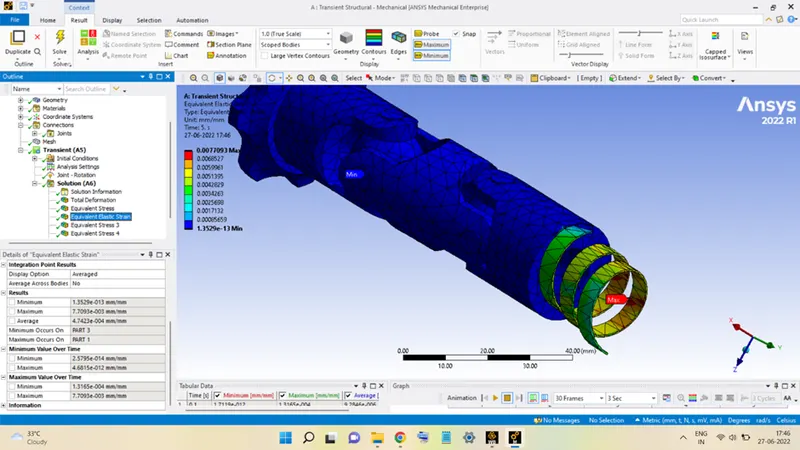
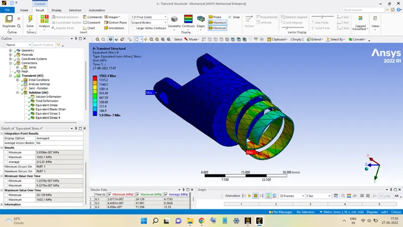
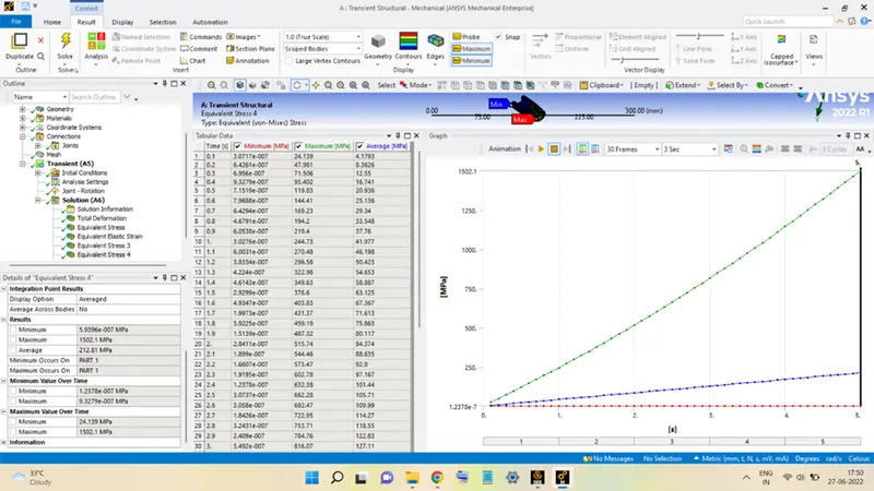
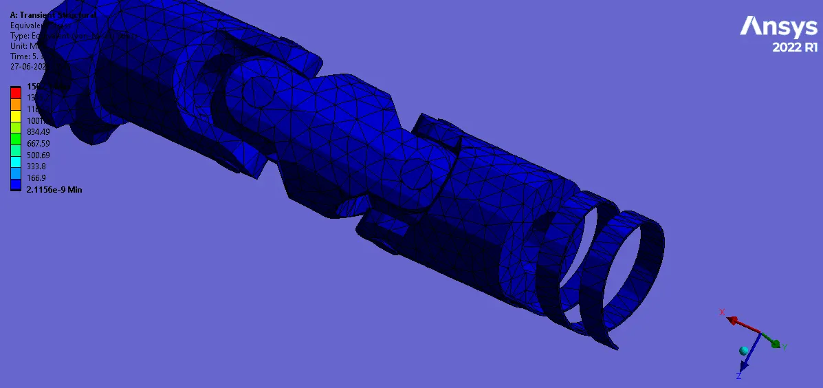
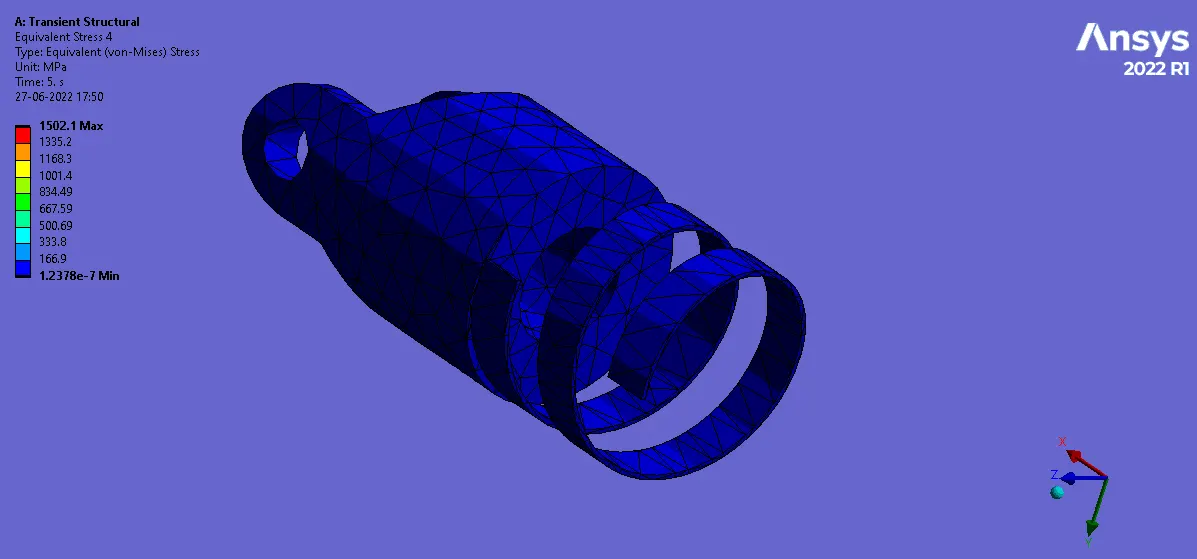
The stress developed in the model is shown in the above figures. The figure also shows the stress developed in PART 3. The maximum stress developed in the spring component, during the rotation is equal to 1502.1 MPa. The stress can be seen to be monotonically increasing in a somewhat linear fashion.
Total Deformation:
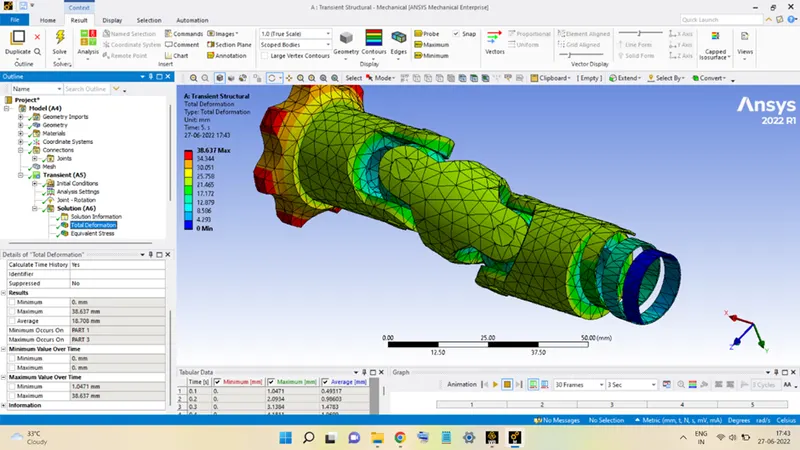
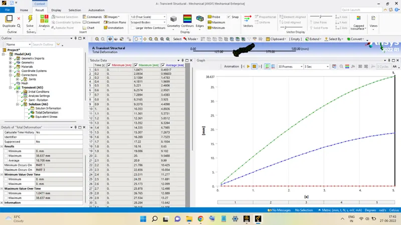
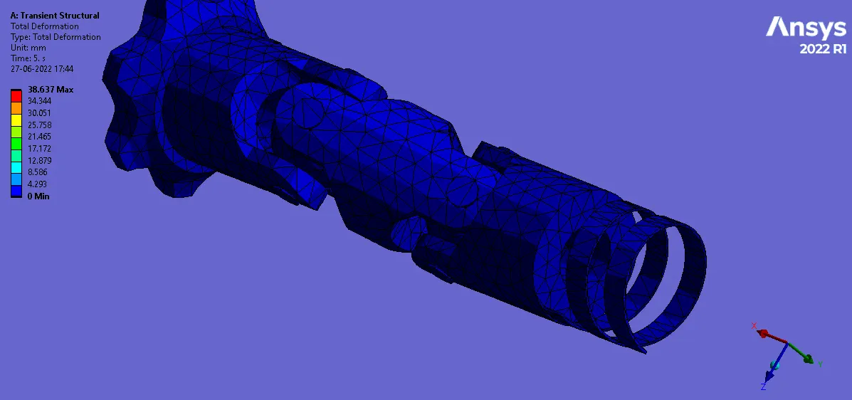
The above figures show the total deformation experienced by the model during the operation. The maximum deformation occurred in PART 3, equal to 38.637 mm.
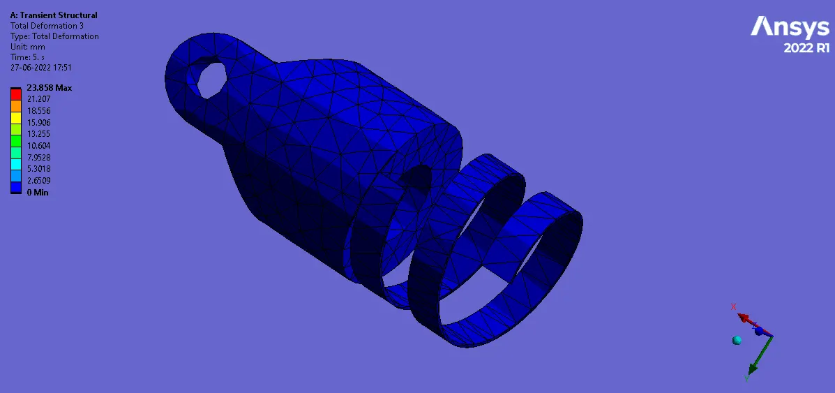
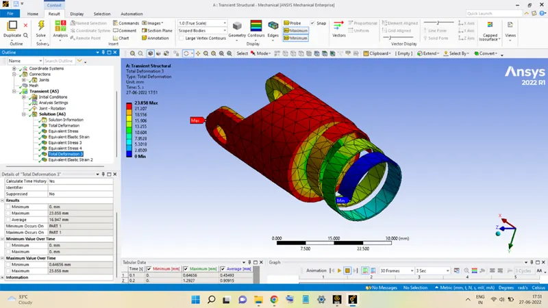
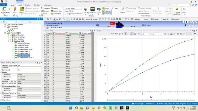
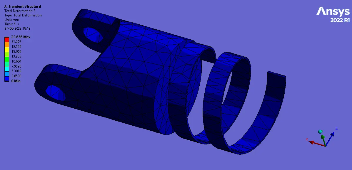
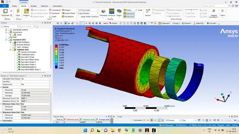
The deformation experienced by PART 1 is shown below, the maximum deformation in this part is equal to 23.858 mm.
CASE 2: STAINLESS STEEL
Equivalent Stress:
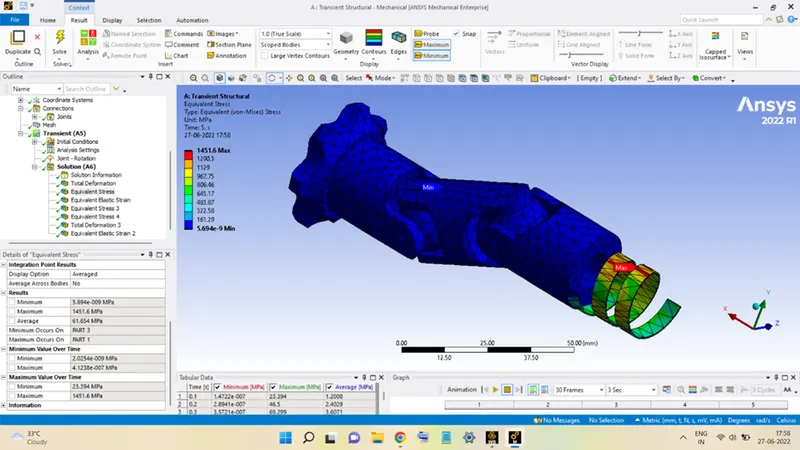
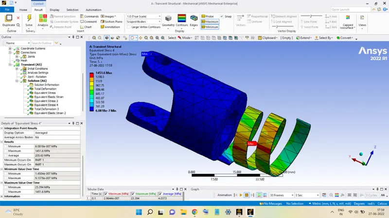
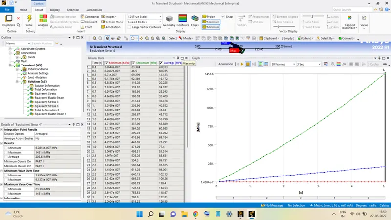
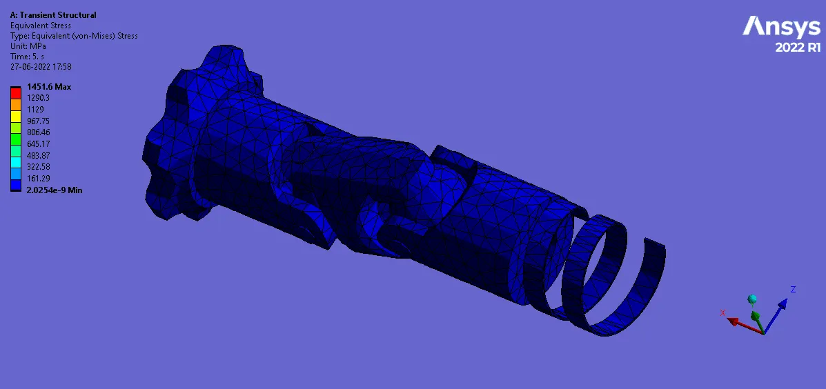
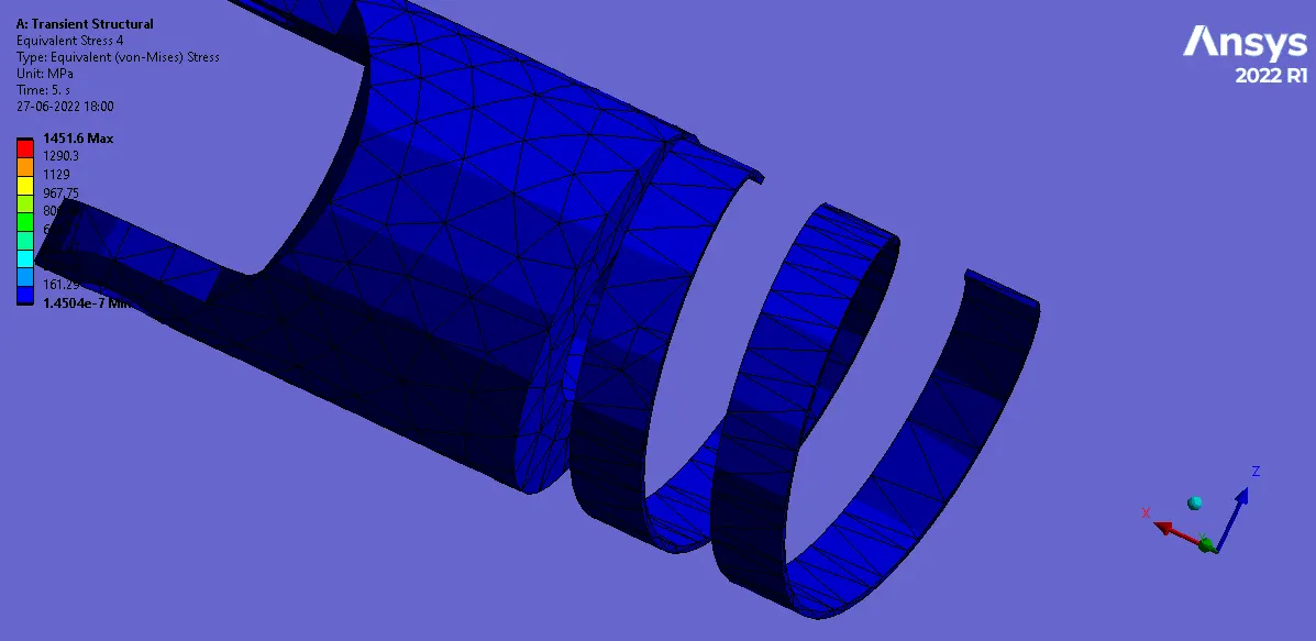
The stress developed in the model is shown in the above figures. The figure also shows the stress developed in PART 1. The maximum stress developed in the spring component, during the rotation is equal to 1451.6 MPa. The stress can be seen to be monotonically increasing in a somewhat linear fashion.
Total Deformation:
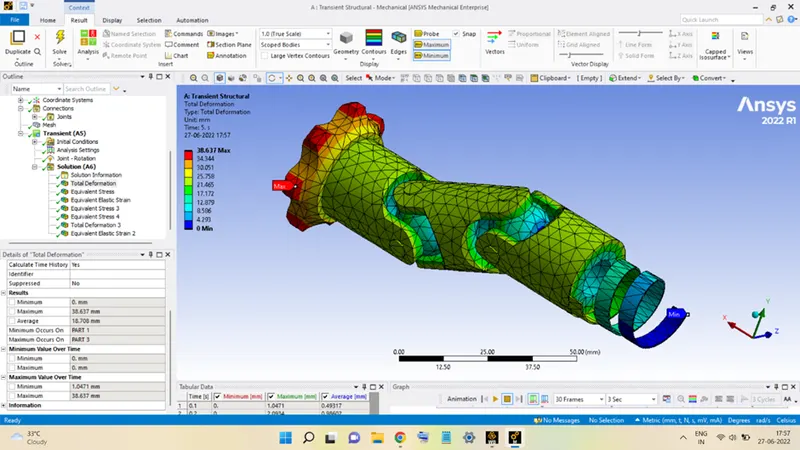
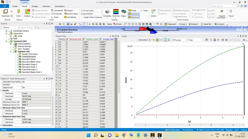
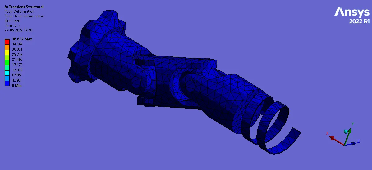
The above figures show the total deformation experienced by the model during the operation. The maximum deformation occurred in PART 3, equal to 38.637 mm.
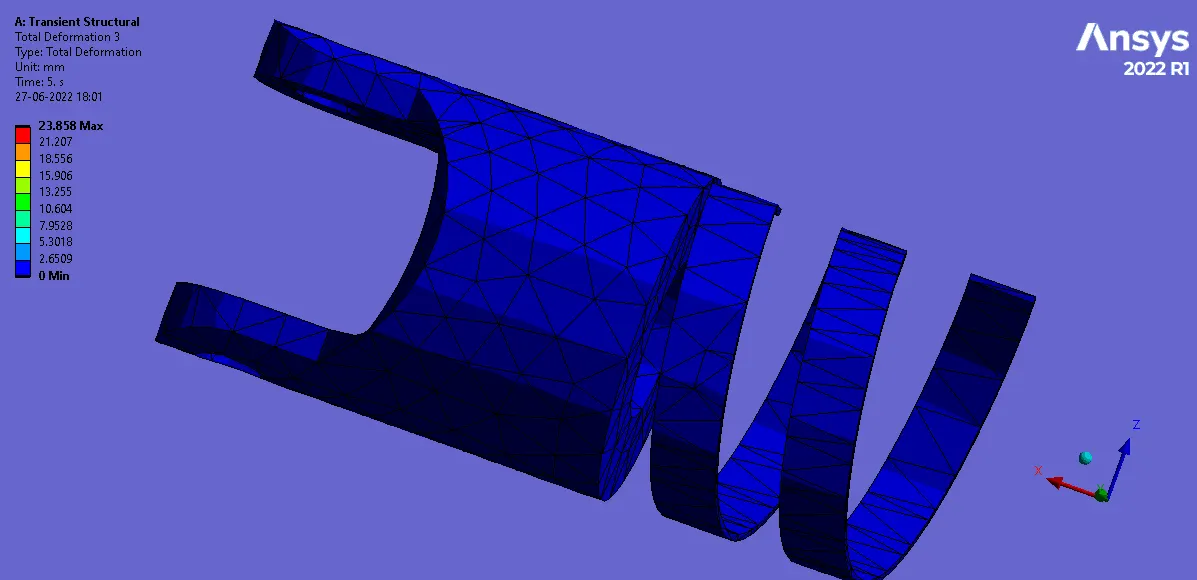
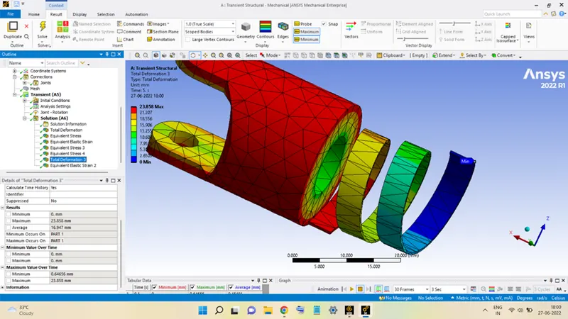
The deformation experienced by PART 1 is shown below, the maximum deformation in this part is equal to 23.858 mm.
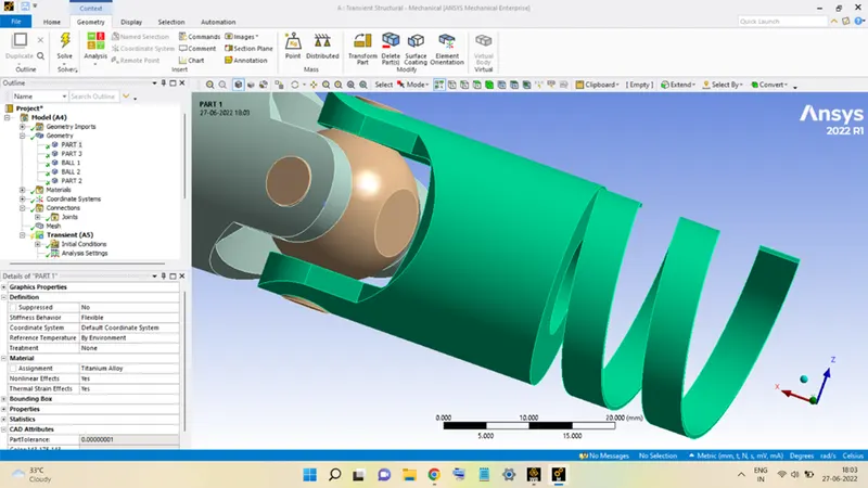
CASE 3: TITANIUM ALLOY
Equivalent Stress:
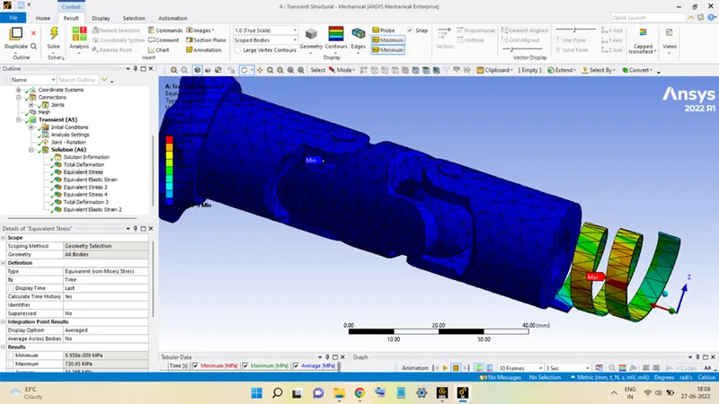
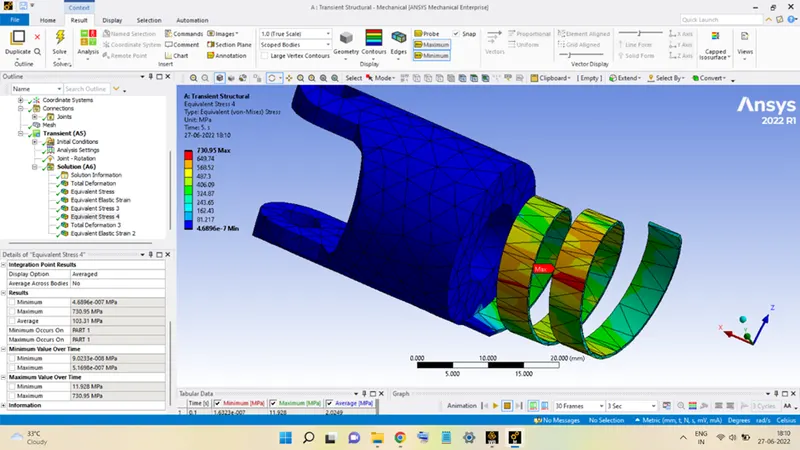
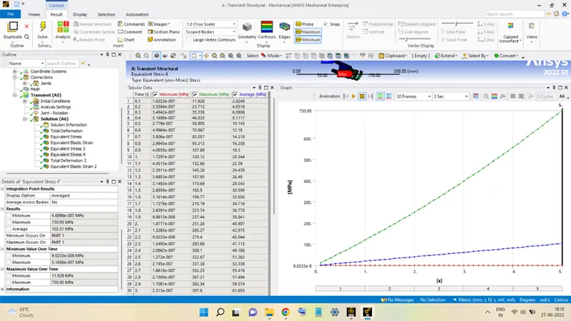
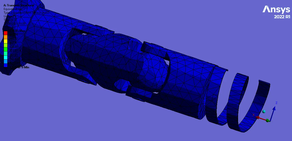
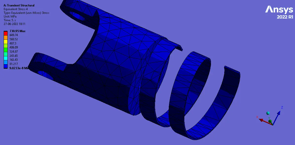
The stress developed in the model is shown in the above figures. The figure also shows the stress developed in PART 1. The maximum stress developed in the spring component, during the rotation is equal to 730.95 MPa. The stress can be seen to be monotonically increasing in a somewhat linear fashion.
Total Deformation:
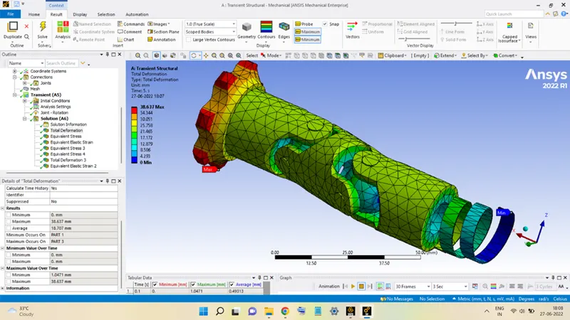
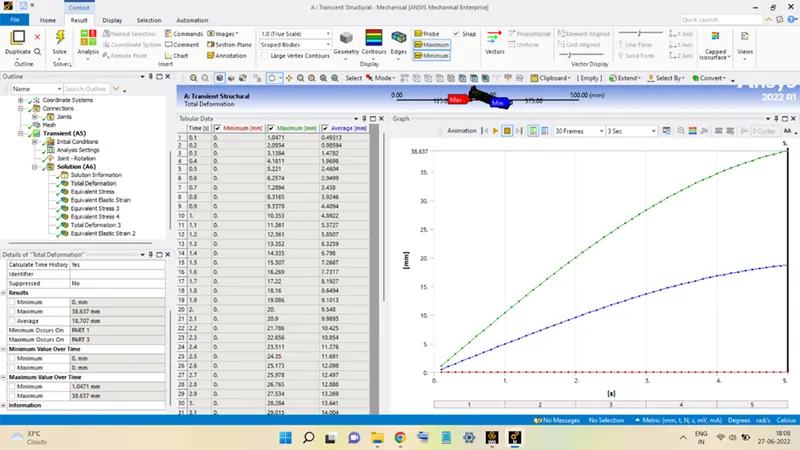
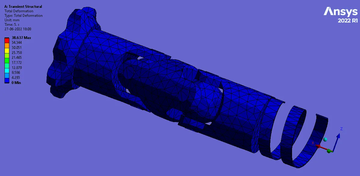
The above figures show the total deformation experienced by the model during the operation. The maximum deformation occurred in PART 3, equal to 38.637 mm.
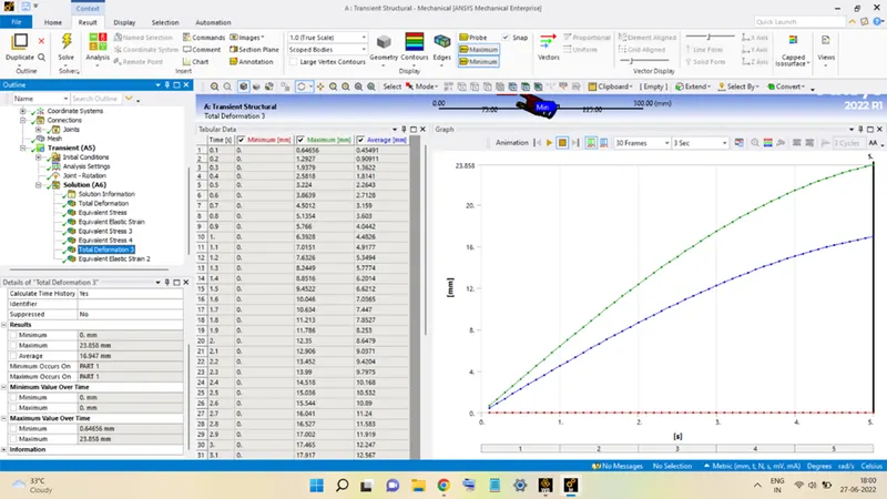
The deformation experienced by PART 1 is shown below, the maximum deformation in this part is equal to 23.858 mm.
Comparison:
|
|
MAX. STRESS (MPa) |
TOTAL DEFORMATION (mm) |
|
CASE 1: STRUCTURAL STEEL |
1502.1 |
23.858 |
|
CASE 2: STAINLESS STEEL |
1451.6 |
23.858 |
|
CASE 3: TITANIUM ALLOY |
730.95 |
23.858 |
The above table shows the results of PART 1 (Component with Spring) for three different cases. From the above table it can be said that:
For all the cases the deformation experienced by the component was the same.
For the same amount of deformation, the maximum stress values are highest for the Structural Steel component, followed by Stainless Steel, and then the Titanium Alloy with the lowest of all.
Since the maximum stress developed is least for the Titanium Alloy, it is the best pick out of the three because this material will give the highest values of the factor of Safety out of the three materials.