Week- 8 - Solid meshing
AIM :
To perform Solid meshing on the given components of the Rearview mirror model using ANSA Software.
OBJECTIVE:
- Import and clean up geometry using ANSA GUI.
- Check the CAD Topology and CAD Clean Up.
- Perform Shell meshing, Volumetric meshing & Tetrahedral meshing on different components as per quality criteria.
SOFTWARE TOOL USED :
ANSA Version 22.1.0
GIVEN DATA :
- CAD model.
- 2D Element Quality Criteria.
|
S.No |
Quality Criteria |
Value |
|
1 |
Target/Average length |
1 |
|
2 |
Minimum Length |
0.5 |
|
3 |
Maximum Length |
2 |
- Quality criteria after Volume meshing.
|
S.No |
Quality Criteria |
Value |
|
1 |
Tet collapse |
0.2 |
THEORY :
1. Quality Criteria :
Every product which is been produced will go through a set of quality checks. If the quality check fails other steps like boundary condition & applying loads will not be feasible, So for this reason the element quality check is performed. To identify the quality failure the quality criteria will be entered as input data. The elements should be maintained within the given quality criteria values. If the given quality value is not maintained there will be a failure in quality.
2. Geometry Clean-up :
Importing the model from other software to ANSA results in some geometrical deviations which need to be cleared before proceeding to other steps. In General chamfer/fillet faces, Unchecked faces, and average length errors occurred which is common while importing the model to ANSA from Modelling software. These errors must be cleared before any further operations. This clean-up will give the proper finish to the component and allow the engineer to work further with ease and accuracy.
3. Topological Activity :
Topology describes how the different faces and features of the geometry get connected with each other by forming CONS. There are 3 types of CONS which are SINGLE CON (Red), DOUBLE CON (yellow), and TRIPLE CON (Cyan Blue). Single cons mean that cons share only one surface, double cons are that cons share two surfaces, and triple cons are that which share three surfaces. Triple cons is a type of geometrical error because it shares three surfaces which cause geometry incompetency in the model so it is required to remove from geometry for topology cleanup. Before meshing the entire model must be of double cons, the rest all the single and triple cons must be removed for getting better results while doing analysis.
Boundary Cons of the faces and Features were called feature lines other Cons in the Model were called Construction Lines which were generated during the modeling of the component. Construction lines can be altered if one wants to get a better mesh flow. Feature lines should not be disturbed as it will result in a change in geometry however if the cons Length is less than the minimum element size it will result in element failure under such circumstances the feature line can be altered up to some extent without giving up the design feature of the part.
4. Orientation :
Orientation in ANSA is indicated by Grey or Yellow surfaces Grey surface usually acts as a positive direction and Yellow acts as a negative direction. The face is said to be inconsistent if one face has both Grey and Yellow Colours. The faces Orient option will fix this issue by changing one side of the face to be yellow in color and the other side to be Grey in color this will make the model consistent.
5. Meshing/Mesh generation :
Mesh generation is the process of discretizing the entire model into smaller elements in other words Mesh is a network that is formed of cells and points.
There are two types of meshing, 2D Mesh & 3D Mesh. In 2D Mesh, the mid surface is extracted from the component and then meshing is done on the mid surface whereas in 3D Mesh, direct meshing is done on the component from inside out. The difference between the 2D & 3D mesh is that the mesh type in 2D Mesh is mixed whereas in 3D Mesh the mesh type is Ortho tria ( for complex regions such as fillets and hemmings) or Tria ( For regions that are flat and not as complicated ).
7. Meshing flow and quality improvement :
In ANSA mesh can be generated easily but the mesh will have a lot of elements generated such that they fail to fulfill the Mesh Quality criteria also the mesh will have irregular elements which need to be eliminated. Mesh Flow and Mesh quality improvement are the most important steps in order to achieve good mesh quality and good Mesh Flow. To improve the mesh Quality there are many options available in ANSA, some of them are :
- Reconstruct
- Smooth
- Split, Swap, Join
- Changing Nodal numbers (Num+/-)
- Edge2Perimeter
Mesh is generated and the Mesh quality and the Mesh flow are improved using the above-said options for the entire model.
PROCEDURE :
Step 01 : Importing CAD Model.
- The initial step is to import the geometry into ANSA Software.
File -----> Open -----> Select the file -----> Open (Or we can drag and drop the file into ANSA)
Step 02 : Geometry cleanup
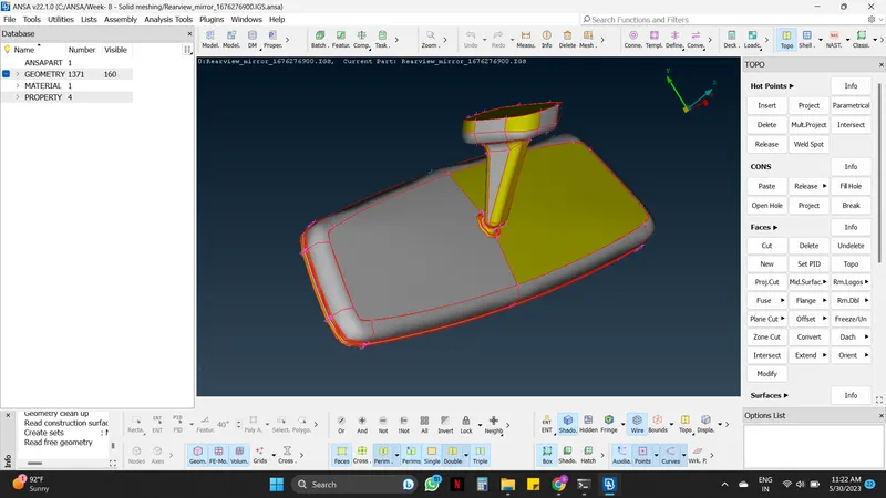
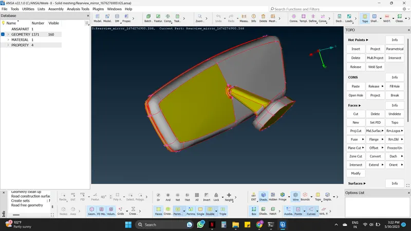
- The resolution of the cons must be done to check the actual shape of the cones in the geometry. There are two tools for that. One is the 'Fine' option in the Topo module under Auxiliaries. The other one is the 'Length' tool from the Mesh module under Perimeters. The 'Length' tool will help to do this in a single step when compared with the fine tool.
Mesh module -----> Perimeters -----> Length -----> Perimeter/macros (do this for both) -----> Select the whole surface -----> Middle mouse click -----> Give the value as 1 -----> Apply.
- After the resolution of the con, the TOPO operation is carried out to convert all single cons into double cons.
Topo module -----> Faces -----> Topo -----> Select the whole surface -----> Middle mouse click.
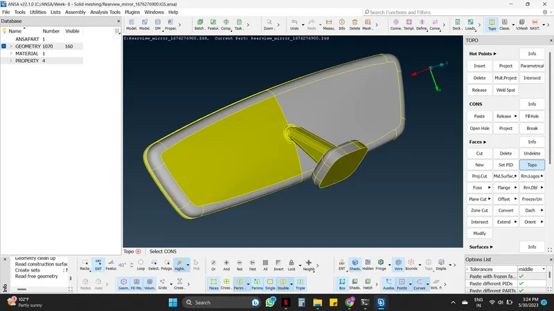
- It is observed that the given surface is with mixed yellow and grey color. This shows a mixed normal direction on the surface. So, to correct it as either yellow or grey on the outer surfaces to either gray(+ve) or yellow(-ve), preferably gray the tool, 'Orient' is used for this purpose.
Topo module -----> Faces -----> Orient -----> Choose select, Visible, and Auto appropriately.
If cons correction is done properly, choosing the visible option will change the color of entire surfaces in one go.
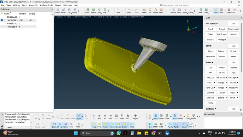
- After all the above operations the last step for the cleanup will be checking any geometrical errors and cleaning it.
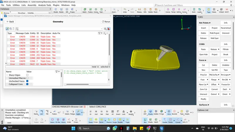
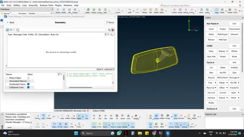
Tool tab -----> Check -----> Geometry -----> Execute -----> If any errors pop up in red color select them at once -----> Right mouse click -----> Fix -----> If not fixed, try manually -----> Then execute the geometry check again, it will show No errors or warning exist.
- Here in this component, there were some errors. Using the fix option all the errors got fixed.
Step 03 : Setting up the Quality Criteria and Mesh parameter
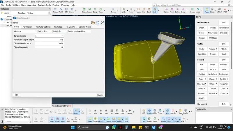
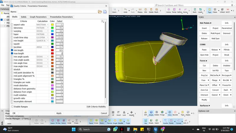
- Setting up the quality criteria as well as the mesh parameters is very important in every pre-processing process. This will make the mesh proper as per the requirements. Here the parameters are given, as per the given data fill the dialogue box, and apply to the component.
Utilities tab -----> Mesh Parameter -----> Set Element type: Ortho Tria, target length, minimum target length -----> Ok
Utilities tab -----> Quality Criteria -----> From the Shell tab set 2D element qualities as per the given values and from the solids tab set the 3D elements quality value -----> Ok
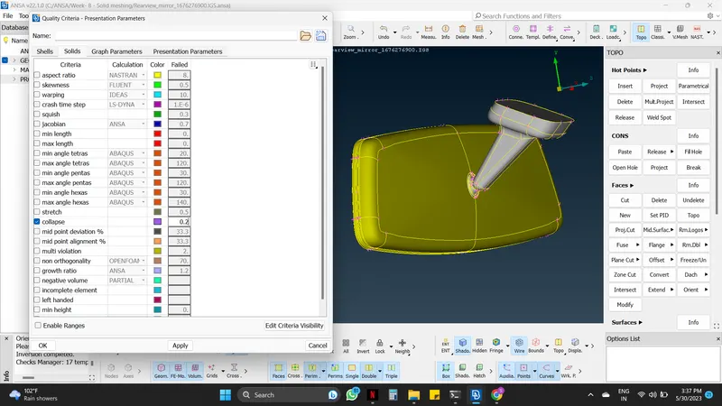
Step 04 : Meshing
- Generating the 3D mesh on the Rearview mirror component must be done using the spot mesh command.
Classic Mesh module -----> Mesh Generation -----> Spot Mesh -----> Select the surfaces -----> Apply (Middle mouse click).
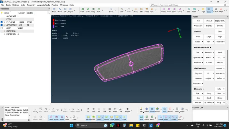
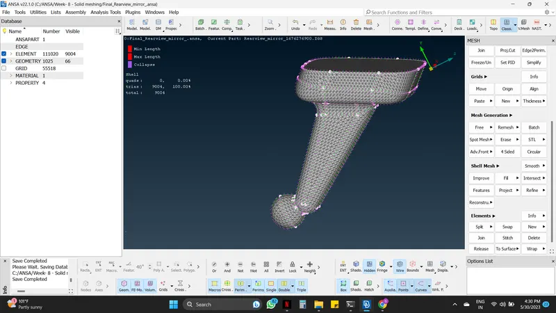
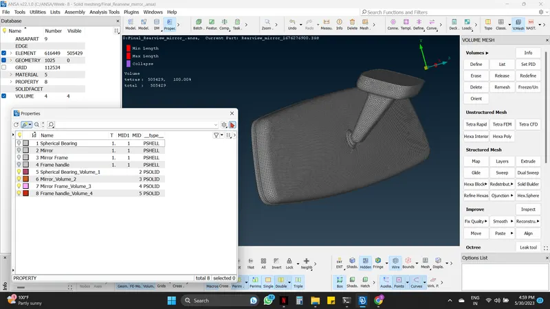
- Here Rearview Mirror is divided into four components and they are Spherical Bearing, Mirror, Mirror Frame, and Frame Handle. The properties are also given differently as shown in the below figure.
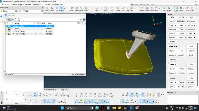
- Now perform the meshing on the components separately.
- For regions that are complex such as fillets and Hemmings, the element type must be Ortho Tria. As in mesh parameters element type is mentioned as ortho trias, here it will be auto-selected as ortho trias.
- For regions that are flat and not as complicated, the tria mesh must be used. The option to switch to tria is in the bottom right options section after selecting the spot mesh tool.
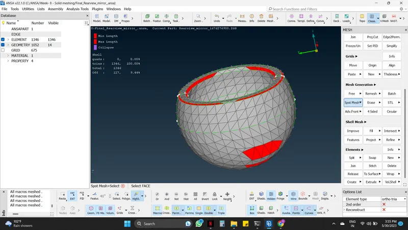
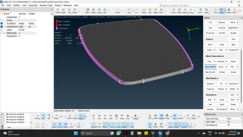
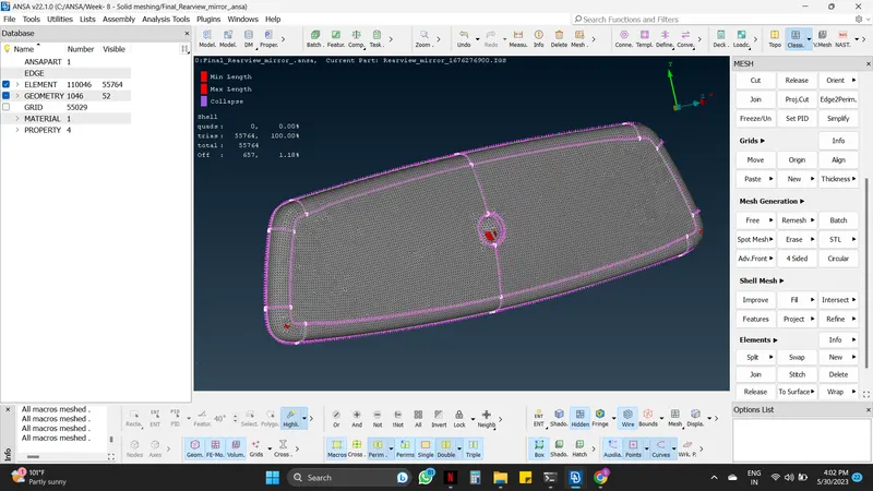
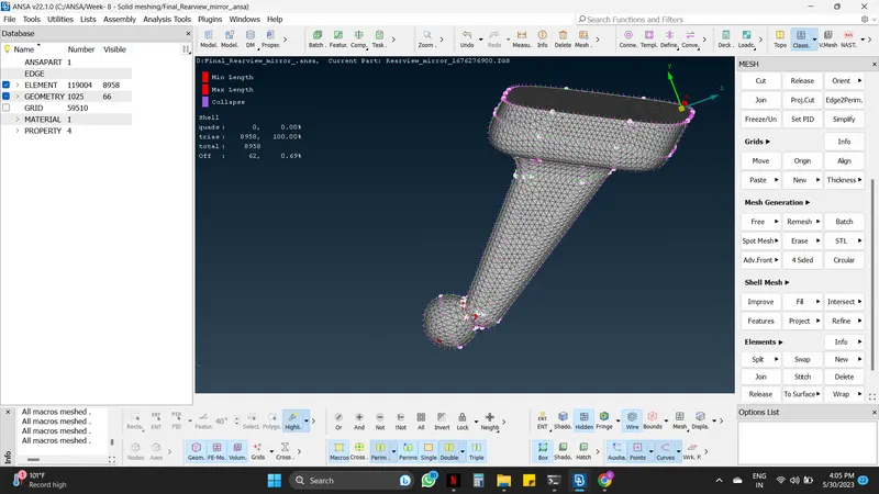
- After each Meshing iteration, there will be some errors that will not follow the quality criteria and will be seen in different colors. To make it proper and better mesh Reconstruct command must be used.
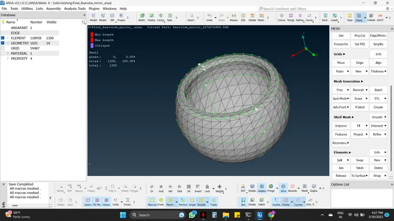
Reconstruct : Mesh module -----> Shell Mesh -----> Reconstruct.
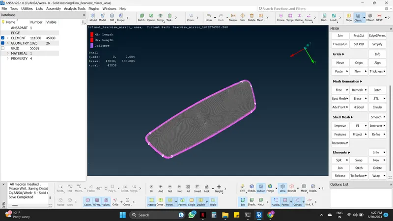
Step 05 : Volume Meshing Of The Model
- The meshing in the above step is done only on the outer side of the components, Now it's time to do the meshing from the inside and make the components from hollow to solid.
- For meshing from the inside and making the component solid Volume mesh must be used.
Volume Mesh module -----> Define -----> Detect on : Visible -----> Volume Dialogue box will appear which will have the property for the components (Auto detected) -----> Right Mouse click on the property and select Remesh.
- The below figs show the steps to volume mesh on the spherical bearing component.
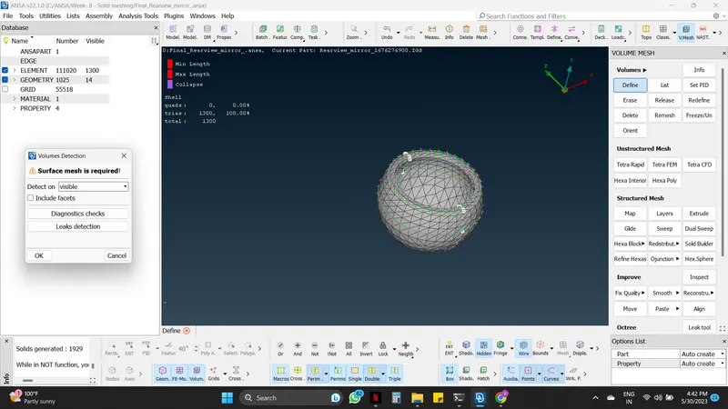
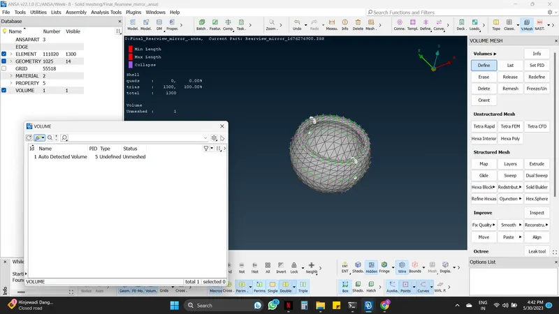
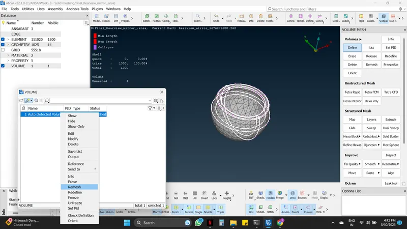
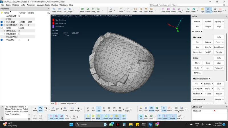
- Here solid meshed spherical bearing is obtained. By using a similar approach other components are also obtained.
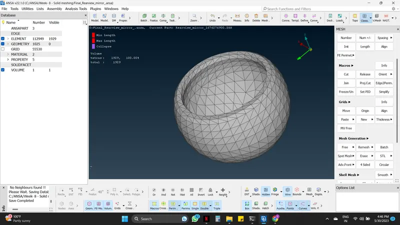
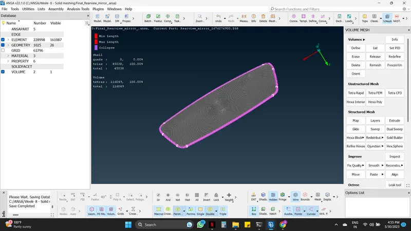
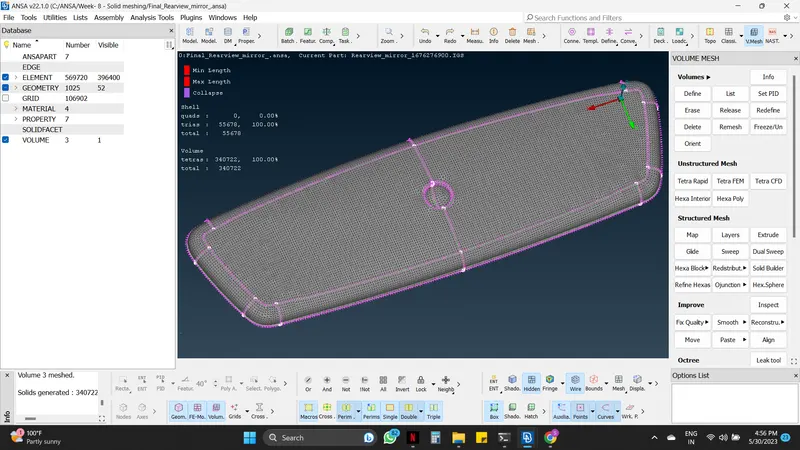
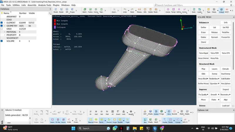
- Different components must have different properties as shown in fig below.
RESULTS :
Images of the final Rearview mirror component.
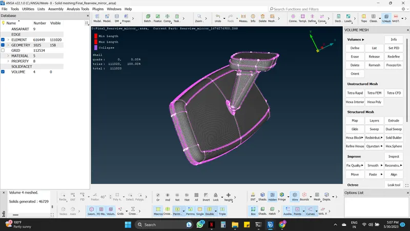
Fig. Spot mesh
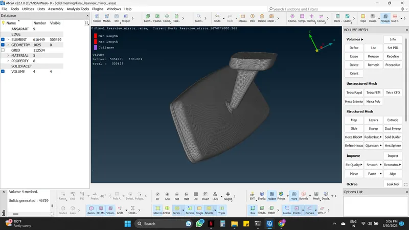
Fig. Volume mesh
LEARNING OUTCOMES :
By doing this challenge, the following aspects can be learned:
- Perform geometry cleanup for any complex 3D model.
- Generating the Mesh flow on the outside as well as on the inside of the model makes the model as solid.
- Familiarized with the ortho tria and tria mesh types through the spot mesh tool.
- Number of Total elements after volume mesh are significantly higher than the shell mesh
- Identify the quality failure and resolve the failure & improve the mesh quality.
- Work on ANSA with a flow.
CONCLUSION :
- The main part of the solid meshing is to combine both 'Ortho Tria' and 'Tria' elements as per the feature of the CAD model and to generate a better mesh flow to capture the CAD model precisely. The off elements in the surface shell mesh were also taken care of which failed for maximum and minimum quality criteria before going for the volume mesh which is another major step to follow.
- It was also noticed that the volume mesh can't be generated if the geometry is open. So the geometry has to be closed. Another important thing that has to be taken care of is the meshed surface should be without any kinks and dips after meshing which was achieved in here clearly the Tet collapse quality criteria.