Week 8 - Simulation of a backward facing step in OpenFOAM
:
To simulate an incompressible-laminar-viscous flow through the backward-facing step geometry and perform a transient simulation.
GIVEN SPECIFICATIONS:
Case 1 - Simulate the flow without using any grading factor (i.e., GF = 1)
Case 2 - Simulate the flow with a grading factor of 0.2. The cells should be finer near the walls (including the step wall).
Mesh specification
- cells along the x direction (longer dimension) = 200
- cells along with the longer y-direction = 20;
Boundary condition specification
The domain specifications are provided in the following figure.
Geometry Creation:
Let us consider creating the geometry using 5 blocks as shown in the figure below,
Vertices for each block by referring following sketch:
PROCEDURE :
- Open the terminal through ubuntu.
- Now we are going to simulate our problem in OpenFOAM and we are going to solve our problem using the tutorial file present in OpenFOAM. Type 'tut' to open the tutorial directory and then type 'ls' to see what kind of file is present inside the directory.
- We are going to solve for incompressible flow and so select an incompressible directory by typing 'cd' and then type 'ls' in order to explore files in the incompressible folder.
- In the incompressible folder, we see different types of solvers hence for this problem we need a solver for laminar viscous flow therefore here we choose 'icoFoam'.(icoFoam is a solver in OpenFOAM which is used as a transient solver for incompressible, laminar flow of Newtonian fluids. Therefore selecting this folder by typing 'cd icoFoam' and then using the 'ls' command for exploring the folder.
- Here we have two options cavity and elbow, they both are part of the icoFoam solver. Here we use the cavity folder for our required domain. But we are not going to make any changes here in the tutorial section, because OpenFOAM does not allow us to make any changes to their official tutorials.
- So we are going to copy the cavity folder using the 'cp-r cavity' command and paste it into the OpenFOAM run folder by typing 'cp-r cavity $FOAM_RUN/cavity_test'. Now we can make changes to this cavity_test folder which will never affect the OpenFOAM official file. Open cavity_test folder, here we can provide the specification for our block mesh in a system folder.
- There are 4 script file system folders and by opening blockMeshdict, we can create a domain and provide the specification for block mesh. So open this file by typing 'gedit blockMeshdict. Now make required changes in the blockMeshdict script file. First, in this file, we go to lines where hex word is found. These lines specify the faces of the blocks and the number of cells in the X, Y, and Z directions. Here there are 21 vertices and 5 blocks. Also, specify the faces as the inlet, outlet, and walls. Save and close this file.
- The next step is to navigate to the controlDict folder and specify simulation time. Then, we have to define initial values for velocity and pressure. In order to that, going back to the cavity_test folder and select the 'O' folder which stands for initial values. We set an initial boundary condition for pressure and velocity at each face and also update the name of the boundary same as we changed the inlet-outlet name in blockMeshdict.
- At this point, our problem statement is set, we can now proceed to deploy mesh using the 'blockmesh' command, and then we use the 'checkmesh' command to check whether there is an error. After deploying mesh, now we are ready to run our simulation.
- The simulation that we selected was 'icoFoam'. Hence just type 'icoFoam' and the simulation will start. Now, let us view the results in ParaView by using the 'paraFoam' command.
- Parafoam command takes us to the post processing process where we could visualize the results and see the variations.
CASE 1 : Simulation for the grading factor 1
1. BlockMeshDict
/*--------------------------------*- C++ -*----------------------------------*\
  =========                 |
  \\      /  F ield         | OpenFOAM: The Open Source CFD Toolbox
   \\    /   O peration     | Website:  https://openfoam.org
    \\  /    A nd           | Version:  8
     \\/     M anipulation  |
\*---------------------------------------------------------------------------*/
FoamFile
{
    version     2.0;
    format      ascii;
    class       dictionary;
    object      blockMeshDict;
}
// * * * * * * * * * * * * * * * * * * * * * * * * * * * * * * * * * * * * * //

convertToMeters 0.01;

vertices
(
    (0 0 0)
    (8 0 0)
    (8 0.5 0)
    (0 0.5 0)
    (8 1 0)
    (0 1 0)
    (20 1 0)
    (20 0.5 0)
    (20 0 0)
    (20 -1 0)
    (8 -1 0)
    (0 0 0.1)
    (8 0 0.1)
    (8 0.5 0.1)
    (0 0.5 0.1)
    (8 1 0.1)
    (0 1 0.1)
    (20 1 0.1)
    (20 0.5 0.1)
    (20 0 0.1)
    (20 -1 0.1)
    (8 -1 0.1)
);

blocks
(
    hex (0 1 2 3 11 12 13 14) (80 5 1) simpleGrading (1 1 1)
    hex (3 2 4 5 14 13 15 16) (80 5 1) simpleGrading (1 1 1)
    hex (2 7 6 4 13 18 17 15) (120 5 1) simpleGrading (1 1 1)
    hex (1 8 7 2 12 19 18 13) (120 5 1) simpleGrading (1 1 1)
    hex (10 9 8 1 21 20 19 12) (120 10 1) simpleGrading (1 1 1)
);

edges
(
);

boundary
(
    inlet
    {
        type patch;
        faces
        (
            (0 11 14 3)
            (3 14 16 5)
        );
    }
    outlet
    {
        type patch;
        faces
        (
            (9 8 19 20)
            (8 7 18 19)
            (7 6 17 18)
        );
    }
    frontAndBack
    {
        type empty;
        faces
        (
            (0 3 2 1)
            (3 5 4 2)
            (2 4 6 7)
            (1 2 7 8)
            (10 1 8 9)
            (11 12 13 14)
            (14 13 15 16)
            (13 18 17 15)
            (12 19 18 13)
            (21 20 19 12)
        );
    }
    Noslipwalls
    {
        type wall;
        faces
        (
            (5 16 15 4)
            (4 15 17 6)
            (0 1 12 11)
            (10 21 12 1)
            (10 9 20 21)

        );
    }
);

mergePatchPairs
(
);

// ************************************************************************* //
1. The vertices of our splitted block should be defined in the code.
2. Here we splitted the model into five blocks having eight vertices each.
3. And the blocks should be defined with its respective vertices.
4. Also the number of cells in the x and y direction should be defined and here we are defining 200 cells in x and 20 in y direction.
5. And the first case is of grading factor 1 and so the mesh will be even in all directions.
6. "blockMeshDict" command will be used to mesh the model.
7. And it can be viewed through the post processing tool, "paraFoam".
2. ControlDict
/*--------------------------------*- C++ -*----------------------------------*\
  =========                 |
  \\      /  F ield         | OpenFOAM: The Open Source CFD Toolbox
   \\    /   O peration     | Website:  https://openfoam.org
    \\  /    A nd           | Version:  8
     \\/     M anipulation  |
\*---------------------------------------------------------------------------*/
FoamFile
{
    version     2.0;
    format      ascii;
    class       dictionary;
    location    "system";
    object      controlDict;
}
// * * * * * * * * * * * * * * * * * * * * * * * * * * * * * * * * * * * * * //

application     icoFoam;

startFrom       startTime;

startTime       0;

stopAt          endTime;

endTime         0.5;

deltaT          0.0001;

writeControl    timeStep;

writeInterval   20;

purgeWrite      0;

writeFormat     ascii;

writePrecision  6;

writeCompression off;

timeFormat      general;

timePrecision   6;

runTimeModifiable true;


// ************************************************************************* //
1. The controlDict has the numerical schemes which needs to be used for the simulation.
2. And the start and end time should be included in the code.
3. Setting the initial profiles for U and p
Initial setup for pressure:
/*--------------------------------*- C++ -*----------------------------------*\
  =========                 |
  \\      /  F ield         | OpenFOAM: The Open Source CFD Toolbox
   \\    /   O peration     | Website:  https://openfoam.org
    \\  /    A nd           | Version:  8
     \\/     M anipulation  |
\*---------------------------------------------------------------------------*/
FoamFile
{
    version     2.0;
    format      ascii;
    class       volScalarField;
    object      p;
}
// * * * * * * * * * * * * * * * * * * * * * * * * * * * * * * * * * * * * * //

dimensions      [0 2 -2 0 0 0 0];

internalField   uniform 0;

boundaryField
{
    inlet
    {
        type            zeroGradient;
    }

    outlet
    {
        type            fixedValue;
        value           uniform 0;
    }
    Noslipwalls
    {
    type               zeroGradient;
    }

    frontAndBack
    {
        type            empty;
    }
}

// ************************************************************************* //
Initial Setup for Velocity:
/*--------------------------------*- C++ -*----------------------------------*\
  =========                 |
  \\      /  F ield         | OpenFOAM: The Open Source CFD Toolbox
   \\    /   O peration     | Website:  https://openfoam.org
    \\  /    A nd           | Version:  8
     \\/     M anipulation  |
\*---------------------------------------------------------------------------*/
FoamFile
{
    version     2.0;
    format      ascii;
    class       volVectorField;
    object      U;
}
// * * * * * * * * * * * * * * * * * * * * * * * * * * * * * * * * * * * * * //

dimensions      [0 1 -1 0 0 0 0];
internalField   uniform (0.15 0 0);

boundaryField
{
    inlet
    {
        type            fixedValue;
        value           uniform (0.15 0 0);

    }

    outlet
    {
        type            zeroGradient;
    }

    Noslipwalls
    {
       type             noSlip;
    }

    frontAndBack
    {
        type            empty;
    }
}

// ************************************************************************* //
RESULTS:
Meshing using blockmesh for the simple grading factor 1,
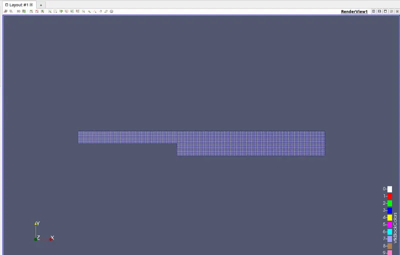
> The mesh is based on the grading factor which is of value 1 and so the mesh will be of same size and even throughout the model.
SIMULATION RESULTS:
VELOCITY CONTOUR:
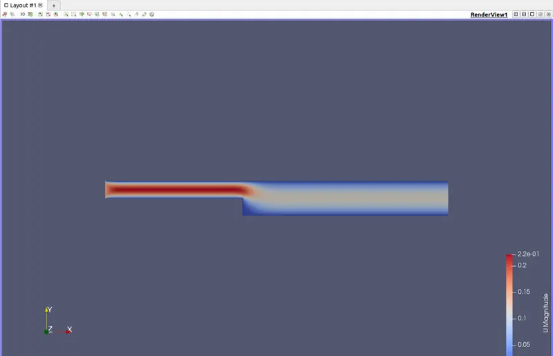
The above contour shows the velocity field which is flowing through the backward facing step.
PRESSURE CONTOUR:
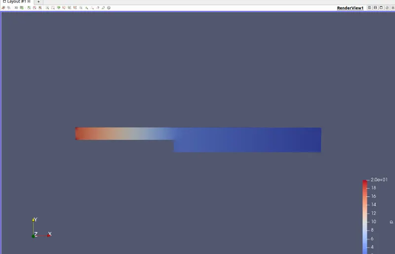
The above contour is of pressure field over the model.
VELOCITY PROFILE:
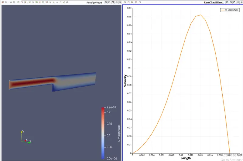
The velocity profile is shown at the position x = 0.085m, where the velocity is varying in such fashion!
PRESSURE PROFILE:
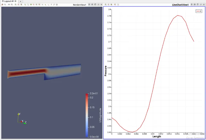
The above profile gives the pressure change at the point x = 0.085m.
CASE 2 : Simulation for the grading factor 0.2
1. BlockMeshDict
/*--------------------------------*- C++ -*----------------------------------*\
  =========                 |
  \\      /  F ield         | OpenFOAM: The Open Source CFD Toolbox
   \\    /   O peration     | Website:  https://openfoam.org
    \\  /    A nd           | Version:  8
     \\/     M anipulation  |
\*---------------------------------------------------------------------------*/
FoamFile
{
    version     2.0;
    format      ascii;
    class       dictionary;
    object      blockMeshDict;
}
// * * * * * * * * * * * * * * * * * * * * * * * * * * * * * * * * * * * * * //

convertToMeters 0.01;

vertices
(
    (0 0 0)
    (8 0 0)
    (8 0.5 0)
    (0 0.5 0)
    (8 1 0)
    (0 1 0)
    (20 1 0)
    (20 0.5 0)
    (20 0 0)
    (20 -1 0)
    (8 -1 0)
    (0 0 0.1)
    (8 0 0.1)
    (8 0.5 0.1)
    (0 0.5 0.1)
    (8 1 0.1)
    (0 1 0.1)
    (20 1 0.1)
    (20 0.5 0.1)
    (20 0 0.1)
    (20 -1 0.1)
    (8 -1 0.1)
);

blocks
(
    hex (0 1 2 3 11 12 13 14) (80 5 1) simpleGrading (1 5 1)
    hex (3 2 4 5 14 13 15 16) (80 5 1) simpleGrading (1 0.2 1)
    hex (2 7 6 4 13 18 17 15) (120 5 1) simpleGrading (5 0.2 1)
    hex (1 8 7 2 12 19 18 13) (120 5 1) simpleGrading (5 5 1)
    hex (10 9 8 1 21 20 19 12) (120 10 1) simpleGrading (5 5 1)
);

edges
(
);

boundary
(
    inlet
    {
        type patch;
        faces
        (
            (0 11 14 3)
            (3 14 16 5)
        );
    }
    outlet
    {
        type patch;
        faces
        (
            (9 8 19 20)
            (8 7 18 19)
            (7 6 17 18)
        );
    }
    frontAndBack
    {
        type empty;
        faces
        (
            (0 3 2 1)
            (3 5 4 2)
            (2 4 6 7)
            (1 2 7 8)
            (10 1 8 9)
            (11 12 13 14)
            (14 13 15 16)
            (13 18 17 15)
            (12 19 18 13)
            (21 20 19 12)
        );
    }
    Noslipwalls
    {
        type wall;
        faces
        (
            (5 16 15 4)
            (4 15 17 6)
            (0 1 12 11)
            (10 21 12 1)
            (10 9 20 21)

        );
    }
);

mergePatchPairs
(
);

// ************************************************************************* //
1. The vertices of our splitted block should be defined in the code.
2. Here we splitted the model into five blocks having eight vertices each.
3. And the blocks should be defined with its respective vertices.
4. Also the number of cells in the x and y direction should be defined and here we are defining 200 cells in x and 20 in y direction.
5. And the first case is of grading factor 0.2 and so the mesh will not be even in all directions.
6. Grading in mesh will helps us to vary the number of grids or elements where it will be easy to capture the values.
7. "blockMeshDict" command will be used to mesh the model.
8. And it can be viewed through the post processing tool, "paraFoam".
2. ControlDict
/*--------------------------------*- C++ -*----------------------------------*\
  =========                 |
  \\      /  F ield         | OpenFOAM: The Open Source CFD Toolbox
   \\    /   O peration     | Website:  https://openfoam.org
    \\  /    A nd           | Version:  8
     \\/     M anipulation  |
\*---------------------------------------------------------------------------*/
FoamFile
{
    version     2.0;
    format      ascii;
    class       dictionary;
    location    "system";
    object      controlDict;
}
// * * * * * * * * * * * * * * * * * * * * * * * * * * * * * * * * * * * * * //

application     icoFoam;

startFrom       startTime;

startTime       0;

stopAt          endTime;

endTime         0.5;

deltaT          0.0001;

writeControl    timeStep;

writeInterval   20;

purgeWrite      0;

writeFormat     ascii;

writePrecision  6;

writeCompression off;

timeFormat      general;

timePrecision   6;

runTimeModifiable true;


// ************************************************************************* //
RESULTS:
Mesh created for the grading factor 0.2
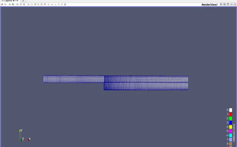
> The mesh is based on the grading factor which is of value 0.2 and so the mesh will be of same size and even throughout the model.
SIMULATION PLOTS:
VELOCITY CONTOUR:
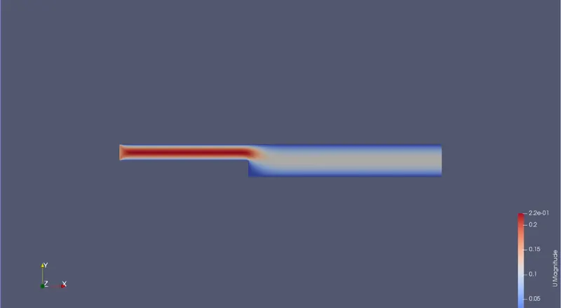
The above contour shows the velocity field which is flowing through the backward facing step.
PRESSURE CONTOUR:
The above contour is of pressure field over the model.
VELOCITY PROFILE:
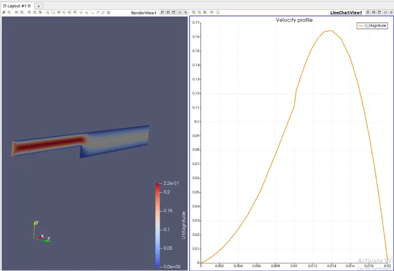
The velocity profile is shown at the position x = 0.085m, where the velocity is varying in such fashion!
PRESSURE PROFILE:
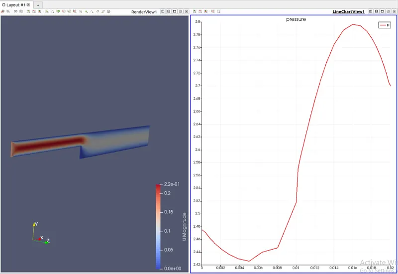
The above profile gives the pressure change at the point x = 0.085m.
CONCLUSION:
1. The results are based on the meshing and the grading factor.
2. Varying the mesh quality and the grading factor will have a straight impact on the velocity and the pressure.