Week 8 - Simulating Cyclone separator with Discrete Phase Modelling
Aim:- To perform analysis on cyclone separator and calculate the separation efficiency and pressure drop.
Objective:-
- To write a few words about any four empirical models used to calculate the cyclone separator efficiency.
- To perform an analysis on a given cyclone separator model by varying the particle diameter from 1 μm to 5 μm and calculate the separation efficiency in each case. Discuss the results. [Use both the velocity's as 3m/sec.]
- To perform an analysis on a given cyclone separator model by varying the particle velocity from 1 m/sec to 5 m/sec and calculate the separation efficiency and pressure drop in each case. Discuss the results. [Use particle diameter size as 5 μm for all cases & keep flow velocity same as particle velocity]
Boundary Conditions:-
Inlet and wall:- Reflect
Outlet(Top):- Escape
Outlet(Bottom/dustbin) - Trap
Introduction:
Cyclone separators are separation devices based on the principle of inertia to remove particulate matter from the flue gases. It works based on the centrifugal action wherein a continuous feed of impure air into the chamber subjected to spiral vortex formation separating the particles from fluid. The lighter components of the gas have less inertia, influenced by vortex and move towards upper direction. The inertia force of gas particle flows to a centrifugal force by means of a vortex generated in the cyclone body. The particle laden air stream enters tangentially at the top of the barrel and travels downward into the cone forming an outer vortex. The increase in air velocity in the outer side of vertex results in centrifugal force on the particles separating them from the air stream. The particles fall into the dust collection chamber at the bottom and clean air comes out the top. The efficiency of the cyclone collector depends on the pressure drop which is the function of inlet velocity and cyclone diameter across the collector.
Cyclone separator efficiency can be calculated by the empirical models discussed below:
|
Lozia and Leith Model-Iozia and Leith (1990) model It is a logistic model modified version of Barth (1956) model. It was developed based on force balance assuming that a particle carried by the vortex endures the influence of two forces: a centrifugal force, Z, and a flow resistance, W. |
|
Lapple Model-Lapple (1951) model This model was developed based on force balance without considering the flow resistance. In this the case the assumption is that the particle entering the cyclone is evenly distributed across the inlet opening. The particle that travels from inlet half width to the wall in the cyclone is collected with 50% efficiency. |
|
Koch & Licht Model-Koch and Licht (1977) model This model is a collection theory recognized inherently turbulent nature of cyclones and the distribution of gas residence times within the cyclone. Koch and Licht describe particle motion in the entry and collection regions with the additional assumptions namely: The tangential velocity of a particle is equal to the tangential velocity of the gas flow, i.e. there is no slip in the tangential direction between the particle and the gas. |
|
Li and Wang Model-The Li and Wang (1989) model This model includes particle bounce or re-entrainment and turbulent diffusion at the cyclone wall. A 2D analytical expression of particle distribution in the cyclone is obtained. Li and Wang model was developed based on the following assumptions: The radial particle velocity and the radial concentration profile are not constant, for uncollected particles within the cyclones. |
- Geometry preparation
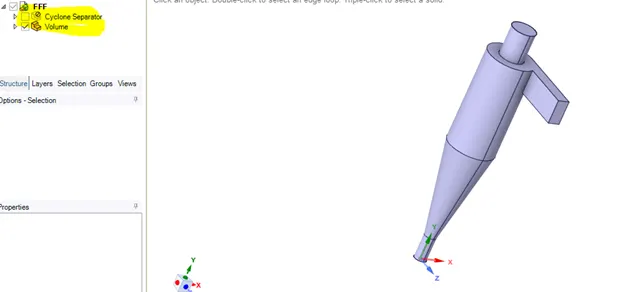
- IMPORT GEOMETRY IN SPACE CLAIM--> PREPARE --> VOLUME EXTRACTION --> SELECT EDGES --> CLICK TICK. THEN In STRUCTURE > OUTER SOLID > UNSELECT --> SUPPRESS FOR PHYSICS --> CLOSE GEOMETRY
- Mesh
- OPEN MESH -->ENTITY SELECTION > FACE SELECTION--> select the faces of the geometry to be mentioned as boundaries NAMELY INLET & OUTLET
- MESH -- > GENERATE MESH.
- QUALITY --> MESH METRIC --> ELEMENT QUALITY --> C GRAPH ( AS LONG AS ELEMENT QUANTITY is not lower than 5%, SIMULAION RUNS)
- Close the Mesh
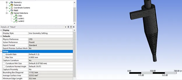
- Cutcell meshing approach is followed for this problem to get finest mesh.
- Mesh Size
- Set Up
- DOUBLE CLICK SETUP -- > FLUENT LAUNCHER -->DOUBLE PRECISION.
- Ansys Fluent is opened.
- In Graphics window --> GEOMETRY AND CONSOLE window is displayed.
- SETTING UP DOMAIN -->MESH --> select CHECK. Then in CONSOLE WINDOW --> it shows 'CHECKING MESH…. DONE'
- To Change the Units, SETTING UP DOMAIN --> click Units
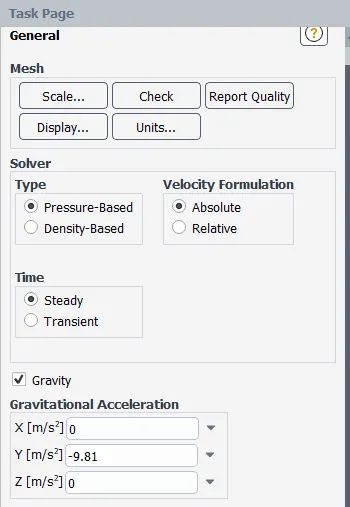
- SETTING UP PHYSICS --> SOLVER --> select Time = STEADY, Type = PRESSURE BASED & Velocity Formation = ABSOLUTE.
- Here Gravity is in opposite direction i.e. y=-9.81.
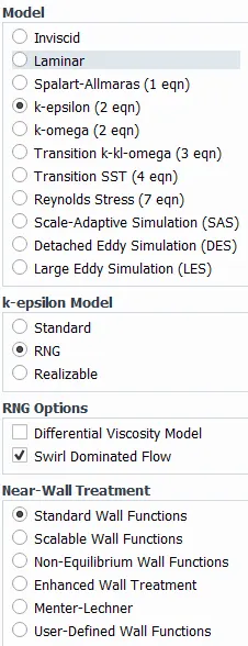
- SETTING UP PHYSICS --> K-epsilon Model, RNG, by selecting Swirl Domination Flow and with standard wall functions.
- Discrete Phase -->select Interaction and check the tracking parameters. Click InjectionsàCreate injection properties.
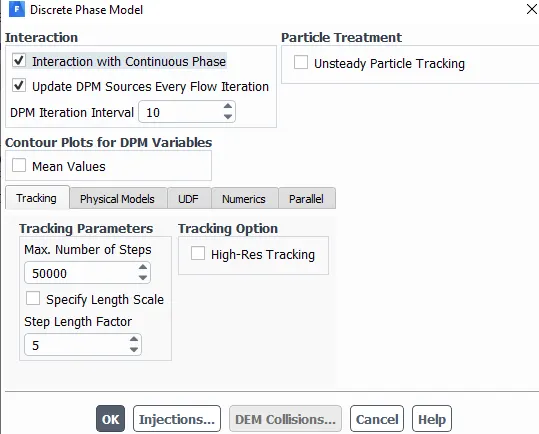
- injection properties --> select injection type=surface
- Release from surfaces=inlet, select material=anthracite with uniform distribution.
- Go to point properties --> set the variable diameter,velocity magnitude--> Ok to generate Injection. Close Discrete Phase Model.
- Boundaries-->set-->Inlet and wall= Reflect, Outlet(Top)=Escape, Outlet(Bottom)=Trap for all the cases. Set the velocity of the fluid
- Solution
- Scheme=SIMPLE, spatial Discretization=Least square Cell Based, Pressure=standard, Momentum= First order upwind, Turbulence= First order upwind, Turbulent Dissipation Rate= First order upwind.
- INITIALIZATION --> select METHOD = STANDARD --> select compute from=INLET and then initialize the solution.
- RUN CALCULATION --> NO. OF ITERATIONS =400 and press CALCULATE.
- Results and Discussion:
- Double click on RESULTS --> Post process window opens
| Case1 : Vary particle diameter from 1 μm to 5 μm and keep flow velocity same as particle velocity = 3m/s |
| Particle velocity (m/s) | Flow velocity (m/s) | Particle diameter size (µm) | Particles tracked | Particles escaped | Particles trapped | Particle incomplete | Cyclone separator efficiency (%) |
| 3 | 3 | 1 | 98 | 62 | 36 | 0 | 0.367346939 |
| 3 | 3 | 2 | 98 | 59 | 39 | 0 | 0.397959184 |
| 3 | 3 | 3 | 98 | 56 | 42 | 0 | 0.428571429 |
| 3 | 3 | 4 | 98 | 47 | 51 | 0 | 0.520408163 |
| 3 | 3 | 5 | 98 | 41 | 57 | 0 | 0.581632653 |
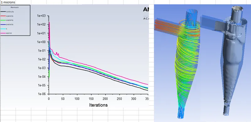
Case-1 (particle diameter =1 μm)
Residuals , Anthracite Particle Time Contour & Vortex core region:
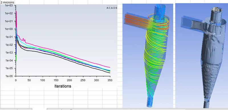
Case-1 (particle diameter =2 μm)
Residuals , Anthracite Particle Time Contour & Vortex core region:
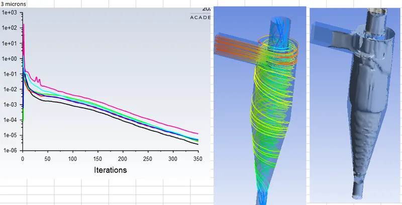
Case-1 (particle diameter =3 μm)
Residuals , Anthracite Particle Time Contour & Vortex core region:
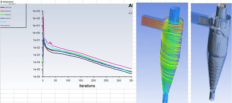
Case-1 (particle diameter =4 μm)
Residuals , Anthracite Particle Time Contour & Vortex core region:
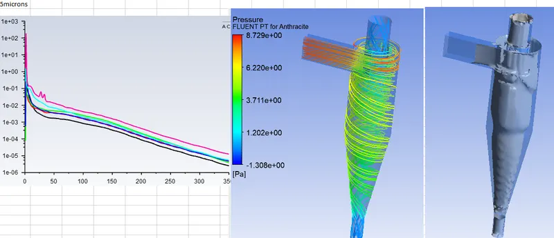
Case-1 (particle diameter =5 μm)
Residuals , Anthracite Particle Time Contour & Vortex core region:
Inference: The following inferences were drawn:
- Simulated for the range of particle size from 1µ to 5µ keeping the velocity of both flow velocity and particle velocity as 3m/s.
- Fine mesh, has resulted in no incomplete particles in all the cases and more accurate and high efficiency of the cyclone seperator
- From the case table, increasing the particle size resulted in decrease in escaped particles and increase in trapped particles.
- Increasing the particle size --> the separation efficiency also increased. The separation efficiency is given by (number of trapped particles) / (number of tracked particles)
Case 2 : Vary particle velocity from 1 m/sec to 5 m/sec and keep particle diameter size as 5 μm for all cases & flow velocity same as particle velocity
| Particle velocity (m/s) | Flow velocity (m/s) | Particle diameter size (µm) | Particles tracked | Particles escaped | Particles trapped | Particle incomplete | Cyclone separator efficiency (%) | Min Pressure (Pa) | Max Pressure (Pa) | dP |
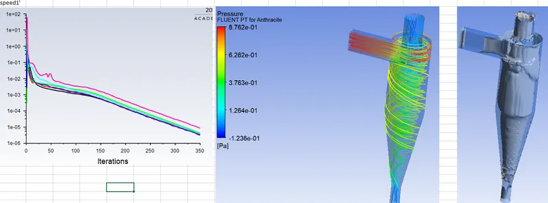
| 1 | 1 | 5 | 98 | 57 | 27 | 14 | 0.275510204 | -1.236 | 0.8762 | 2.1122 |
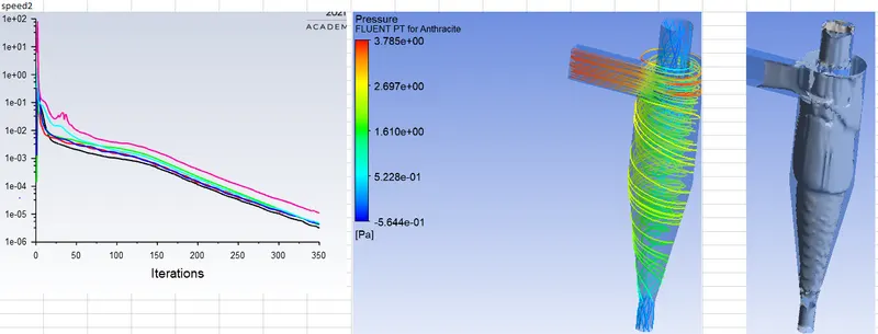
| 2 | 2 | 5 | 98 | 47 | 51 | 0 | 0.520408163 | -0.564 | 3.7846 | 4.3486 |
| 3 | 3 | 5 | 98 | 41 | 57 | 0 | 0.581632653 | -1.31 | 8.729 | 10.039 |
| 4 | 4 | 5 | 98 | 39 | 59 | 0 | 0.602040816 | -2.36 | 15.72 | 18.08 |
| 5 | 5 | 5 | 98 | 33 | 65 | 0 | 0.663265306 |
Case-2 (Velocity = 1m/s)
Residuals , Anthracite Particle Time Contour & Vortex core region:
Case-2 (Velocity = 2m/s)
Residuals , Anthracite Particle Time Contour & Vortex core region:
https://youtu.be/XUHfbb9J5s8
Case-3 (Velocity = 3m/s)
Residuals , Anthracite Particle Time Contour & Vortex core region:
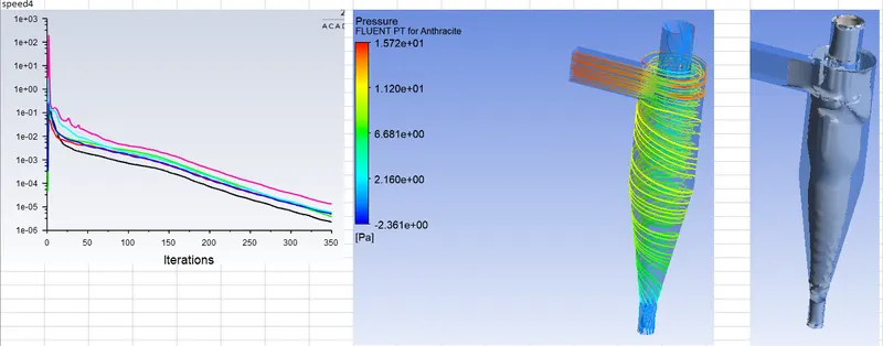
Case-4 (Velocity = 4m/s)
Residuals , Anthracite Particle Time Contour & Vortex core region:
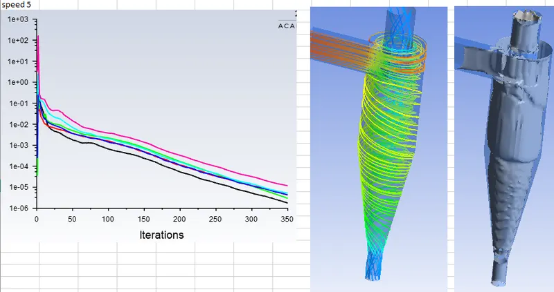
Case-5 (Velocity = 5m/s)
Residuals , Anthracite Particle Time Contour & Vortex core region:
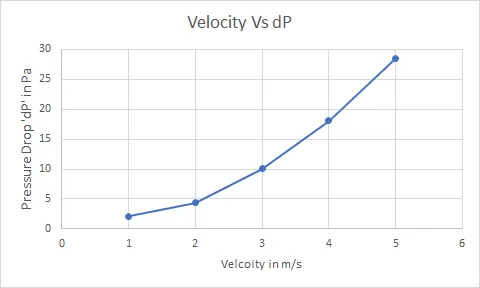
| Velocity (m/s) | Min Pressure (Pa) | Max Pressure (Pa) | dP |
| 1 | -1.236 | 0.8762 | 2.1122 |
| 2 | -0.564 | 3.7846 | 4.3486 |
| 3 | -1.31 | 8.729 | 10.039 |
| 4 | -2.36 | 15.72 | 18.08 |
| 5 | -3.73 | 24.78 | 28.51 |
Inference: The following inferences were drawn:
- Simulated for the range of velocity of flow from 1m/s to 5m/s and keep particle diameter size as 5 μm for all cases & flow velocity same as particle velocity
- Fine mesh, has resulted in no incomplete particles in all the cases and more accurate and high efficiency of the cyclone seperator
- From the case table, increasing the velocity resulted in decrease in escaped particles and increase in trapped particles. At 1m/s the number of incomplete particles was high,but by increasing the velocity there were no incomplete particles in the subsequent cases.
- Increasing the velocity --> the separation efficiency also increased. The separation efficiency is given by (number of trapped particles) / (number of tracked particles).
- Increasing the velocity --> the dp (Pressure Drop) also increased.
CONCLUSION:
The study of separation efficiency and pressure drop on the cyclone seperator was simulated successfully and the following conclusions were made:
- Particle size and separation efficiency are directly proportional
- Velocity and separtion efficiency are directly proportional and by Increasing the velocity --> the dp (Pressure Drop) also increased
- finer the mesh gives more accurate and higher the efficiency