Week 8 - Simulating Cyclone separator with Discrete Phase Modelling
Aim:- To perform analysis on cyclone separator and calculate the separation efficiency and pressure drop.
Objective:-
- To write a few words about any four empirical models used to calculate the cyclone separator efficiency.
- To perform an analysis on a given cyclone separator model by varying the particle diameter from 1 μm to 5 μm and calculate the separation efficiency in each case. Discuss the results. [Use both the velocity's as 3m/sec.]
- To perform an analysis on a given cyclone separator model by varying the particle velocity from 1 m/sec to 5 m/sec and calculate the separation efficiency and pressure drop in each case. Discuss the results. [Use particle diameter size as 5 μm for all cases & keep flow velocity same as particle velocity]
Boundary Conditions:-
Inlet and wall:- Reflect
Outlet(Top):- Escape
Outlet(Bottom/dustbin) - Trap
Note:
Structural mesh gives the best results, so you can use cutcell meshing approach available in Ansys Meshing.
Your Answers
AIM :
To perform analysis on cyclone separator and calculate the separation efficiency and pressure drop.
Objective :
- To write a few words about any four empirical models used to calculate the cyclone separator efficiency.
- To perform an analysis on a given cyclone separator model by varying the particle diameter from 1μm to 5μm and calculate the separation efficiency in each case. Discuss the results. [Use both the velocity's as 3m/sec.]
- To perform an analysis on a given cyclone separator model by varying the particle velocity from 1 m/sec to 5 m/sec and calculate the separation efficiency and pressure drop in each case. Discuss the results. [Use particle diameter size as 5μm for all cases & keep flow velocity same as particle velocity]
Introduction and theory :
Cyclonic separation is a method of removing particulates from an air, gas or liquid stream, without the use of filters, through vortex separation. When removing particulate matter from liquid, a hydro cyclone is used; while from gas, a gas cyclone is used. rotational effects and gravity are used to separate mixtures of solids and fluids. The method can also be used to separate fine droplets of liquid from a gaseous stream.
A high-speed rotating (air)flow is established within a cylindrical or conical container called a cyclone. Air flows in a helical pattern, beginning at the top (wide end) of the cyclone and ending at the bottom (narrow) end before exiting the cyclone in a straight stream through the centre of the cyclone and out the top. Larger (denser) particles in the rotating stream have too much inertia to follow the tight curve of the stream, and thus strike the outside wall, then fall to the bottom of the cyclone where they can be removed. In a conical system, as the rotating flow moves towards the narrow end of the cyclone, the rotational radius of the stream is reduced, thus separating smaller and smaller particles. The cyclone geometry, together with volumetric flow rate, defines the cut point of the cyclone. This is the size of particle that will be removed from the stream with a 50% efficiency. Particles larger than the cut point will be removed with a greater efficiency, and smaller particles with a lower efficiency as they separate with more difficulty or can be subject to re-entrainment when the air vortex reverses direction to move in direction of the outlet.
An alternative cyclone design uses a secondary air flow within the cyclone to keep the collected particles from striking the walls, to protect them from abrasion. The primary air flow containing the particulates enters from the bottom of the cyclone and is forced into spiral rotation by stationary spinner vanes. The secondary air flow enters from the top of the cyclone and moves downward toward the bottom, intercepting the particulate from the primary air. The secondary air flow also allows the collector to optionally be mounted horizontally, because it pushes the particulate toward the collection area, and does not rely solely on gravity to perform this function.
Large scale cyclones are used in sawmills to remove sawdust from extracted air. Cyclones are also used in oil refineries to separate oils and gases, and in the cement industry as components of kiln preheaters. Cyclones are increasingly used in the household, as the core technology in bagless types of portable vacuum cleaner and central vacuum cleaners. Cyclones are also used in industrial and professional kitchen ventilations for separating the grease from the exhaust air in extraction hoods. Smaller cyclones are used to separate airborne particles for analysis. Some are small enough to be worn clipped to clothing, and are used to separate respirable particles for later analysis.
Empirical models used to calculate cyclone separator efficiency:
- Iozia and Leith Model
This model is developed on the concept of force balance wherein it assumes that the particles conveyed by the vortex is acted upon by two forces; centrifugal and flow resistance forces. It's prediction of collection efficiency,
- Li and Wang Model
This model implements the particle bounce or re-entrainment and turbulent diffusion effects at the walls of the separator based on the following assumptions:
- Radial particle velocity and radial concentration are not constant for uncollected particles within the device.
- Tangential velocity with respect to the radius of the cyclone is related as
u.R^n = constant
- Koch and Licht Model
This model acknowledges the pre-dominantly turbulent nature of flow within the cyclone separator and distribution of fluid residence times. Also, particle motion in entry and collection regions were described with the following supplementary assumptions:
- Tangential velocity of particle and gas flow are equal to each other i.e., no slip between the particles and gas flow in the tangential direction.
- Similar to the Li and Wang model, tangential velocity with respect to the radius of the cyclone is related as u.R^n = constant
- Lapple Model
This model like the Iozia and Leith Model and the Koch and Licht Model is based on force balance, however, without considering flow resistance. The model assumes that particles entering the cyclone are evenly distributed across the inlet. Particles travelling from the inlet half width to the walls of the separator is collected with 50% efficiency and the semi-empirical relationship to calculate 50% cut diameter
Modelling approach:
Pre-processing:
In pre-processing we first import the geometry in space-claim and do the volume extract by selecting the edges, and then supress the other geometry body .
Going next, we close the space claim and open the meshing module, and create the mesh to model. Here we use the cartesian method of meshing
Cartesian Mesh:
A Cartesian mesh generator requires a surface mesh as the basis for the generation process. The surface mesh has to satisfy certain constraints:
- If gaps between surfaces are permitted then those gaps have to be significantly smaller than the local Cartesian mesh elements to prevent the Cartesian elements leaking inside the geometry.
- To accurately capture curvature the surface facets, have to be significantly smaller than the local Cartesian mesh elements, otherwise no matter how much you refine the Cartesian mesh you will end up with better resolution of the wrong geometry (i.e., facets) and not the original smooth representation.
- Once a faceted representation is passed to a Cartesian mesh generator there is usually no recourse back to the original geometry during the cell generation process which introduces inaccuracies if the original geometry was analytic (e.g., NURBS), and this inaccuracy is amplified in high curvature regions.
- Often the transfer format (e.g., STL) for a Cartesian mesh generator does not carry with it the topology of the original geometry, meaning you have to use error prone angle-based facet splitting to recover the feature edges of the boundaries.
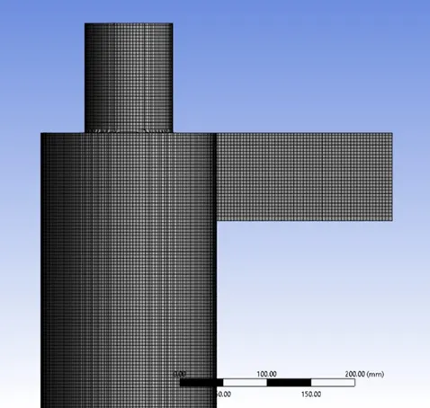
Fig 1. Cartesian Mesh
Setup:
Solver :
In solver we used the pressure based solver with steady time solver with applying the gravity at y axis.
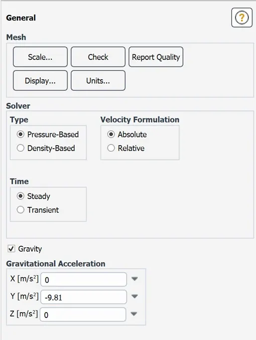
Fig 2. Solver setup
Viscous model:
We select the k-epsilon RNG model with swirl dominated flow on and standard wall function. K-epsilon RNG model is slight updated k-epsilon model which enhance the accuracy of swirling flow.
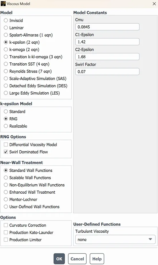
Fig 3. Viscous model
Discrete phase modelling:
A division of multiphase flows is the discrete phase model. When attempting to analyse the behaviour of the particles from both a Lagrangian and discrete perspective, a discrete phase model (DPM) is often employed via Ansys Software. The difference between the Lagrangian and Eulerian views is that the Eulerian perspective assumes a finite volume element in the fluid flow route while the Lagrangian view bases its analysis of fluid behaviour on particle tracking of a particulate flow.
Navier-Stokes equations are used in the discrete phase model to solve the continuous phase. Countless particles, bubbles, or droplets are tracked at once to approximate the discrete phase. Specifically, those that cross the predicted continuous flow field.
In discrete phase modelling there are two ways of carrying discrete phase modelling one is coupled flow and uncoupled flow in uncoupled flow the discrete phase and continuous phase have no contact with each other. While in coupled flow the discrete phase will influence the continuous phase. But the size of particle injected into the cyclone separator are very small usage of both the flow doesn’t matter much but we use the coupled flow so we enabled the interaction with continuous phase
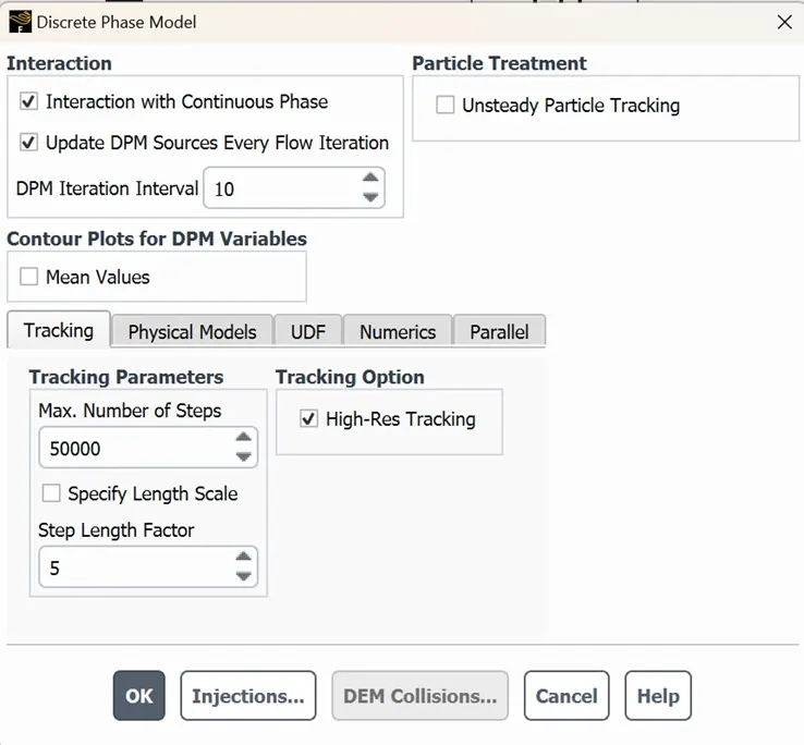
Fig 4. Discreate phase modelling setup
We creates the injection in DPM by clicking on injection and then crate one in which we have to describe the properties that what are the things going to flow through it and at what velocity they are going to flow (here our velocity of particle is in m/s and size of particle is µm)
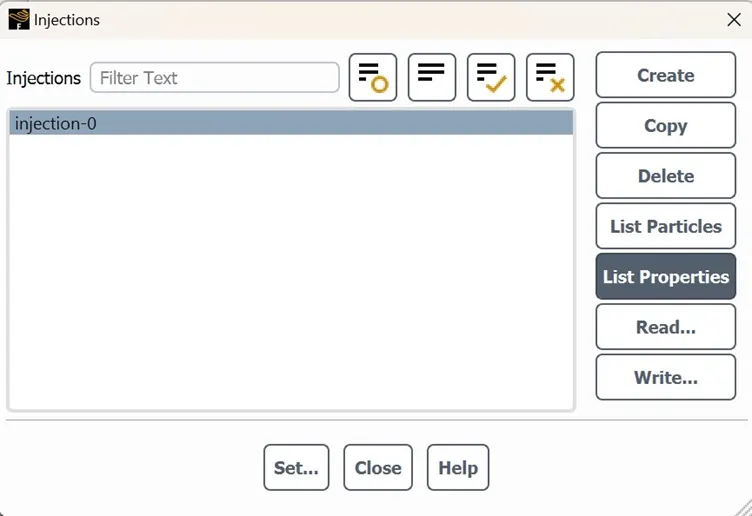
Fig 5. Injection setting
We have two case here in one we have to change the particle size and in other we have to change the velocity so we will do these things in DPM injections.
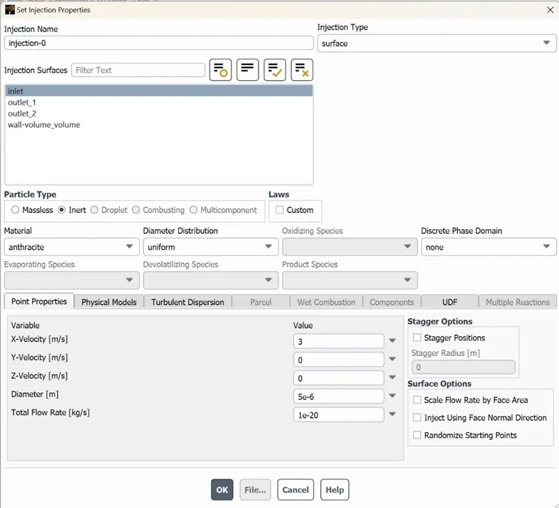
Fig 6. Flow velocity and particle size
Here in boundary condition we set the DPM where the particle should be trap where it should be escape and where it should be reflect according to cyclone seperator:
Inlet: reflect
Top-outlet: escape
Bottom outlet: trap
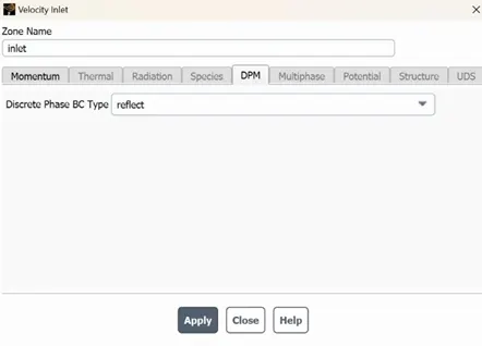
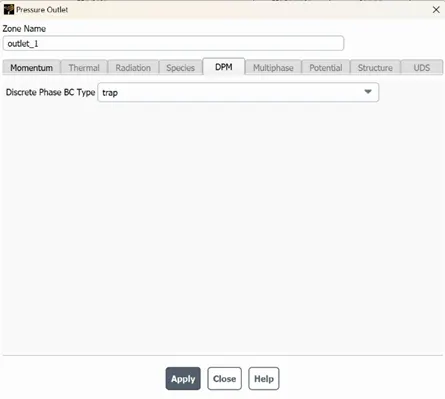
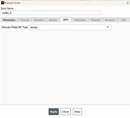
Fig 7. Setting DPM in boundaries condition
Solution method:
In solution method we select SIMPLE scheme and second order turbulent kinetic energy and second order upwind to turbulent dissipation rate because second order upwind is more accurate in special discretise scheme.
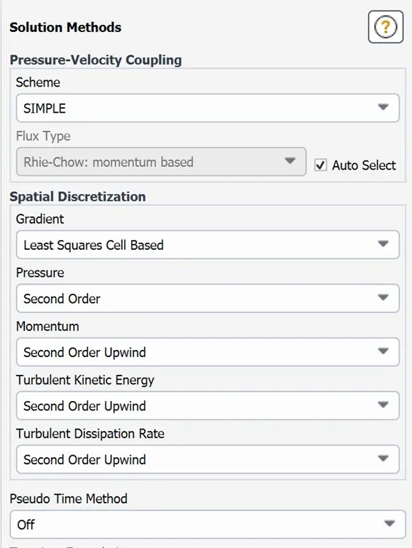
Fig 8. Solution method
Then we do the standard initialization with defining the inlet point as point of starting simulation. And run the calculation after the calculation we first export the particle history data which we requires in simulation during post processing
Post-processing:
In post processing we first import the particle history data file which creates the anthracite flow along the cylinder like how much time particle traveling in cyclone separator and also using this file we can track the particles flow.
Case 1. To perform an analysis on a given cyclone separator model by varying the particle diameter from 1 μm to 5 μm and calculate the separation efficiency in each case. Discuss the results. [Use both the velocity's as 3m/sec.]
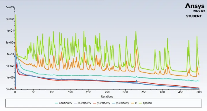
Fig 9. Scaled residuals for 3m/s velocity and 1μm particle size
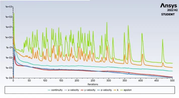
Fig 10. Scaled residuals for 3m/s velocity and 3μm particle size
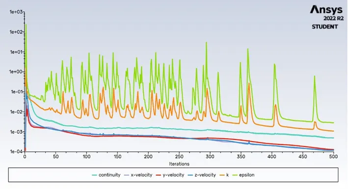
Fig 11. Scaled residuals for 3m/s velocity and 5μm particle size
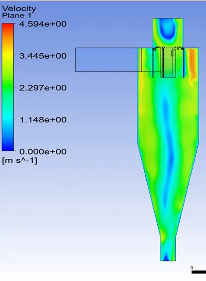
Fig 12. Velocity contour at 3m/s
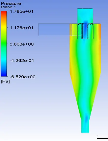
Fig 13. Pressure contour at velocity 3m/s
Efficiency calculation:
We calculates the efficiency by dividing the number of particles tracked by total number of particles flow.

Fig 14. Number of particles tracked at 3m/s velocity and 1μm particle size
From fig 14 we can see 324 out off 378 particles tracked when 1μm is particle size
So, separator efficiency = (particle trapped /total particle tracked) *100
= (324/378)*100 = 85.71% efficiency

Fig 15. Number of particles tracked at 3m/s velocity and 3μm particle size
So, separator efficiency = (particle trapped /total particle tracked) *100
= (330/378)*100 = 87.30% efficiency

Fig 16. Number of particles tracked at 3m/s velocity and 5μm particle size
So, separator efficiency = (particle trapped /total particle tracked) *100
= (310/378)*100 = 82.01% efficiency
Simulation video link:
Link for velocity 3m/s and particle 1µm
https://drive.google.com/file/d/1_f_F_M0uxHNPc2_ztgyDLSAYdAIXz7MJ/view?usp=share_link
Link for velocity 3m/s and particle 1µm
https://drive.google.com/file/d/1Pg-FyVnklTTliIMBoyc2OOUwVhdoJ__C/view?usp=share_link
Link for velocity 3m/s and particle 1µm
https://drive.google.com/file/d/1pOrgnmGXXxh77vz1RhENlWwgyh8Gq0wO/view?usp=share_link
Case 2. To perform an analysis on a given cyclone separator model by varying the particle velocity from 1 m/sec to 5 m/sec and calculate the separation efficiency and pressure drop in each case. Discuss the results. [Use particle diameter size as 5 μm for all cases & keep flow velocity same as particle velocity]
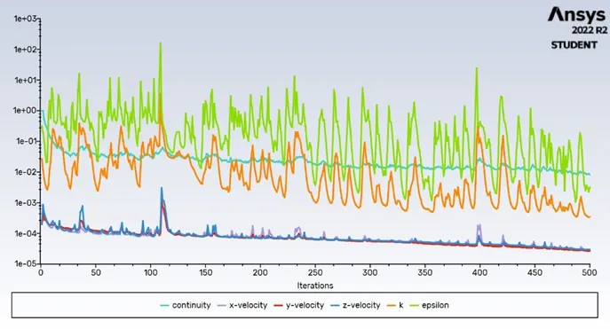
Fig 17. Scaled residuals for 1m/s velocity and 5μm particle size
Fig 18. Scaled residuals for 3m/s velocity and 5μm particle size
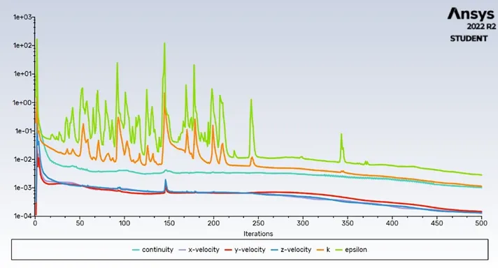
Fig 19. Scaled residuals for 5m/s velocity and 5μm particle size
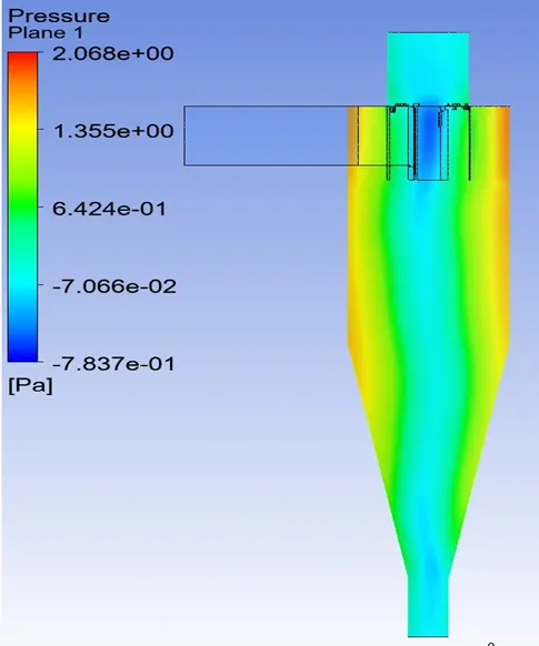
Fig 20. Pressure contour for velocity 1m/s and particle size 5µm
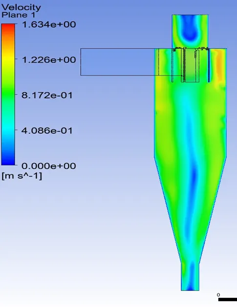
Fig 21. Velocity contour for velocity 5m/s and particle size 5µm
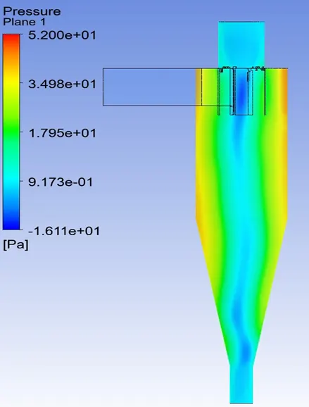
Fig 22. Pressure contour for velocity 5m/s and particle size 5µm
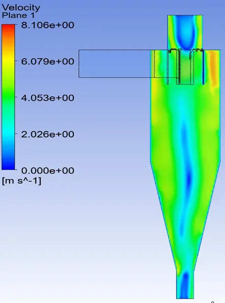
Fig 23. Velocity contour for velocity 5m/s and particle size 5µm
Efficiency calculation:
We calculates the efficiency by dividing the number of particles tracked by total number of particles flow.

Fig 24. Number of particles tracked at 1m/s velocity and 5μm particle size
From fig 24 we can see 324 out off 378 particles tracked when 1μm is particle size
So, separator efficiency = (particle trapped /total particle tracked) *100
= (314/378)*100 = 83.06% efficiency

Fig 25. Number of particles tracked at 1m/s velocity and 5μm particle size
So, separator efficiency = (particle trapped /total particle tracked) *100
= (188/378)*100 = 49.73% efficiency
Simulation link:
Link for velocity 1m/s and particle 5µm
https://drive.google.com/file/d/1fJsmBl3KUQ6kyyv1JmXSWjxJxpKd0O7t/view?usp=share_link
Link for velocity 5m/s and particle 5µm
https://drive.google.com/file/d/1SoMOMkfv5UYsNwAOtIU8cGDvmYnwvdba/view?usp=share_link
Conclusion:
- In conclusion we conclude that if the velocity increases the efficiency going to fall for 5µm particle size.
- And if we kept velocity 3m/s and particle size increases at certain level then the efficiency will be affect