Simulation of Cyclone separator with Discrete Phase Modelling
Objective:-
To perform analysis on cyclone separator including the following
- To write a few words about any four empirical models used to calculate the cyclone separator efficiency.
- To perform an analysis on a given cyclone separator model by varying the particle diameter from 1 μm to 5 μm and calculate the separation efficiency in each case. Discuss the results. [Use both the velocities as 3m/sec.]
- To perform an analysis on a given cyclone separator model by varying the particle velocity from 1 m/sec to 5 m/sec and calculating the separation efficiency and pressure drop in each case. Discuss the results. [Use particle diameter size as 5 μm for all cases & keep flow velocity same as particle velocity]
Structural mesh gives the best results, so you can use the cut cell meshing approach available in Ansys Meshing.
Boundary Conditions:-
Inlet and wall:- Reflect
Outlet(Top):- Escape
Outlet(Bottom/dustbin) - Trap
Solution:
What exactly is a cyclone separator and how does it work?
Ordinarily, a cyclone separator is manufactured by welding of the common steel plate and is applicable for occasions requiring less air purity relatively. If there needs a high standard of air purity, the adopting of electrolytic or stainless steel plate in the process can meet the requirement.
Working Principle
Cyclone separator utilizes cyclone centrifugal force to separate granules from the air. As the below picture, granules containing air firstly enter the inner cyclone separating area of the hopper through the inlet. In this area, the direction of the air is changed from direct entering to down-run with a spiral rotating along the screw (as a solid line). The high-density dust particles are dragged to the hopper lining by centrifugal force. With the air rotating along the screw and the entering of cone part, spiral airflow inside the hopper flows to the center as hopper diameter is reduced. In lessened centrifugal force, granules are exhausted along with the inside hopper to the outlet. However, the secondary vortex flow will be formed when airflow reaches the ending part of the cone hopper and will be expelled via the upper exhausting pipe of the cone part.
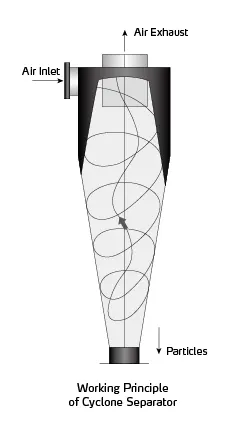
There are various proportions and styles of the cyclone separator, which generate different pressure losses. Usually, the pressure loss of the cyclone separator is about 50~200mm Aq.
When cyclone separator is used in positive pressure conveying system, with the large conveying pressure, even there’s much pressure loss of the cyclone separator, it just makes a little influence on the conveying effect. We generally attach more attention to the separation effect.
In negative pressure conveying system, the air-source equipment usually has low suction pressure, the less pressure loss of cyclone separator, the better. In designing the cyclone separator, it should estimate its pressure loss precisely, and calculate the output pressure of the air-source equipment.
Separation Effect
Ordinarily, the cyclone separator is applicable to separate the non-viscous, nonfiber dry dust greater than 1-3 micrometers. By accurate calculation and appropriate technological structure, it can get supreme separation effect eventually. For large size granules, the separating rate can reach above 97%. The granule in a smaller size or is more light, the more difficult to separate effectively.
Application
Currently, the cyclone separators are widely used in Shini products, they always appear on occasions that need air-solid separation. The products include HCF Cyclone Dust Separator, ACF Cyclone Dust Collector, Blower Conveying & Cyclone Dust Collector of Shini Granulator, and the conveying device of Shini Sound-proof Central Granulator.
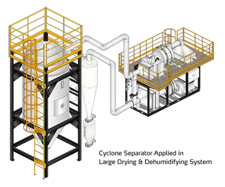
For some plastic materials, like PET or others, during the process of pre-crystallizing, drying and dehumidifying, and conveying, which contain the granules or many granules generated by friction. If there’s no pre-separation for granules in the drying air of the return loop or in the conveying recycling process, it will block the return-air filter or the front-seat filter soon, and affect the ventilation which eventually influences the material drying and conveying capacity. Especially for large drying and dehumidifying or conveying system, granules containing airflow will affect the filter seriously. Therefore, before drying air return or conveying air passing through the filter, making it get through the cyclone separator at first can lessen the filter’s cleanliness and improve the operating efficiency.
1. To write a few words about any four empirical models used to calculate the cyclone separator efficiency.
CYCLONE EFFICIENCY EMPIRICAL MODELS are 4 kinds.
IOZIA AND LEITH MODEL
Lozia and Leith's (1990) logistic model is a modified version of Barth's (1956) model which is developed based on force balance. The model assumes that a particle carried by the vortex endures the influence of two forces: a centrifugal force, Z, and flow resistance, W. Core length, Zc, and core diameter, dc, are given as
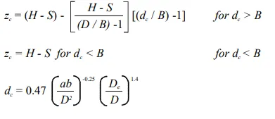
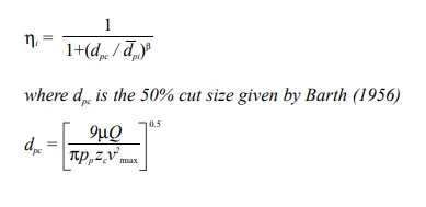
The addition made by Iozia and Leith on the original Barth (1956) model is the core length Zc and slope parameter β expression which is derived based on the statistical analysis of experimental data of cyclone with D = 0.25 m. The collection efficiency ηi of particle diameter dpi can be calculated from
LI AND WANG MODEL
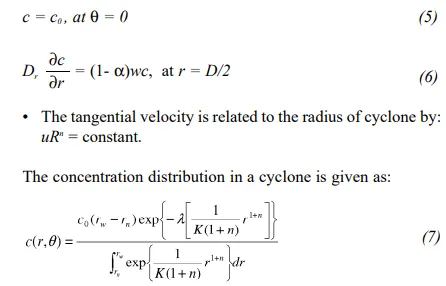
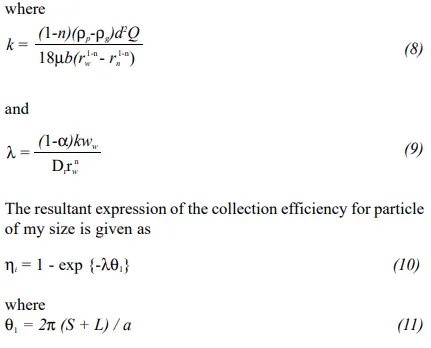
The Li and Wang (1989) model include particle bounce or re-entrainment and turbulent diffusion at the cyclone wall. A two-dimensional analytical expression of particle distribution in the cyclone is obtained. Li and Wang's model was developed based on the following assumptions:
- The radial particle velocity and the radial concentration
the profile is not constant, for uncollected particles within the
cyclones. - Boundary conditions with the consideration of turbulent
the diffusion coefficient and particle bounce re-entrainment on
the cyclone wall is:
KOCH AND LICHT MODEL
Koch and Licht's (1977) collection theory recognized the inherently turbulent nature of cyclones and the distribution of gas residence times within the cyclone. Koch and Licht describe particle motion in the entry and collection regions with the additional following assumptions:
- The tangential velocity of a particle is equal to the tangential velocity of the gas flow, i.e. there is no slip in the tangential direction between the particle and the gas.
- The tangential velocity is related to the radius of the cyclone by uRn = constant.
A force balance and an equation on the particles collection yields the grade efficiency ηi.
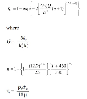
G is a factor related to the configuration of the cyclone, n is related to the vortex and τ is the relaxation term.
LAPPLE MODEL
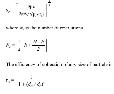
Lapple's (1951) model was developed based on force balance without considering the flow resistance. Lapple assumed that a particle entering the cyclone is evenly distributed across the inlet opening. The particle that travels from the inlet half-width to the wall in the cyclone is collected with 50% efficiency. The semi-empirical relationship developed by Lapple (1951) to calculate a 50% cut diameter, dpc, is
2. To perform an analysis on a given cyclone separator model by varying the particle diameter from 1 μm to 5 μm and calculate the separation efficiency in each case. Discuss the results. [Use both the velocities as 3m/sec.]
We are going to run a few simulations on cyclone separators with varying particle diameters and draw conclusions on separation efficiency in each case. the velocities will 3ms-1.
first, we are going to add and export the model in SpaceClaim and then proceed to fluent for simulation and post-process the result. We extract the fluid volume from it and go for meshing.
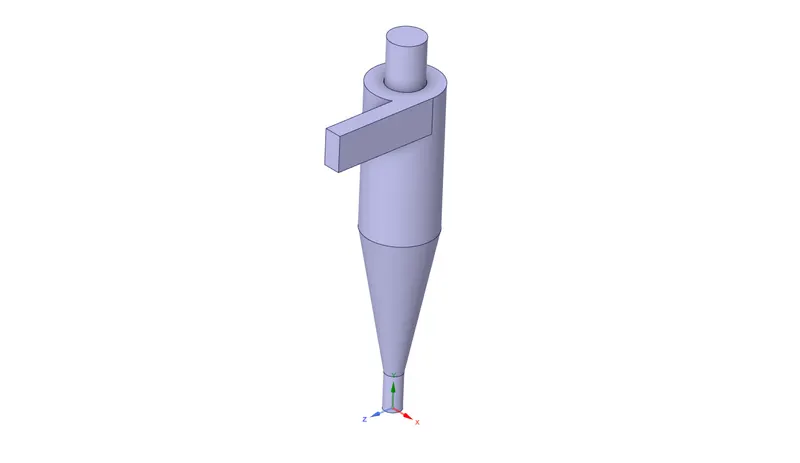
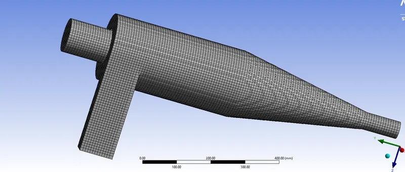
here normal element size meshing is quite good and we have to give cartesian cut cell structural meshing for more accurate results.
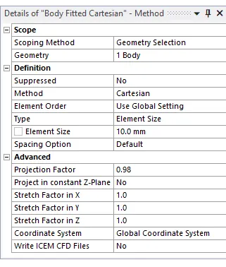
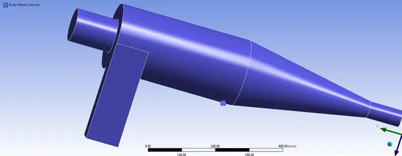
now we move on to fluent for setting up the simulation part.
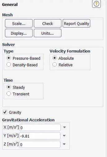
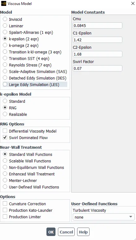
We added gravity factor along Y and we consider the RNG type K-epsilon turbulence modeling here. One extra added feature is the Swirl Dominated flow which determines what type of viscous flow pattern is present inside our setup.
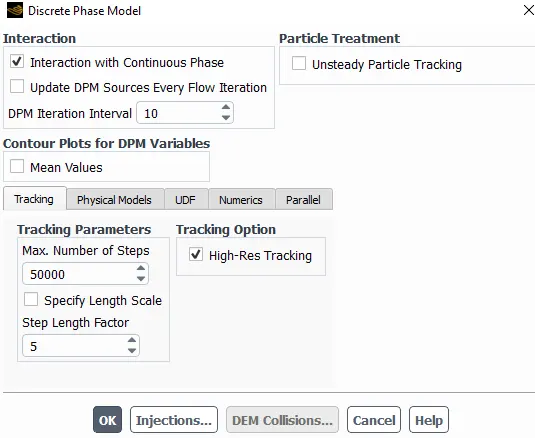
and then we add Discrete Pashe model or continuous flow of very fine particles from inlet to outlet.
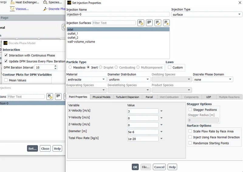
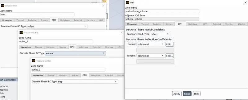
As for Boundary conditions we have,
Boundary Conditions:-
Inlet and wall:- Reflect
Outlet(Top):- Escape
Outlet(Bottom/dustbin) - Trap
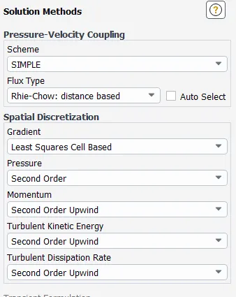
then we select METHODS of how to solve the transport equations.
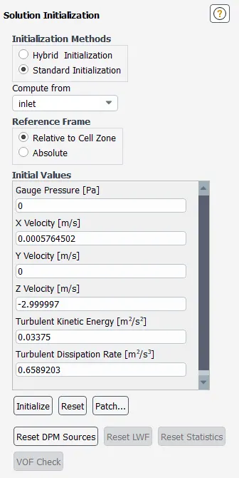
and then we INITIALIZE with setting and computing from INLET.
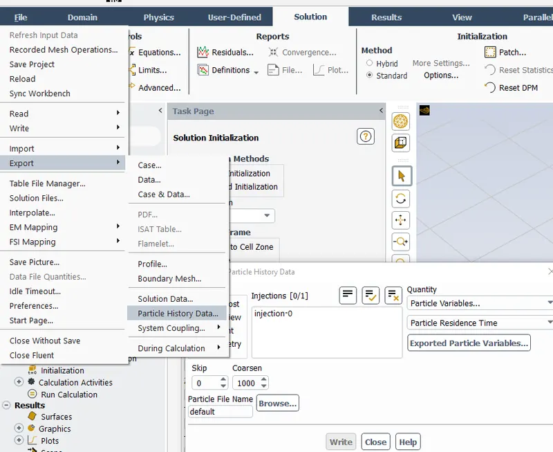
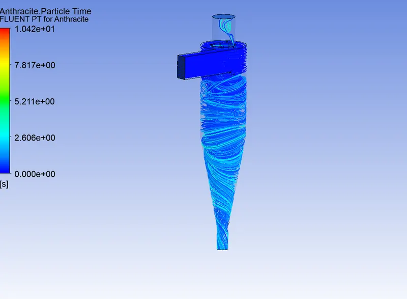
and Once the simulation is complete we export PARTICLE HISTORY DATA so that we can post-process the particles in CFD and visualize the vortex results.
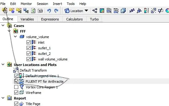
this is how e import data to CFD-POST:
In CFD-POST this is how we import here:
OUTPUT:
We have to display the output by varying the particle diameter from 1 μm to 5 μm, so we have 5 cases. And determine the Separation efficiency and pressure drop.
2. To perform an analysis on a given cyclone separator model by varying the particle diameter from 1 μm to 5 μm and calculate the separation efficiency in each case. Discuss the results. [Use both the velocities as 3m/sec.]
1. particle Diamter: 1 μm & Particle Velocity: 3ms-1
Separation efficiency: (Number tracked / escaped + trapped) * 100
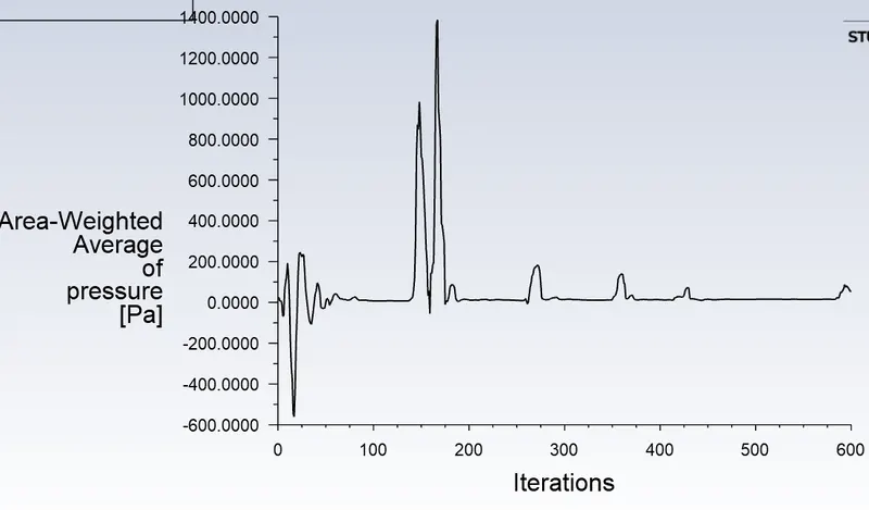
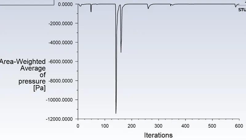
Pressrue drop = Outlet - Inlet
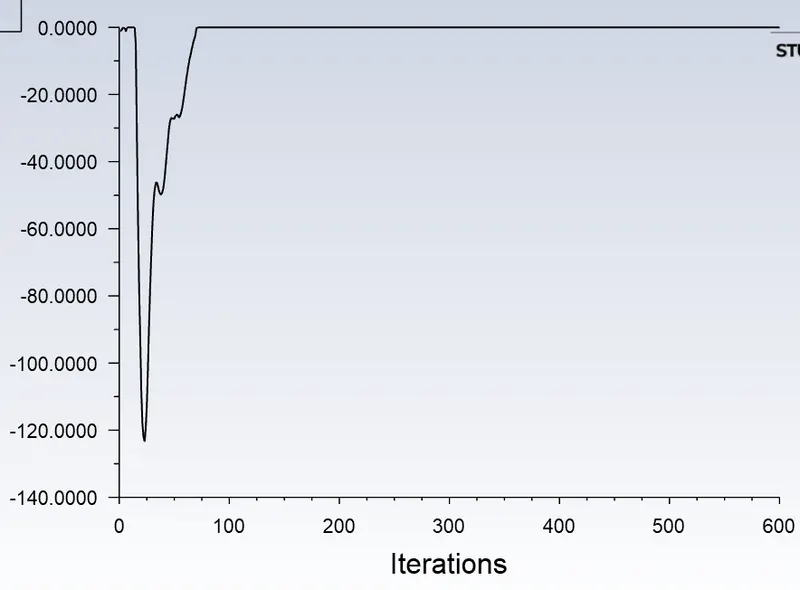
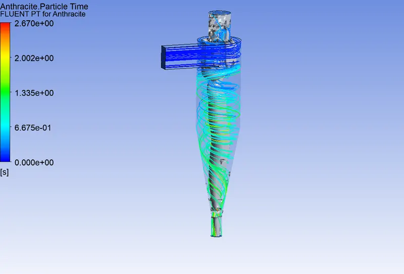
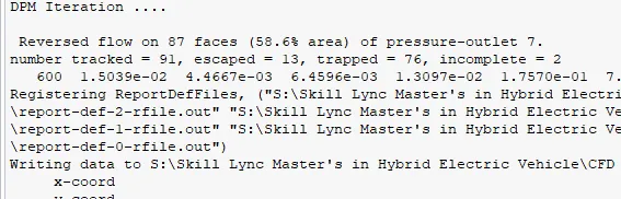
Separation efficiency: 13 + 76 / 91
=89/91 = 0.97*100 = 97%
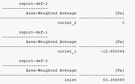
Pressrue Drop = 53-12 = 61Pa
2. particle Diamter: 2 μm & Particle Velocity: 3ms-1
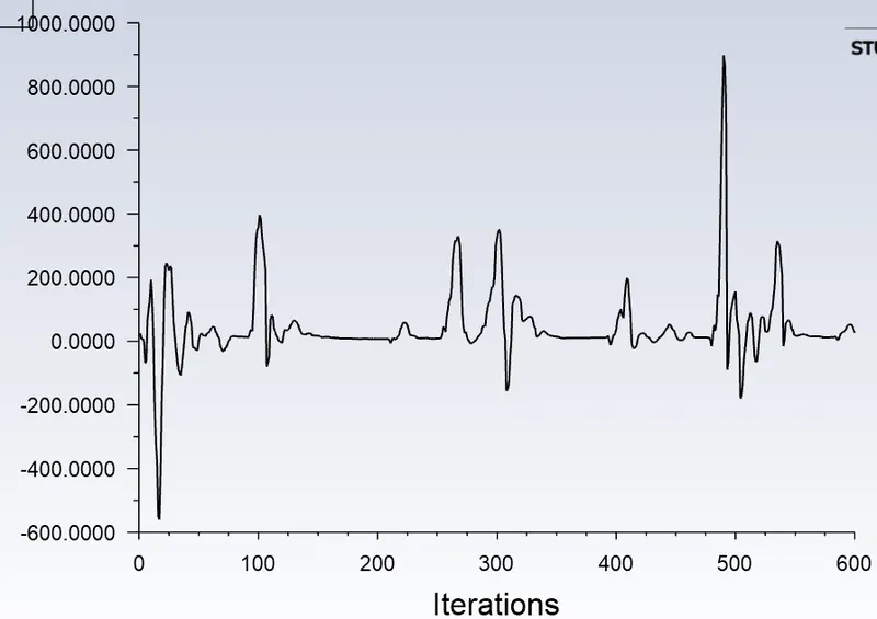
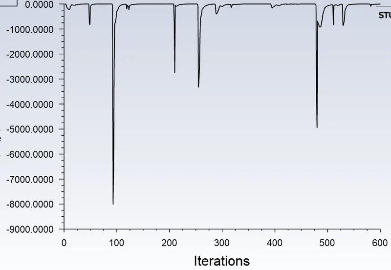
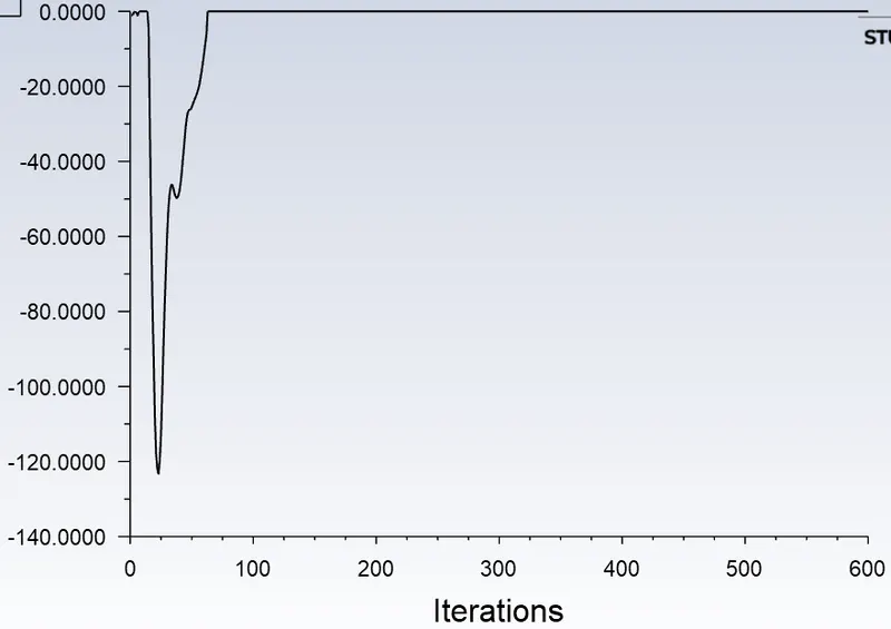
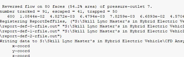
separation efficiency = 100%
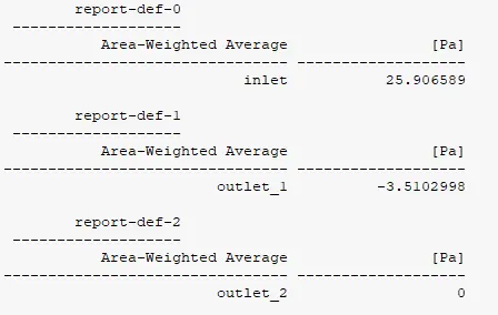
pressure drop = 22Pa
3. particle Diamter: 3 μm & Particle Velocity: 3ms-1
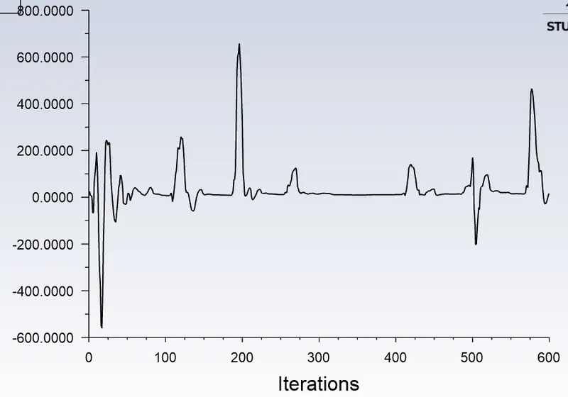
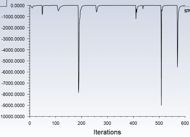
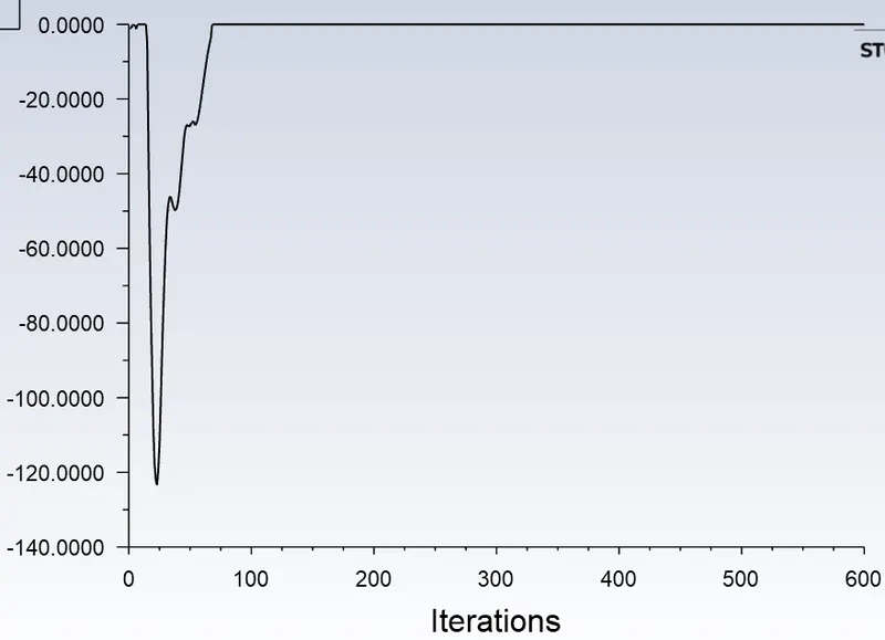
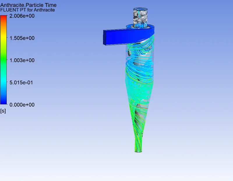
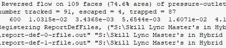
Separation efficiency: 100%
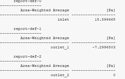
pressure drop = 8Pa
4. particle Diamter: 4 μm & Particle Velocity: 3ms-1
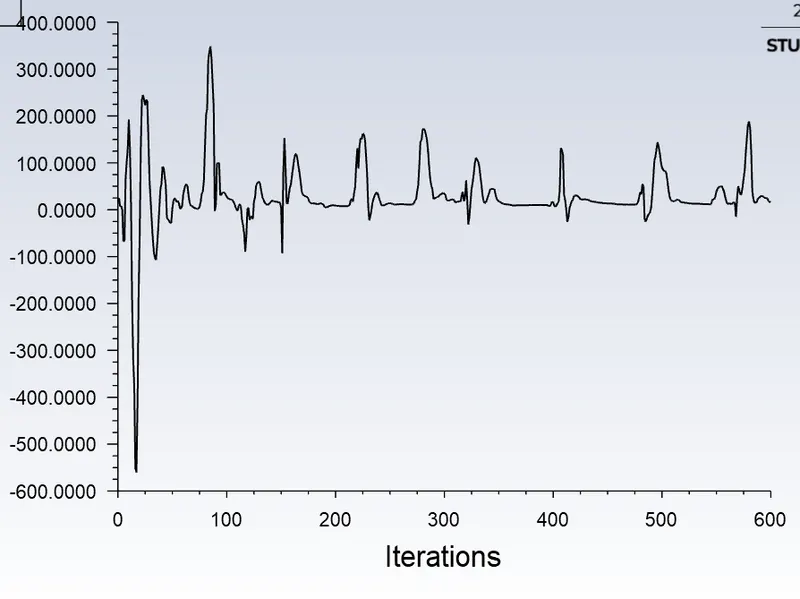
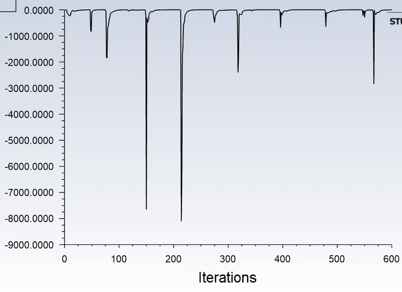
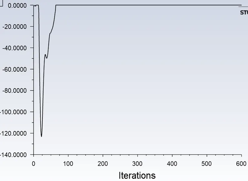
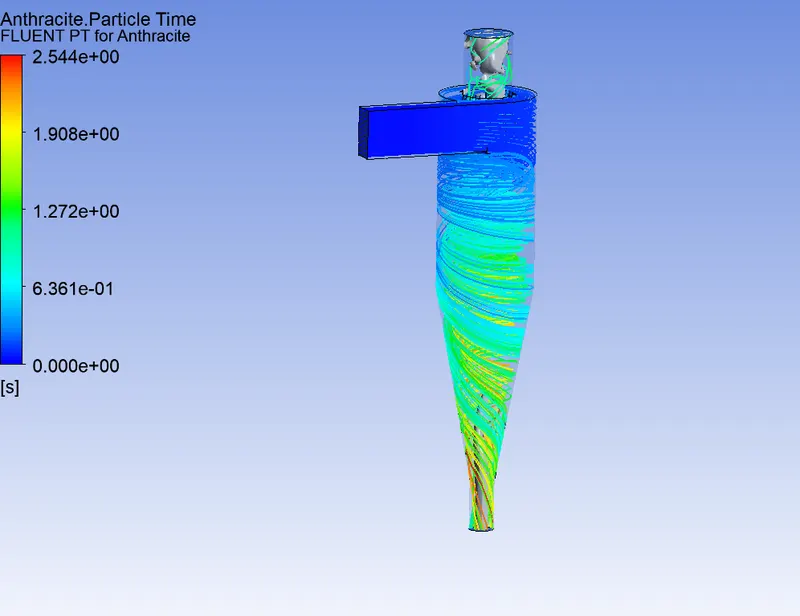
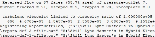
Separation efficiency: 91%
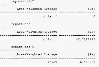
Pressrue drop : 14Pa
5. particle Diamter: 5 μm & Particle Velocity: 3ms-1
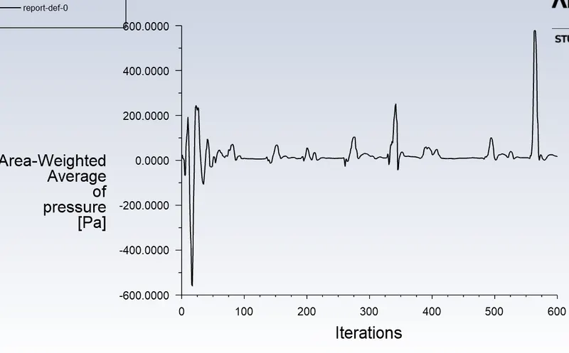
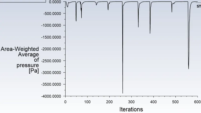
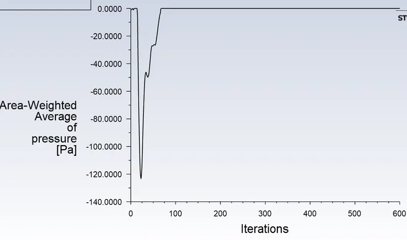
separation efficiency: 97%
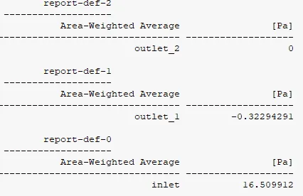
16Pa is the pressure drop.
3. To perform an analysis on a given cyclone separator model by varying the particle velocity from 1 m/sec to 5 m/sec and calculating the separation efficiency and pressure drop in each case. Discuss the results. [Use particle diameter size as 5 μm for all cases & keep flow velocity same as particle velocity]
1. particle Diamter: 5 μm & Particle Velocity: 1 ms-1 and Inlet Velocity = 1ms-1
Separation efficiency: (Number tracked / escaped + trapped) * 100
Pressrue drop = Outlet - Inlet
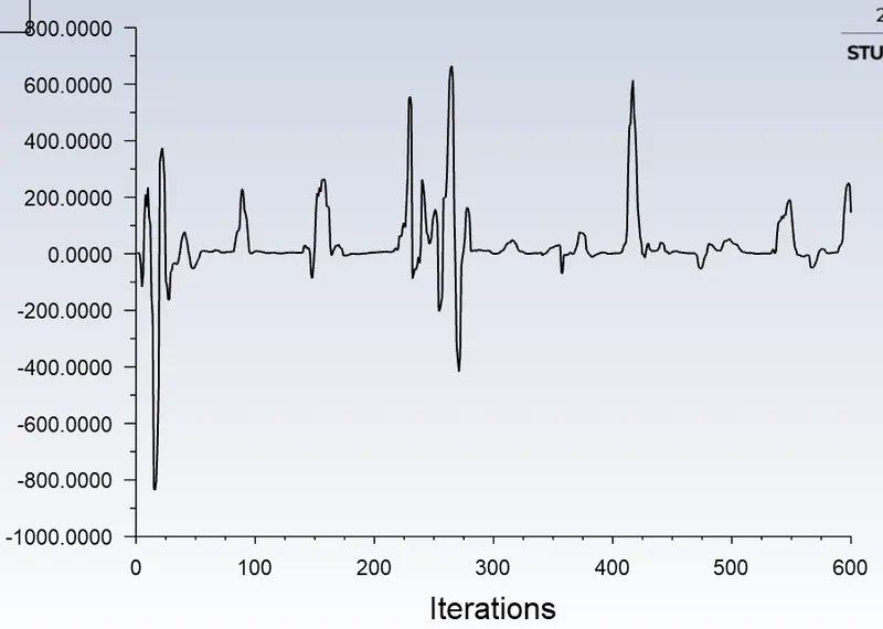
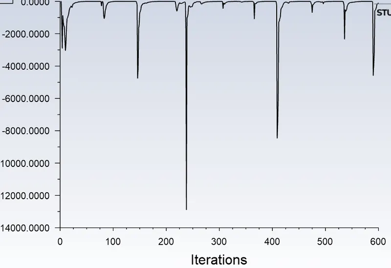
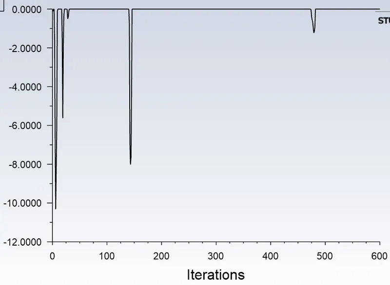
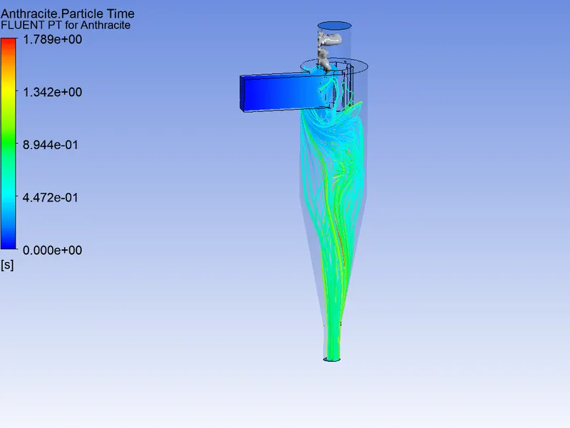
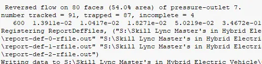
Separation efficiency: 95%
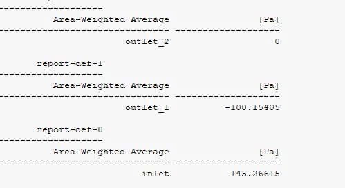
Pressure drop = 45Pa
2. particle Diamter: 5 μm & Particle Velocity: 2 ms-1 and Inlet Velocity = 2 ms-1
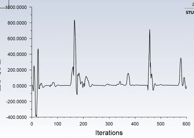
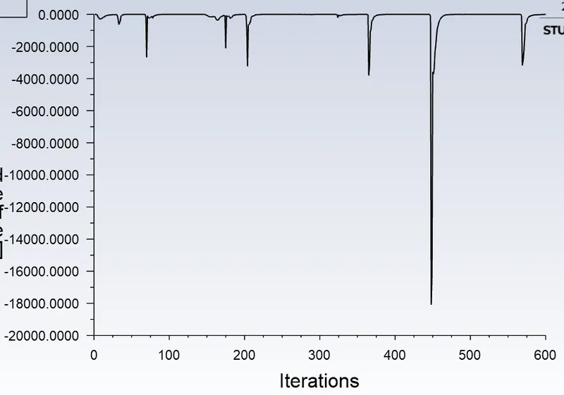
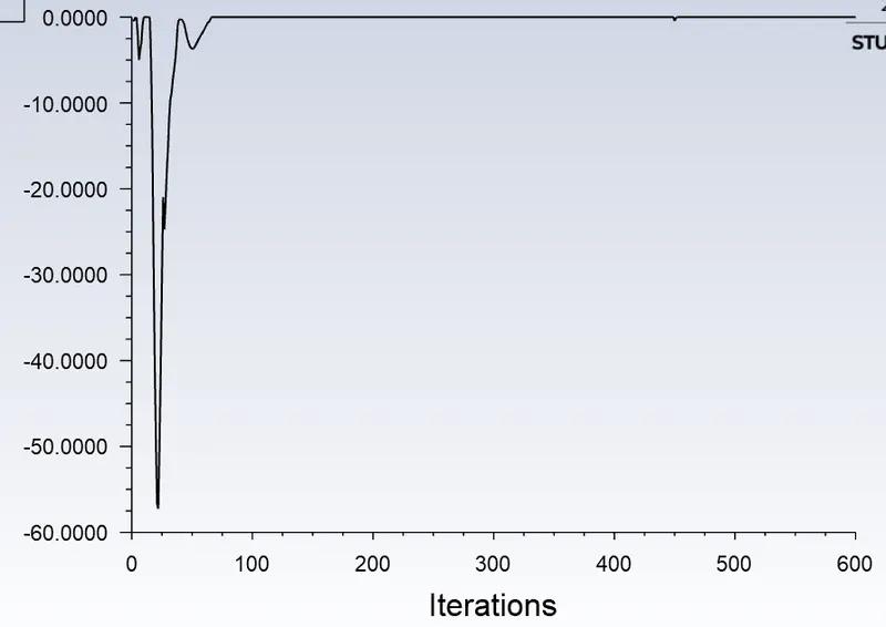
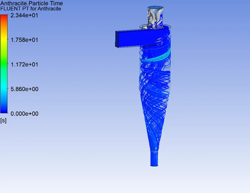
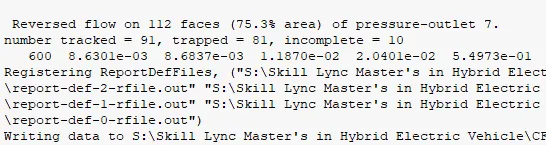
separation efficiency: 89%
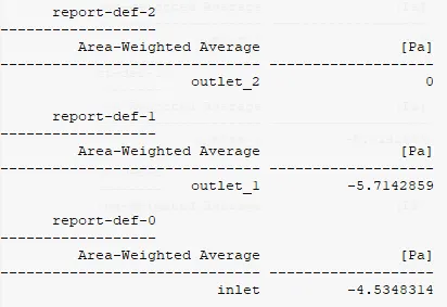
Pressure drop: 1Pa
3. particle Diamter: 5 μm & Particle Velocity: 3 ms-1 and Inlet Velocity = 3 ms-1
separation efficiency: 97%
16Pa is the pressure drop.
4. particle Diamter: 5 μm & Particle Velocity: 4 ms-1 and Inlet Velocity = 4 ms-1
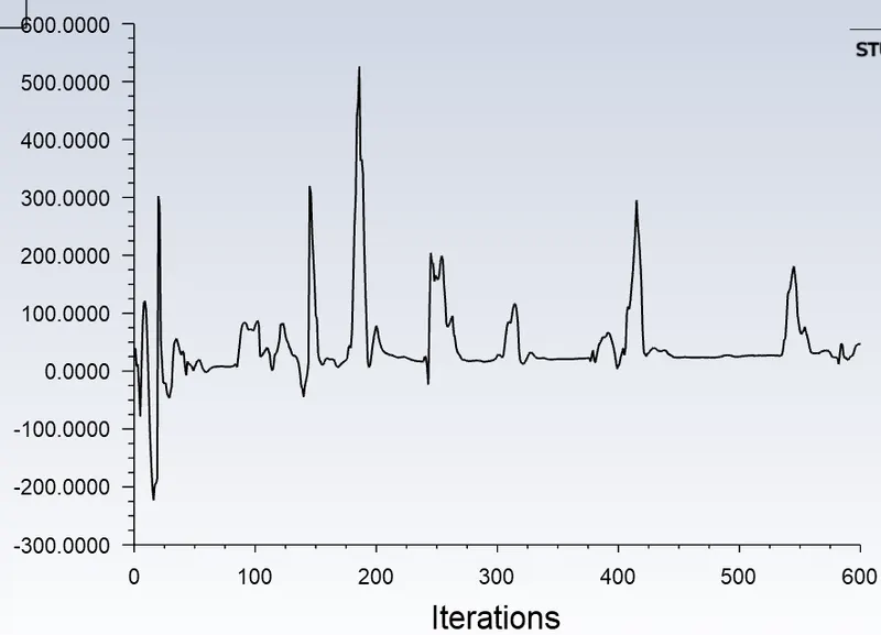
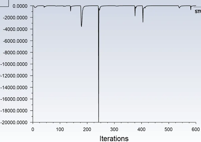
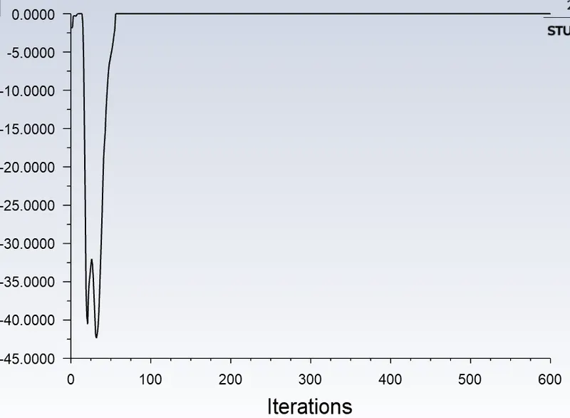
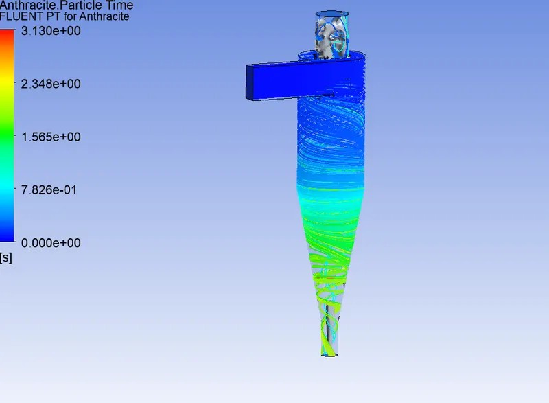
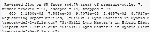
Separation efficiency: 100%
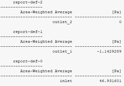
Pressure drop: 45Pa
5. particle Diamter: 5 μm & Particle Velocity: 4 ms-1 and Inlet Velocity = 4 ms-1

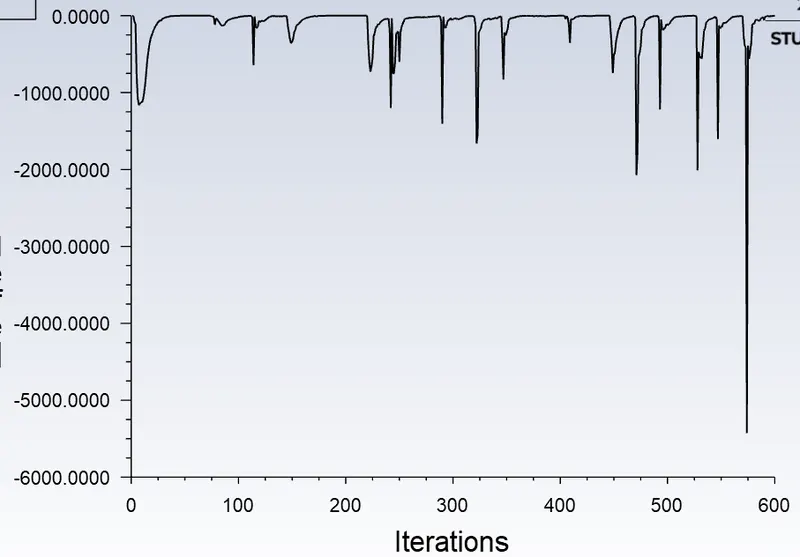
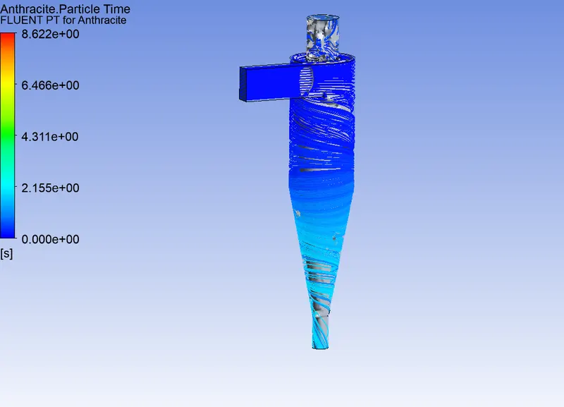
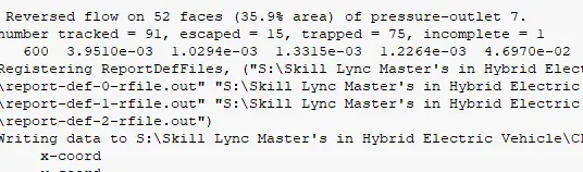
Separation efficiency: 98%
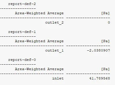
Pressure drop = 39Pa
References: