Week 8 Multi cell Battery Pack
Aim:- Multi cell Battery Pack
Object:-How weakest cell limits the usable capacity of the battery pack? What is the solution?
What is battery pack?
A battery pack is a set of any number of (preferably) identical batteries or individual battery cells They may be configured in a series, parallel or a mixture of both to deliver the desired voltage, capacity, or power density. The term battery pack is often used in reference to Radio Controlled Hobby Toys and Battery Electric Vehicle.
Components of battery packs include the individual batteries or cells, and the interconnects which provide electrical conductivity between them. Rechargeable battery packs often contain a temperature sensor, which the battery charger uses to detect the end of charging. Interconnects are also found in batteries as they are the part which connects each cell, though batteries are most often only arranged in series strings.
Battery configuration
The battery configuration in series or parallel connection can have a different voltage on each cell. The weakest cell in the battery pack could have more stress than other cells so that it will become the fastest damage. This research will find the weakest cell in the battery pack. The identification of the weakest cell is performed on the charging and discharging process with direct measurement. The result shows that the weakest cell located in the middle of the battery pack. The weakest cell have 2.75 V and the health battery cell have 2.9 V.
The weakest cell may affect the battery pack by the following condition-
1. It will carry out a limit on complete operation of the battery pack.
2. Due to weakest cell reaching the limit earlier than others, the battery pack may be under utilized.
3. During weakest cell condition it is important to protect an individual cell over voltage under voltage limits apply to all series connected cells.
4. It imposes a limit on overall operation battery pack.
Problem with a weak cell in battery pack-
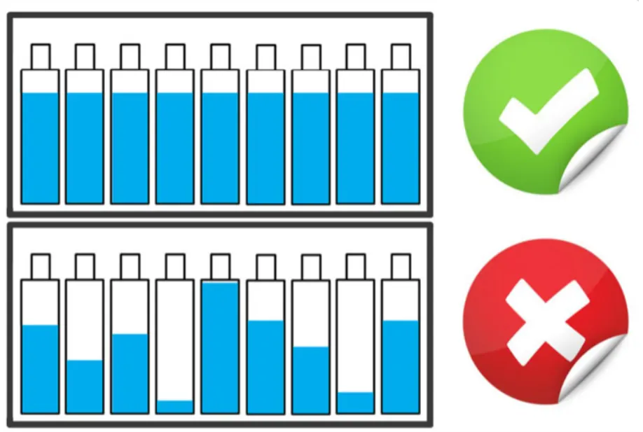
1. Mainly there are two prime mismatches which affects the overall output of the battery pack and they are-
1. State of Charge(SoC) Mismatch
2. Capacity/ Energy(C/E) Mismatch
2. Each problems limits the pack capacity(mAh) to the capacity of the weakest cell and it is important to recognize.
3. These type of cell to cell varitaion more likely occure in Li-ion prismatic cells, due to more extreme mechanical stresses.
4. However weak cells (ones with lower capacity/ higher internal impedance) tend to exhibit higher voltage than the rest of the series cells at full charge termination. These cells are then weakened further by continous overcharge cycles.
5. On the discharge side, the weak cells tend to have lower voltage than the other cells, due to either higher internal resistance, or a faster rate of discharge that the result from the lower capacity.
6. If the cells are overheated or overcharged, they are prone to accelerated cell degradation. They can catch fire or even explode as a thermal runway condition can occur if a lithium ion cell voltage exceeds 4.2V by even a few hundred millivolts.
Solution to solve the problems of weak cell in Battery Pack
Cell Balancing Techniques
when four cells are connected in series the voltage values of all the four cells should be equal to derive the battery pack with maximum efficiency. The method of maintaining all the cell voltages to be equal is called as cell balancing.
Why do we need Cell Balancing?
Cell balancing is a technique in which voltage levels of every individual cell connected in series to form a battery pack is maintained to be equal to achieve the maximum efficiency of the battery pack. When different cells are combined together to form a battery pack it is always made sure that they are of the same chemistry and voltage value. But once the pack is installed and subjected to charging and discharging the voltage values of the individual cells tends to vary due some reasons which we will discuss later. This variation in voltage levels causes cell unbalancing which will lead to one of the following problems.
The worst thing that can happen is thermal runaway. As we know lithium cells are very sensitive to overcharging and over discharging. In a pack of four cells if one cell is 3.5V while the other are 3.2V the charge will charging all the cells together since they are in series and it will charge the 3.5V cell to more than recommended voltage since the other batteries are still require charging.
When a lithium cell is overcharged even slightly above its recommended value the efficiency and life cycle of the cell gets reduced. For example a slight increase in charging voltage from 4.2V to 4.25V will degrade the battery faster by 30%. So if cell balancing is not accurate even slight overcharging will reduce the battery life time.
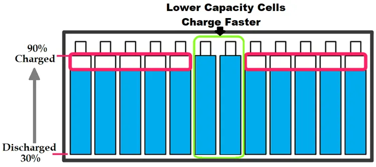
As the batteries in a pack get older few cells might be weaker than its neighboring cells. These week cells will be huge problem since they will charge and discharge faster than a normal healthy cell. While charging a battery pack with series cells the charging process should be stopped even if one cell reaches the maximum voltage. This way the if two cells in a battery pack get week they will charger faster and thus the remaining cells will not be charged to it maximum as shown below.
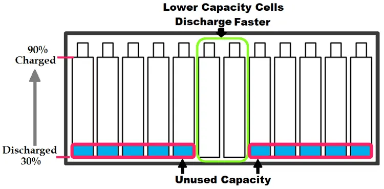
Similarly in the same case when the battery pack is being discharged, the weaker cells will discharge faster than the healthy cell and they will reach the minimum voltage faster than other cells. As we learnt in our BMS article the pack will be disconnected from load even if one cell reaches the minimum voltage. This leads to the unused capacity of the pack energy as shown below.
Accounting all the above possible disadvantages in consideration, we can conclude that a cell balancing would be mandatory to utilize the battery pack to its maximum efficiency. Still there are few applications where initial cost should be very low and battery replacement is not a problem in those applications cell balancing could be avoided. But in majority of applications including electric vehicles, cell balancing is mandatory to get the maximum juice from the battery pack.
Types of Battery Cell Balancing
Cell balancing techniques can be broadly classified into the following the four categories which are listed below. We will discuss about each category.
- Passive Cell Balancing
- Active Cell Balancing
Passive cell balancing method is the simplest method of all. It can be used in places where cost and size are major constraints. The following are the two types of passive cell balancing.
Charge Shunting
In this method a dummy load like a resistor is used to discharge the excess voltage and equalize it with other cells. These resistors are called as bypass resistors or bleeding resistors. Each cell connected in series in a pack will have its own bypass resistor connected through a switch as shown below.
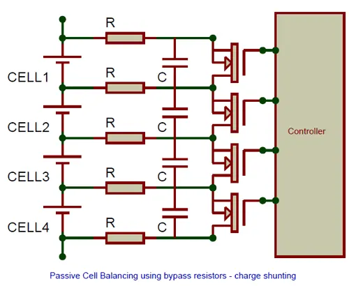
The sample circuit above shows four cells each of which is connected to two bypass resistors through a switch like MOSFET. The Controllers measures the voltage of all the four cells and turns on the mosfet for the cell whose voltage is higher than the other cells. When mosfet is turned on that particular cell begins to discharge through the resistors. Since we know the value of resistors we can predict how much charge is being dissipated by the cell. The capacitor connected in parallel with the cell is used to filter voltage spikes during switching.
This method is not very efficient because electrical energy is dissipated as heat in the resistors and the circuit also accounts of switching losses. Another drawback is that the entire discharge current flows through the mosfet which is mostly build into the controller IC and hence the discharge current has to be limited to low values which increases the discharging time. One way to overcome the drawback is to use an external switch to increase the discharge current as shown below-
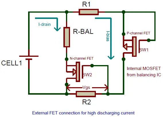
he internal P-channel MOSFET will be triggered by the controller which causes the cell to discharge (I-bias) through the resistors R1 and R2. The value of R2 is selected in such a way that the voltage drop occurring across it due to the flow of discharge current (I-bias) is enough to trigger the second N-channel MOSFET. This voltage is called the gate source voltage (Vgs) and the current required to bias the MOSFET is called as biasing current (I-bias).
Once the N-channel MOSFET is turned on the current now flows through the balancing resistor R-Bal. The value of this resistor can be low allowing more current to pass though it and thus discharging the battery faster. This current is called as drain current (I-drain). In this circuit the total discharge current is the sum of drain current and bias current. When the P-channel MOSFET is turned off by the controller the biasing current is zero and thus the voltage Vgs also gets zero. This turns off the N-channel MOSFET leaving the battery to get ideal again.
2. Active Cell Balancing
In Passive cell balancing the excess charge was not made used of, hence it is deemed to be inefficient. Whereas in active balancing the excess charge form one cell is transferred to another cell of low charge to equalize them. This is achieved by utilizing charge storing elements like Capacitors and Inductors. There are many methods to perform Active cell balancing lets discuss the commonly used ones.
Charge Shuttles (Flying Capacitors)
This method utilizes capacitors to transfer charge from high voltage cell to low voltage cell. The capacitor is connected through SPDT switches initially the switch connects the capacitor to the high voltage cell and once the capacitor is charged the switch connects it to the low voltage cell where the charge from the capacitor flows into the cell. Since the charge is shuttling between the cells this method is called as charge shuttles. The below figure should help you understand better.
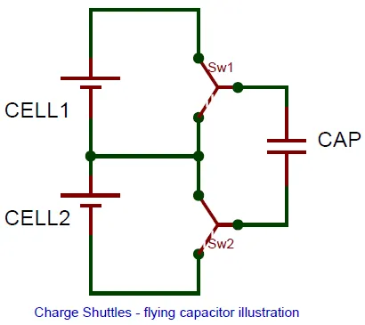
These capacitors are called the flying capacitors since the fly between the low voltage and high voltage cells carrying chargers. The drawback with this method is that charge can be transferred only between adjacent cells. Also it takes more time since the capacitor has to be charged and then discharged to transfer the charges. It is also very less efficient since there will be loss in energy during the charging and discharging of the capacitor and the switching losses also have to be accounted.