Morphing Operation on a geometry and FE model by using ANSA
AIM :
To Performing a morphing operation on a given component & FE Model as well. All should done in ANSA.
OBJECTIVES :
To Perform a morphing operation on a given geometry by using Box & Direct Method Morphing.
To Perform a morphing operation on a FE Model by using Direct Design Method.
Uses of Morphing Techniques in various industries.
GIVEN CAD MODEL :
Open a ANSA software, followingly importing the appropriate model file by using Open Gui option. Once, model file is imported in proper manner, it will showing the component from the graphical area like as shown in below.
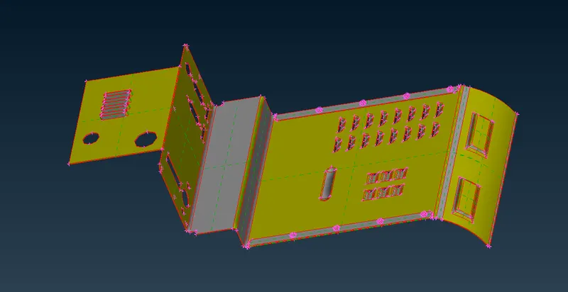
As we notice from given model macros or surface had not been attached to each other. Inorder to attach the macros to each other, we have use "Topo" option under where the "Topology" module & "Faces" sub modules.
By default, Topo option have some tolerance value, if the selected two cons distance between is less than the tolerance value, by result it will be pasted to each other.
After done the topo, it will look like as shown in below image.
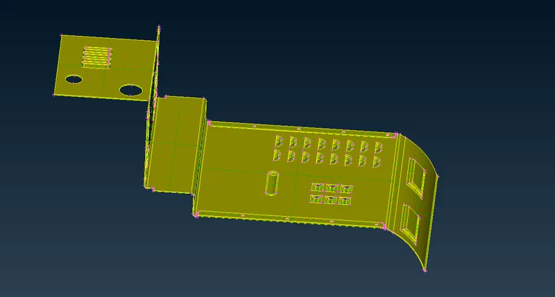
PROCEDURE FOR ATTAINING THE OBJECTIVES :
I) Morphing on a parent geometry :
We will use two types of methods for morphing on the parent geometry. There are
i) Morphing the component with Morph box.
ii) Morphing the component without Morph box.
i) Morphing the component with Morph Box :
Inorder to change the shape of particular part in the parent geometry. First of all, we have to create a Morphing box for that particular part.
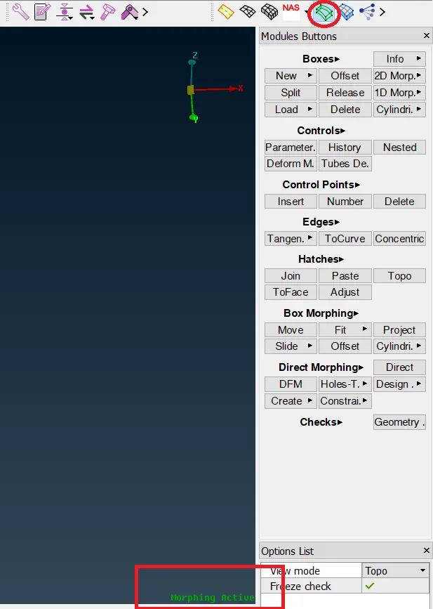
Inorder to perform morphing operation, we have go to "Morphing" modules. Once we open the Morph module, as we can see from bottom right corner on the graphical window which is showing "Morphing Active" like as shown in below image.
1) Creating the Morphing Box:
Select the "New" & followingly choose the "Ortho" option fromwhere "Morph" module & "Boxes" sub modules.
By default, FE Entities had been selected, we have to select the Geometry mode instead of FE Entities. Because, in this case we have morphing only on geometry.
Followingly, select the surface which we gonna capturing with morph box.
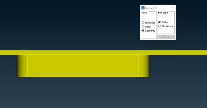
Once done the selection, make sure click middle mouse button for which proceeding with next step which is box generation.
After click the middle mouse button, a box will created around the selected surface like as shown in below image.
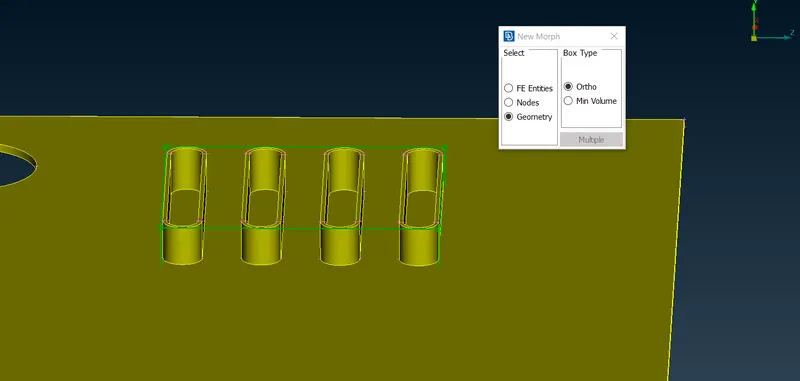
Similarly, we have to follow the same procedure to which creating the morph box for this areas like as shown below
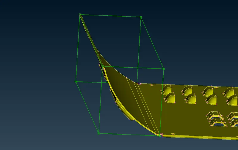
Once again, we follow the same procedure to which creating the morphing box for this areas like as shown in below.
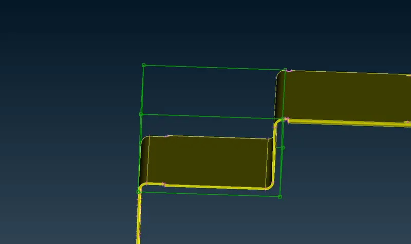
Once we created the box, what are surface are occupied at inside the box, All should be dependent to that particular box nodes, which means If change any one of the nodes, by results attached surfaces to that node are also be change the shape respect to that particular node.
2) Change the design shape :
Inorder to change the design shape by using morph box, go to select the "Move" option from where "Box Morphing" sub module & "Morphing" module.
Once, we select the Move option, One new window has pop up like as shown in below. A Few main options are available in the box which is "Entities" & "Nodes".
If we select the "Entities" option, Click any one of the box edge line, by result nodes has been selected.
If we select the "Nodes" option, we have to keep the cursor on the nodes & then click to select the node individually.
Select the "MV Free" option for which move the nodes along three dimensional direction.
In this case, we select the top four nodes to morph the geometry shape as per our new design requirement.
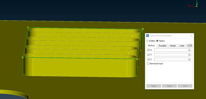
After done the morphing, we got a new shape little extension like as shown in below image.
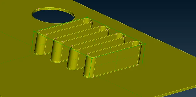
Similarly, we got a new shape like as shown in below by using same procedure what we saw in previously.
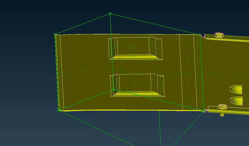
Again, we use same procedure to got the new shape like as shown in below.
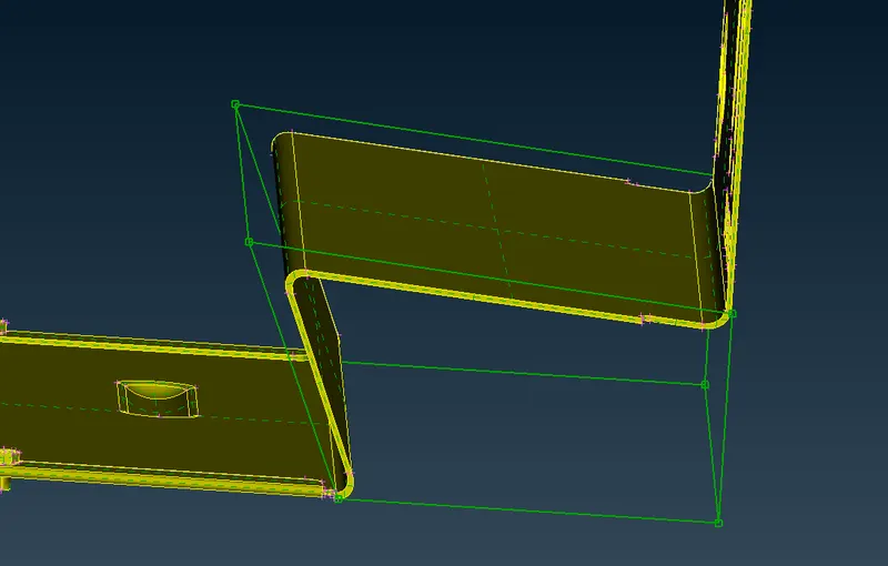
ii) Morphing the component without Morph Box :
Inorder to morphing the component without creating the morphing box. First of all, we select the "DFM" option from where "Direct Morphing" sub module & "Morph" module.
Once we select the DFM Option, new tab will open like as shown in below image at left side.
By using "DFM" option, we can able to morph the geometry part & FE model as well. Since, we morph the geometry alone, so we choose Geometry instead of FE Entitties. Followingly, select the entities which we gonna translate on the surface like as shown in below image. Click middle mouse button or just click next option for which proceed the next stage.
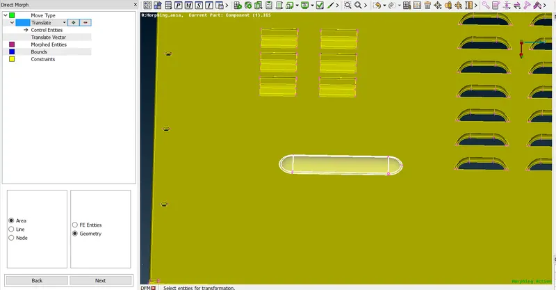
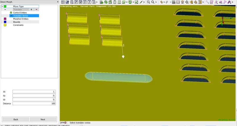
Select the vector direction for which selected entity will move along that direction and also provide the distance is 100 like as shown in below. Click the next option to which proceed the next stage.
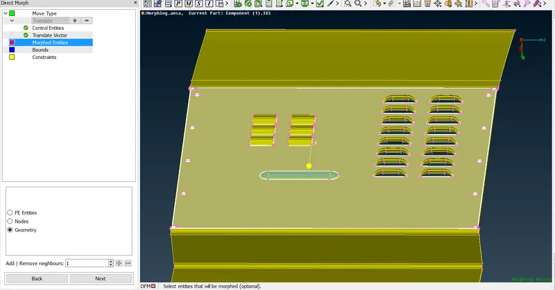
Select the Morphing Entities at top & bottom which are around around the stamp surface like as shown below image. Because, when Stamp will move at along the vector direction, a selected surface are try to justing itself.
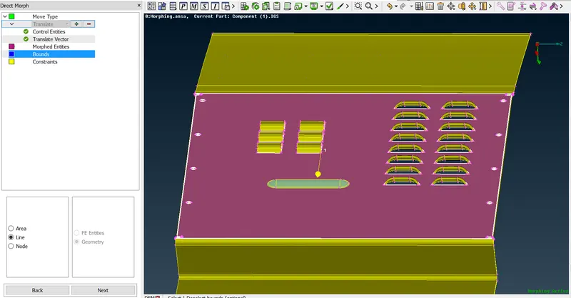
For Bounds We don't need to select anything, because it's an optional. Click to next.
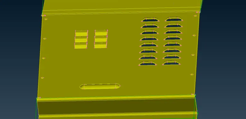
Click Apply & Accept. As we see from the below image, a stamp has moved as per vector direction & distance.
Apart from Translate option, we can able to use Rotate, Transform, Scale, Offset, Edge Fit, Surface Fit, Align & Sweep option on the same feature.
II) Morphing on FE Model :
Inorder to performing a morphing operation on a FE model. First of all, We have to extract the middle surface from the parent geometry by using offset face option. Before generating mid surface, make sure we have check the parent component for which any geometrical errors are happens or not.
Discritize the entire mid surface into finite number of elements. Inorder to morphing the FE model, make sure we have to release finite elements from the middle surface, then only we will able to see the FE model when we open the morph module.
By using Design Change Option :
Select the "Design Change" option from where "Direct Morphing" sub module & "Morphing" module.
This option will only allows to morph on FE Entities. By using this option, we change the features like stamps, ribs, shell etc..
i) Slide the feature :
First of all, select the "Design Change" option, followingly choose Feature with slide. Select the feature which we want slide like as shown in below.
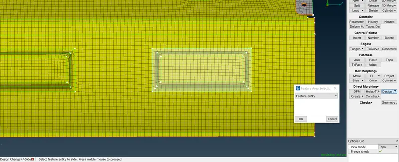
Once selection is done properly, click middle mouse button to conform the seletion. Once selection is conformed, selected areas will change into red in colour like as shown in below.
Also, Local cordinate had been created at where centre of gravity of the selected area.
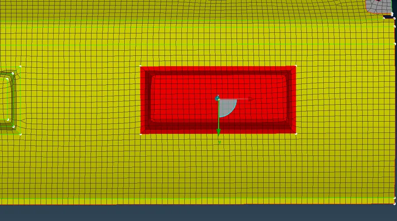
By using local coordinate to get move the feature as per our requirement. If we click the any one of the axis, then feature will move along that particular axis with either in positive or negative direction. Similarly for remaining two coordinate axis.
Change option list like "Free" for movement type & Projection direction, check the improve mesh and then keep as it as default setting.
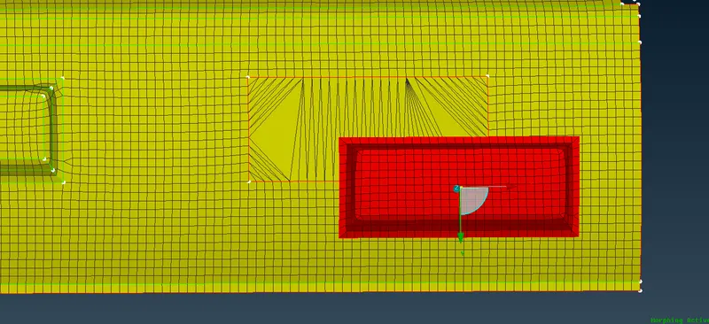
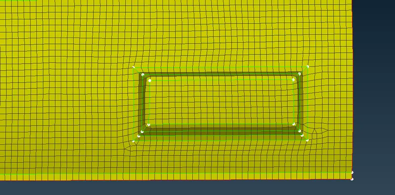
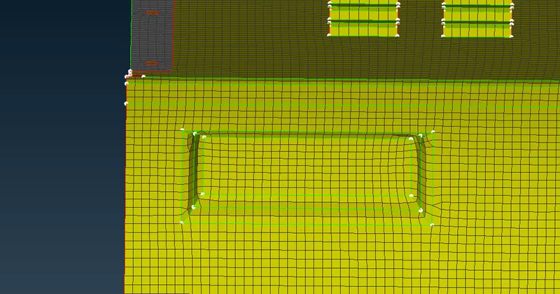
Once, we findout the appropriate location, click the "Save as Dc Feature" for conformation. After that, mesh has automatically adjusted around the feature as shown in below.
ii) Scale the feature :
Similarly steps we will follow as we saw in previously, but one thing we have change it on options list.
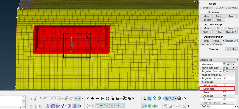
Here below image, we will be scaling the stamp feature as per our requirement.
Select the feature which we want to be scaling & click to conformation. Check the "Scale mode", after that local coordinate axis has been changed for scaling like as shown in below image.
By using local coordinate axis which is x,y & z to change the size of the feature as per requirement.
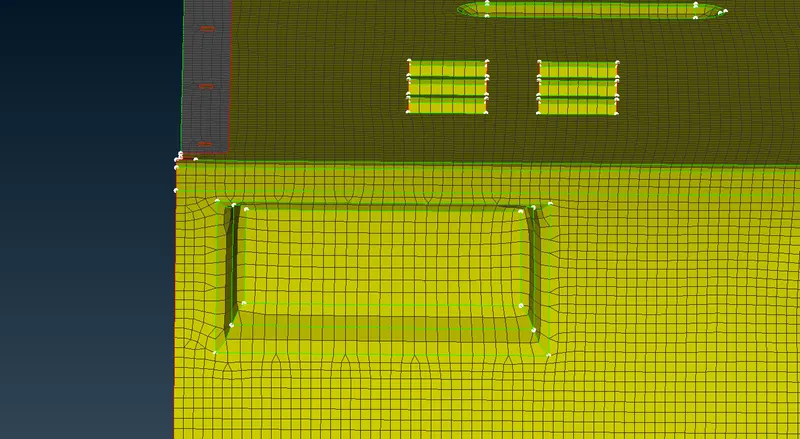
Once done the scaling on the feature, it will looks like as shown in below image.
iii) Rotate the feature :
First of all, select the "Design Change" option, followingly choose Feature with slide. Select the feature which we want rotate like as shown in below.
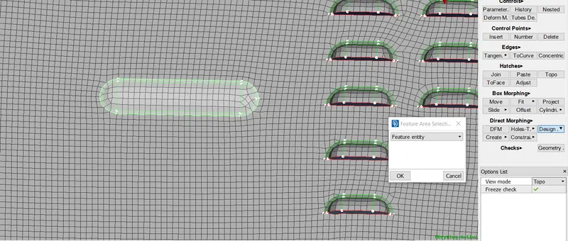
Click to conform the selection. Inorder to rotate the feature, we have to click on the local coordinate angle representation and then press the space button from the key board, provide the angle for which rotate the feature. Click middle mouse button to conform.
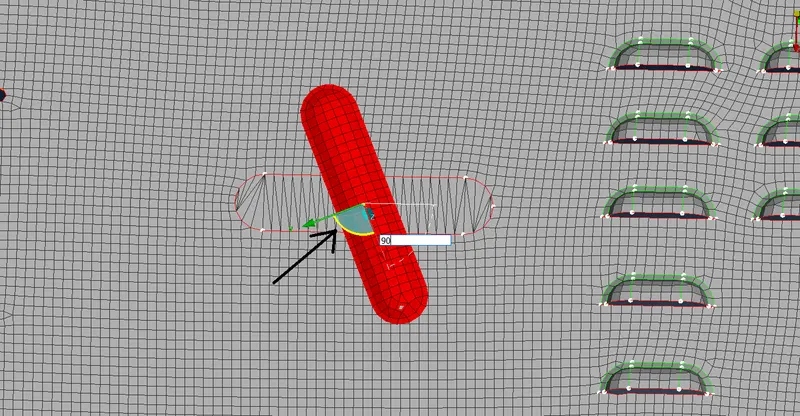
After rotate the feature, it will look like as shown in below. Mesh will automatically adjusted by itself.
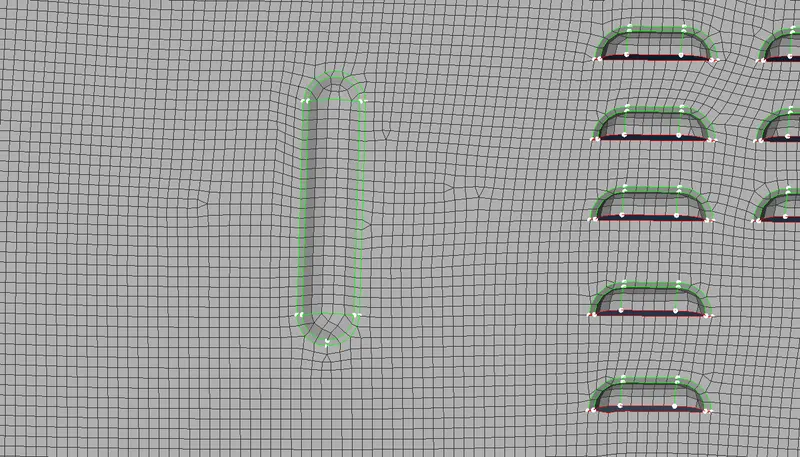
Copying the Features :
Select the "Design change" option, followingly choose feature with copy option. Select the feature which we want to copy like as shown in below.
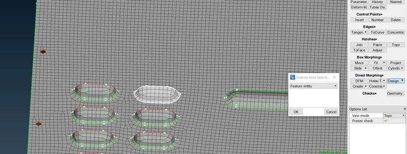
In the options list, we have change into " Follow Path" for Movement type instead of "Free". Similarly, we have change "Points" for Defines path on & Glide for Movement on Path.
Provide 3 for number of steps we want copying the same feature .
Select the path by using points like as shown in below image. We have to drag the feature by using local coordinate axis.
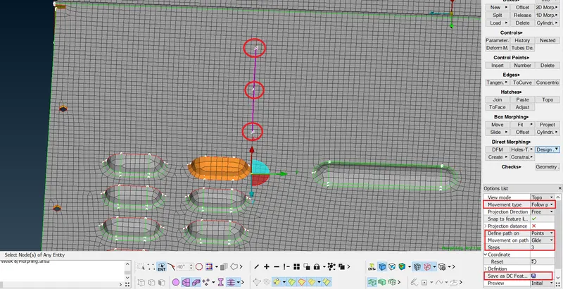
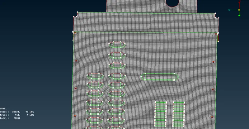
After Copying is done, we can able see from the below image, features are created as per our imputs.
IV) Uses of morphing in Various Industry :
Basically, it is a design change terminomogy on both geometry & Finite Element Model as well. This has been done without any numerical inputs.
Most of the Automotive Industries are using Morphing technique to achieve design modification from Sedan car to Hatch back car like Hyundai Grand i10 (2013) Hatch back model & Hyundai Xcent (2014) Sedan Model apart from this most of automotive companies are used in similar morphing techniques to reduce work time & money .
In most of the aviation companies are try to findout the optimum Airfoil desgin with low drag force & High Lift force. Inorder to findout the optimum design, a person have to model atleast 1000 times, it's really hard to do in each simulations. By using Morphing techniques, we will able to change the design for FE Model alone without creating a new design. If any of design attains our requirement while perform an simulation, after that design engineer will come to create new model as per optimum FE model dimensions.
CONCLUSION :
Successfully done the morphing operation on both in given geometry as well as Finite element model by using some few morphing methods available at ANSA to which attend the new shape as per our requirement.
LEARNING OUTCOME :
I Learned How to morphing on the geometry as well as FE model by using some few option.
I Learned How to Create a Morph box & how to change the shape of the compoenent by using Morph box.
I Learned How to Morph by using Direct Morphing method, Design change Morphing method and then DFM option