Studying effect of Mass scaling in dynamics analysis in Ls Dyna
Objective:
- To introduce mass scaling Technique to reduce the computational time for the analysis and
- The limit for the mass scaling is restricted to 8% and simulation as to be completely stability
Introduction:
- Timestep Significance
In the simplest case (small, deformation theory), the time step is controlled by the acoustic wave propagation through the material
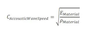
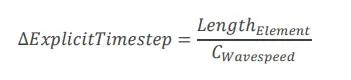
In explicit integration, the numerical stress wave must always propagate less than one element width per time step. The time step of an explicit analysis is determined as the minimum stable time step in any one deformable finite element in the mesh. The above relationship is called the Courant-Friedrichs-Lewy (CFL) condition and determines the stable time step in an element.
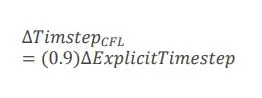
The CFL condition requires that the explicit time step be smaller than the time needed by the physical wave to cross the element. 0.9 is the timestep scale factor (TSSFAC).
Based on the conditions, the time step can be increased to provide faster solution times by artificially increasing the density of the material by using technique like ( mass scaling, lowering the modulus, or by increasing the element size of the mesh)
- Mass scaling
Mass-scaling is a term that is used for the process of scaling the element’s mass in explicit simulations to adjust its timestep. The primary motivation is to change (usually increase) the global compute timestep which is limited by the Courant’s stability criteria Mass scaling is very useful and directly increases the timestep. The concept is simple, Larger Timestep = Lower Solution Time. The manual form of mass scaling is done independently of the automatic mass scaling invoked with DT2MS in *CONTROL_TIMESTEP.
*CONTROL_TIMESTEP: Conventional mass scaling (CMS) (negative value of DT2MS): The mass of small or stiff elements is increased to prevent a very small timestep. Thus, artificial inertia forces are added which influence all eigenfrequencies including rigid body modes. This means this additional mass must be used very carefully so that the resulting nonphysical inertia effects do not dominate the global solution.
Two different types of mass-scaling using the DT2MS parameter from *CONTROL_TIMESTEP
- Negative DT2MS: Mass is added to only those elements whose timestep would otherwise be less than TSSF*(DT2MS). When mass scaling is appropriate.
- Positive DT2MS: Mass is added or taken away from elements so that the timestep of every element is the same. there is no advantage to using this method over the negative DT2MS method and I find it harder to rationalize.
If stability is a problem with the default TSSFAC of 0.9, try 0.8 or 0.7. If you reduce TSSFAC, you can increase |DT2MS| proportionally so that their product, and hence timestep, is unchanged. TSSFAC doesn’t affect the mass scaling percentage.
Mass scaling is no free lunch. For dynamic systems, added mass can affect the response of the system. It is just something to monitor and make an engineering judgment about its effectiveness; time savings versus potential detrimental effects. Increasing the mass too much may cause severe penetration problem and increase the dynamic effect significantly. The results may not be acceptable. In this case, the mass scaling is restricted up to 8%.
Procedure:
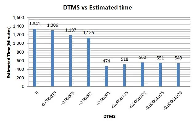
Since DTMS and TSSFAC are the important parameters is the *CONTROL_TIMESTEP card that affects the timestep and the runtime of the simulation, so we will change these values in each iteration to obtain a optimize runtime with a stable solution and to make sure mass scaling doesn’t go beyond 8%
- Iteration 1: *CONTROL_TIMESTEP card is not implemented (No mass scaling)
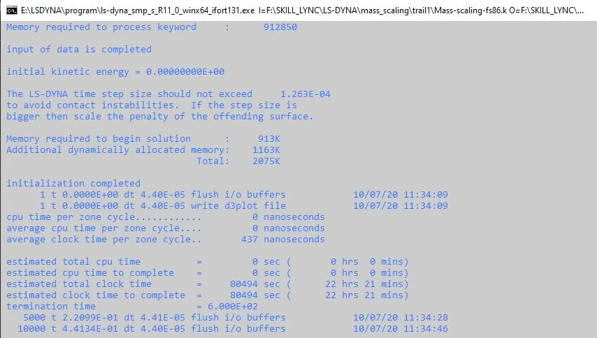

- Iteration 2: *CONTROL_TIMESTEP card is implemented with the default value of DTMS and TSFC
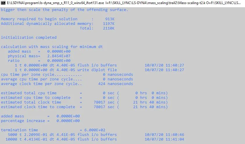

As we can notice by introducing *CONTROL_TIMESTEP the run time have reduced a little, so in the next iteration we will try to increase the DTMS value and see how the run time changes
- Iteration 3: *CONTROL_TIMESTEP card is implemented with increases in DTMS and constant TSFC
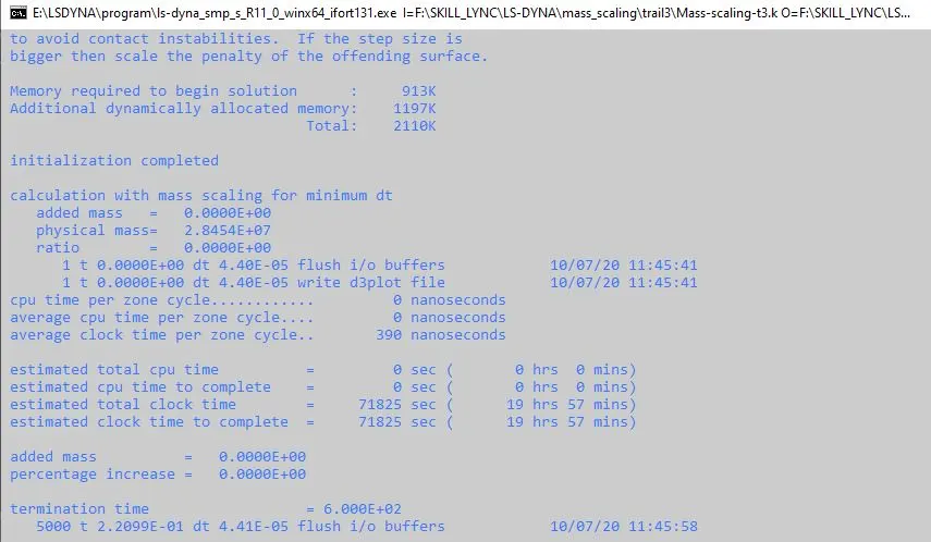

By Increasing the DTMS value and trend of Estimated time (to complete) is decreases, so we will further increase the DTMS value
- Iteration 4: *CONTROL_TIMESTEP card is implemented with increases in DTMS and constant TSFC
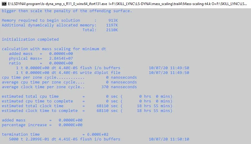

As expected the Estimated time reduced. But they were no mass added to the system and since we have the liberty to have mass percentage up to 8% we can still increase DTMS value to reduce the estimated time.
- Iteration 5: *CONTROL_TIMESTEP card is implemented with increases in DTMS and constant TSFC
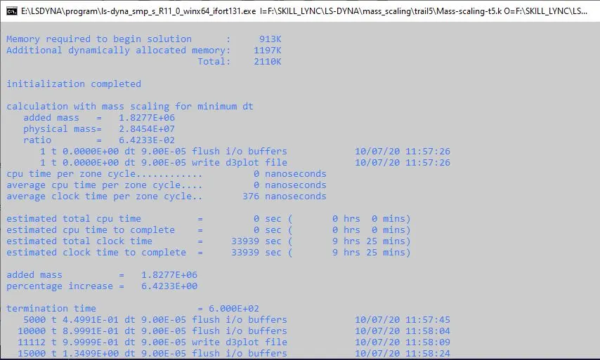

The estimated time (To complete) has reduced drastically around 50% of the time and eventually, the mass is also added to the system above 6.4% which is acceptable for us.
- Iteration 6: *CONTROL_TIMESTEP card is implemented with decreased in DTMS and constant TSFC
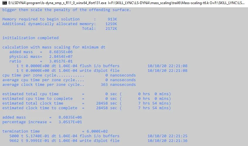

By decreasing the DTMS value and trend of estimated time (to complete) is decreases but if we notice the mass percentage is 30% which way more than 8% which is not acceptable. So scale of decreasing value of DTMS should be less.
- Iteration 7: *CONTROL_TIMESTEP card is implemented with decreased in DTMS and constant TSFC
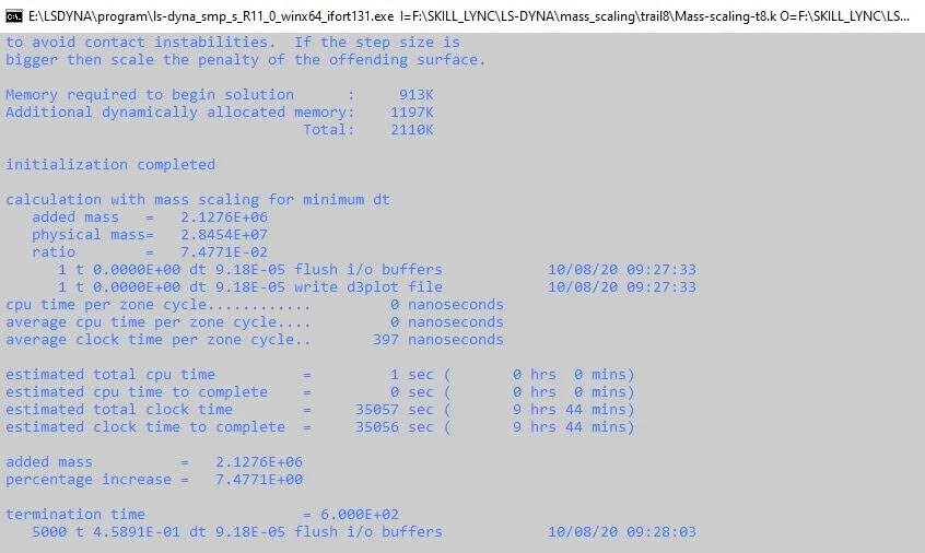

By decreasing DTMS value in a smaller scale, we were able to control the increases in mass-scale percentage, but compared to Iteration 5 the estimated time as reduced a little and even though we still have reached the mass scale limit we can still decrease the DTMS value
- Iteration 8: *CONTROL_TIMESTEP card is implemented with decreased in DTMS and constant TSFC
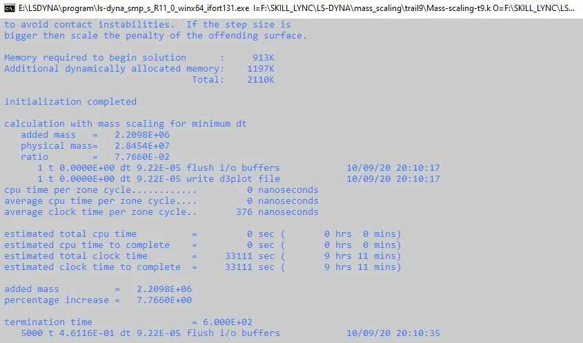

By decreasing the DTMS value we were able to reduce the estimated time and eventually the mass percentage as also increased but still the mass percentage hasn’t reached the limit.
- Iteration 9: *CONTROL_TIMESTEP card is implemented with decreased in DTMS and constant TSFC
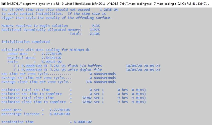

As expected the estimated time (to complete) has reduced by decreasing the DTMS value and If we notice the mass percentage is 8% which have reached it limit value ,Because more than 8% of the mass is not accepted, So further decreases of DTMS will only increase and the mass percentage of the system.
- Iteration 10: *CONTROL_TIMESTEP card is implemented with the same value of DTMS from Iteration-9 and TSFC value is decreased
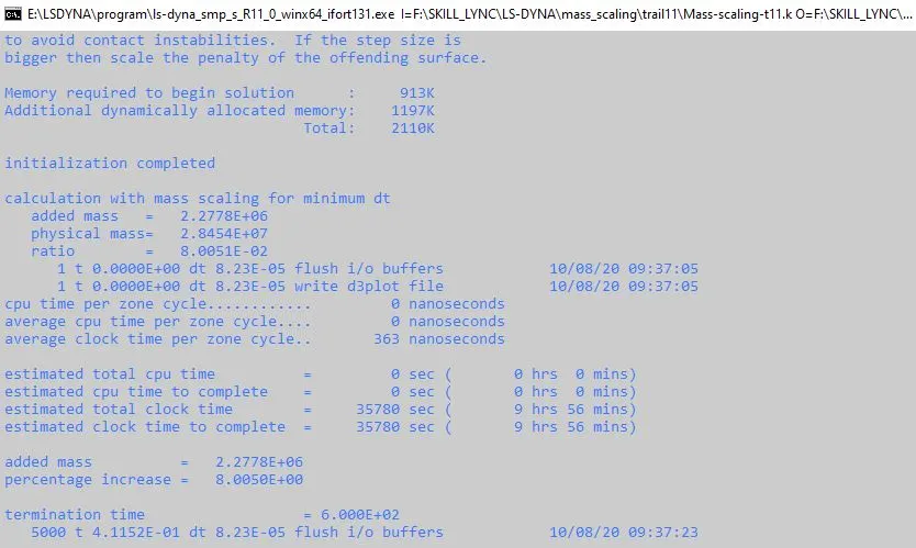

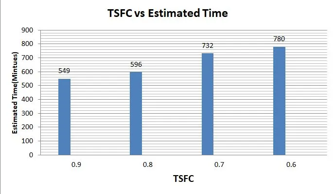
As we know the TSFC Parameter won’t affect the additional mass added to the system and that’s why the mass percentage as remained unchanged. But as we can see TSFC parameter affects the time step or estimated time and that’s why there is an increase in estimated time compared to the previous iteration.
- Iteration 11: *CONTROL_TIMESTEP card is implemented with same value of DTMS from Iteration-9 and TSFC value is decreased
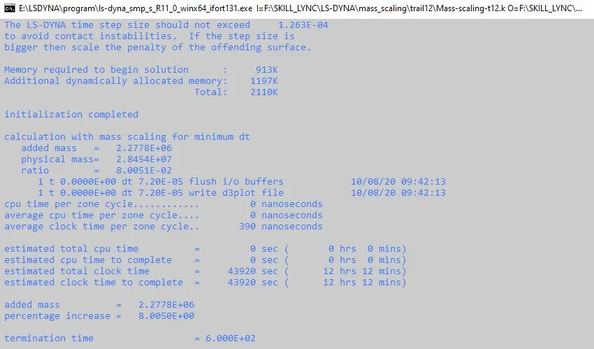

The trends are the same as the previous iteration as the TSFC value decreases and the Estimated time increases
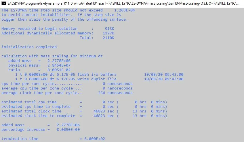
- Iteration 12: *CONTROL_TIMESTEP card is implemented with same value of DTMS from Iteration-9 and TSFC value is decreased

Implicit analysis
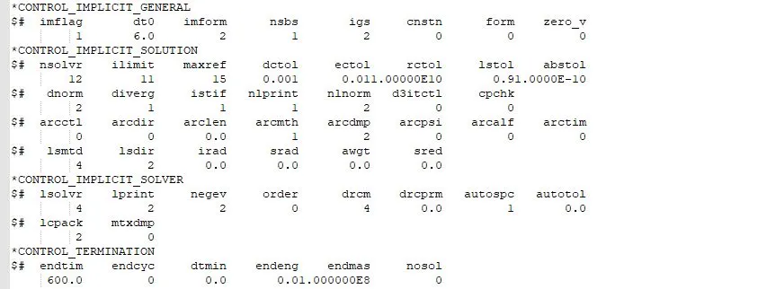
Now we will run this same file using an implicit solver.Additional control card is used to run this simulation in implicit solver.
Control card
1.*CONTROL_IMPLICIT_GENERAL
Activate implicit analysis and define associated control parameters. This keyword is required for all implicit analyses
- IMFLAG - Implicit/Explicit analysis type flag : 1- implicit analysis
- DT0 – Initial time step size for implicit analysis (Termination time/100): 6
- IMFORM - Element formulation flag for seamless spring back: 2 retain original element formulation (default)
2.*CONTROL_IMPLICIT_SOLUTION
Use of these cards to specify whether a linear or nonlinear solution is desired
- NSOLVER – Solution method for implicit analysis: 12 For Non-linear problem
- ILIMIT-Iteration limit between automatic stiffness reformations: 11
- MAXREF- Stiffness reformation limit per time step: 15
- DCTOL- Displacement relative convergence tolerance: 001
- DNORM- Displacement norm for convergence test: 2 (Increment as a function of total displacement)
3.*CONTROL_IMPLICIT_SOLVER
The linear equation solver performs the CPU-intensive stiffness matrix inversion
- LSOLVR- Linear equation solver method: 4 (uses solve the simulation with single precision which consequently saves run time rather than going for a double-precision solver)
Results:
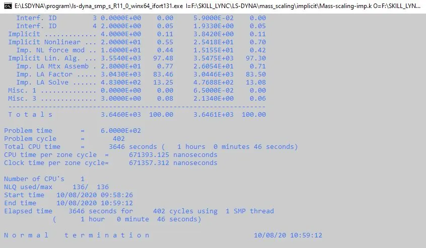
- Its shows that the implicit method took 60 minutes to solve.
- If you notice the initial timestep is 6 and we have used constant timestep formulation because our termination time is very large
- Basic thumb rule to calculate initial time step is DT0 = termination time / 100 i.e 600/100
- And this value of the initial time step DT0 is defined in *CONTROL_IMPLICIT_GENERAL
Again, while accounting for accuracy, The simulation time and timestep in implicit is mainly controlled using *Control_Implcit_Auto card using parameters like ITEOPT, ITEWIN, DTMIN and DTMAX by defining the iteration and timestep limits
Conclusion :
- Using the Mass scaling Technique we reduce the simulation time by adjusting timestep which is limited by the Courant's stability criteria.
- We noticed how the DTMS and TSFC parameters affect the simulation run time and how the DTMS value affects mass scaling and it evidently proved TSFC values don’t affect the mass scaling value.
- Implicit and Explicit analysis differ in the approach to time increments.
- In Implicit analysis, each time increment has to converge, but we can set pretty long time increments. Explicit on the other hand doesn’t have to converge each increment, but for the solution to be accurate time increments must be super small.
- Though the running time for implicit analysis is shorter than explicit analysis method, the because the timestep is defined larger in implicit compare to explicit analysis and we have used constant timestep formulation