Week 8- 3D Meshing
3D Meshing
Introduction on 3D Meshing:
3D elements are usually used to mesh volumes. They are derived from 2D elements that are used when the problem is unable to be simplified. 3D solid elements only account for translational displacements.
These elements are suitable for three-dimensional analysis. uses for solid parts and sheets of thickness more than 5mm, Transmission castings. engine blocks etc
Example- Tetra elements and hexa elements.
Tetra element is the 4 noded with 4 triangle faces are formulated in three-dimensional space with three degrees of freedom per node. These are the translational degrees of freedom in the X, Y and Z directions, respectively. In the figure Tetra element is shown for 4 nodes and 10 nodes.
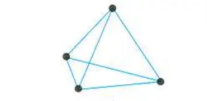
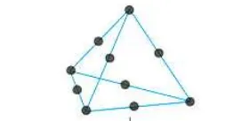
4 nodes Tetra element 10 nodes Tetra element
Hexa element is the 8 noded with 6 triangle faces are formulated in three-dimensional space with 6 degrees of freedom per node. These are the translational and rotational degrees of freedom in the X, Y and Z directions, respectively. In the figure the Hexa element is shown for 8 nodes and 20nodes.
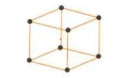
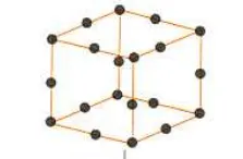
8 nodes Hexa element 20 Hexa Tetra element
1. Create Teramesh for Housing
2. For the given models, Create 3D tetramesh with 6mm element size.
Aim: To create the 3D meshing for the Housing by eliminating geometrical errors and considering the given element quality criteria using Hypermesh
Element Quality Criteria:
| S.No | Quality Criteria | Value |
| 1 | Target/Average length | (1) 5 & (2) 6 |
| 2 | Minimum Length | (1)2 |
| 3 | Maximum Length | (1)7 |
| 4 | Tetcolapse | (1) & (2) 0.15 |
Procedure:
1. Import Housing.stp in to Hypermesh
2. CAD Geometry clean up and topology
3. Defeaturing
4. Tria shell meshing
5. Tetra meshing
6. Check for tetcolapse
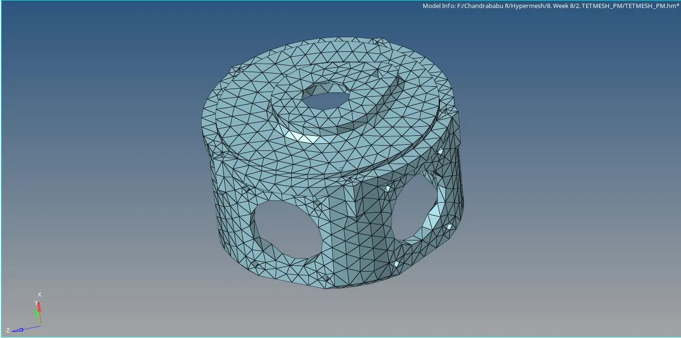
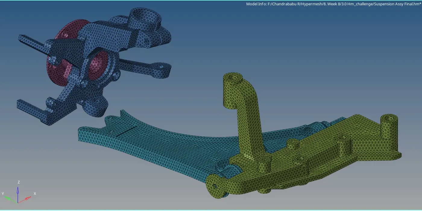
1. Import Housing.stp in to Hypermesh : Import the given Housing.IGS, TETMESH_PM and Suspension Assy.igs in to the Hypermesh Shown in the fig.1.1
Steps to import
a. lick on import geometry select type of file (IGS or Stp). If we want to open the Hypermesh file just click on the open model.
b. Browse the file and open. it will appear in the file selection table
c. click on import. Show in the fig 1.1A
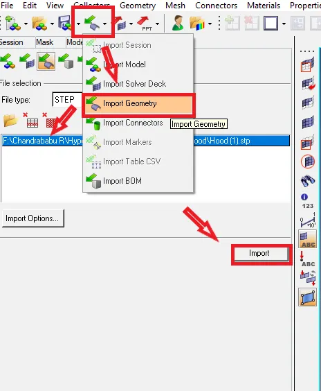
Fig.1.1A: Import file
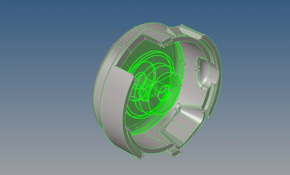
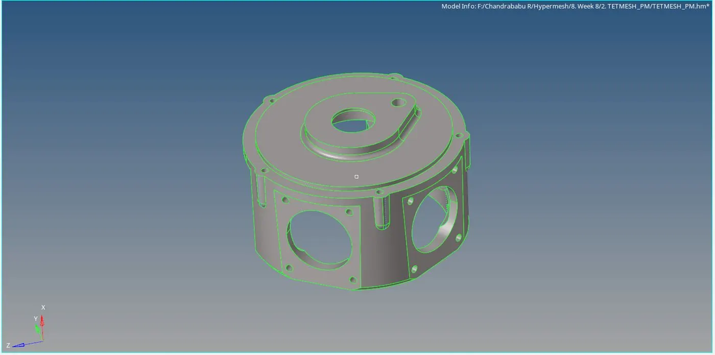
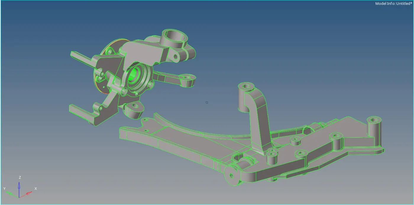
Fig.1.1: Imported file
2. CAD Geometry clean up and topology: In this step the given model undergoes geometry check. Where all the defects such as collapsed faces, cracks, free edges, T-edges are clear. In the fig.2.1 show description on surface.
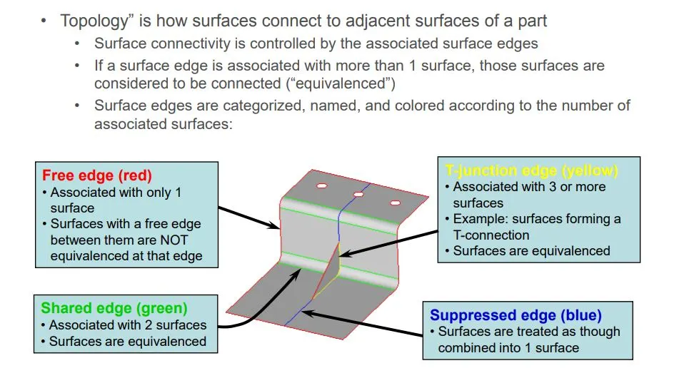
Fig.2.1: Description on surface.
Tools used in topology
Tools>Edge Edit Panel
A. Equivalence (multiple edges at a time): Search surfaces for pairs of free edges and combine into shared edges
B. Toggle (edge pair at a time): Select an edge; equivalences with other free edges found within a user specified tolerance
C. Replace (1 edge pair at a time): Select 2 edges to equivalence together. Control which edge to retain and which to move.
D. Geom>Surfaces>Ruled or Geom> Quick edit > filler surface or 2d> spline> surfaces only (to create missing surfaces) .
3) Defeaturing: Update the Criteria length as per given element Quality criteria which is Target/Average length 5 For Housing and 6 for other 2. Removing all unnecessary edges, fillet radiuses etc. also maintain distance between two edges or nodes not less than Minimum Length of 2 for housing and for other 2 models no minimum.
Tools used in Defeaturing
A. Toggle edge: Left-click a free edge (red) to make it shared (green), or a shared edge to make it suppressed (blue).
Right-click a suppressed edge to make it shared, or a shared edge to make it free.
In either case, the edge must meet the criteria for the type of edge you wish to change it to. For example, toggling a free edge to a shared edge requires the presence of a similar edge within the distance you specify in the tolerance field.
B. Replace (1 edge pair at a time) Select 2 edges to equivalence together. Control which edge to retain and which to move.
C. Geom> Quick edit > filler surface (to create missing surfaces) .
4. Tria shell meshing:
Before meshing Assign given element Quality criteria in to hypermesh by Preferences>criteria file setting shown in Fig.5.1
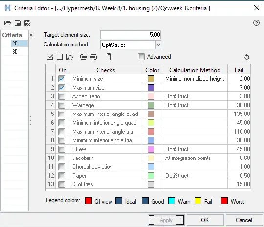
Fig.5.1: Quality Criteria
Start meshing Process by Automesh (2D>Automesh )
steps to mesh
a. Select surfaces for initial mesh and for remesh select elements.
b. select size and bias and select mesh size which is Target/Average length 5.
c. Select type of mesh as mixed (Quad, Tria, mixed, R tria etc) here tria is selected and click on alin and size in order to get proper mesh near features.
click on mesh or middle mouse button
Modify mesh flow by changenging surfaces to elements and select the elements then mesh . Make sure that while doing mesh all the element Quality criteria must be satisfied. Avid maxim opposite traits and. In fig.5.2, 5.3 and 5.4 show the mesh flow for all the models
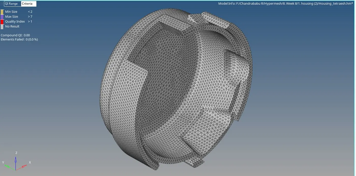
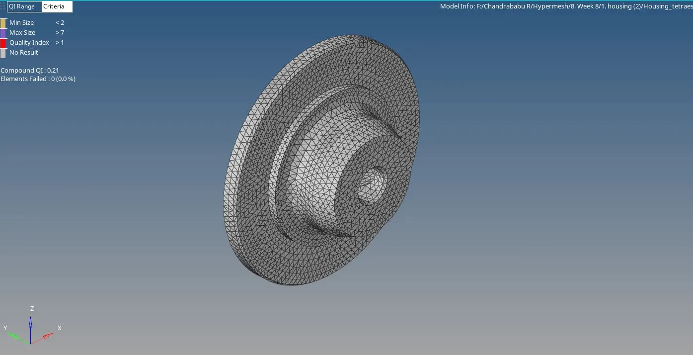
Fig.5.2: Housing 1
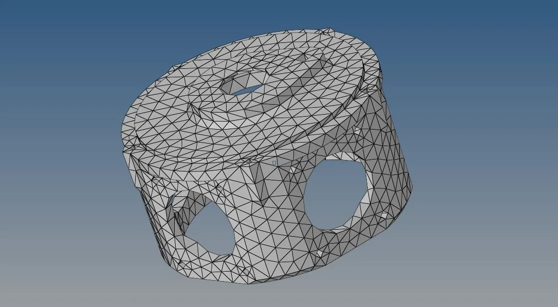
Fig.5.3: Housing 2
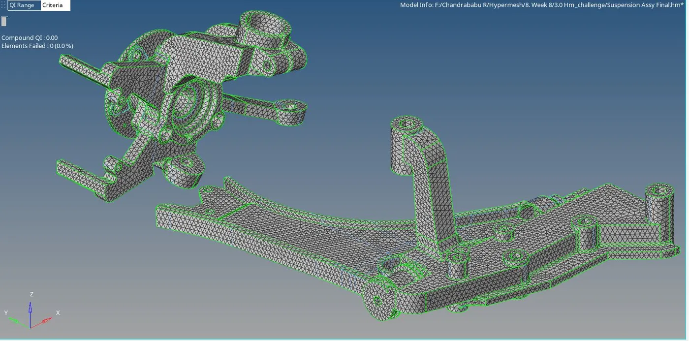
Fig.5.4: Suspension Assy
5. Tetra meshing: Tetra meshing is the 3D meshing process where the tetra elements are used to fill the volume. In hypermesh we can done tetra mesh by 3 methods
1. Tetra mesh panel: Convert 2d tria mesh to tetra mesh
2. Quick tetra mesh on close surface or components
3. Volume tetra mesh by selecting solids in the model.
here all the models are done by tetra mesh panel that is Convert 2d tria mesh to tetra mesh
Start Tetra meshing Process by Automesh (3D>Tetramesh > tetramesh )
steps to mesh
a. Select Elements option in panel and select elements for tetra mesh
b. Tick on Fix comp boundaries and update input shells
c. Click on the mesh or middle mouse button shown in the figure 6.1 panel for tetra mesh. We can tetra mesh in the figure 6.2

Fig.6.1: Tetra mesh anel
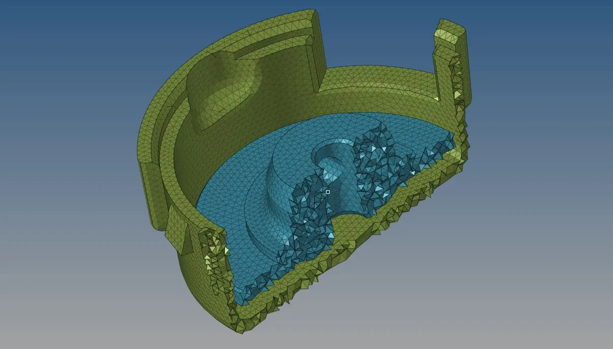
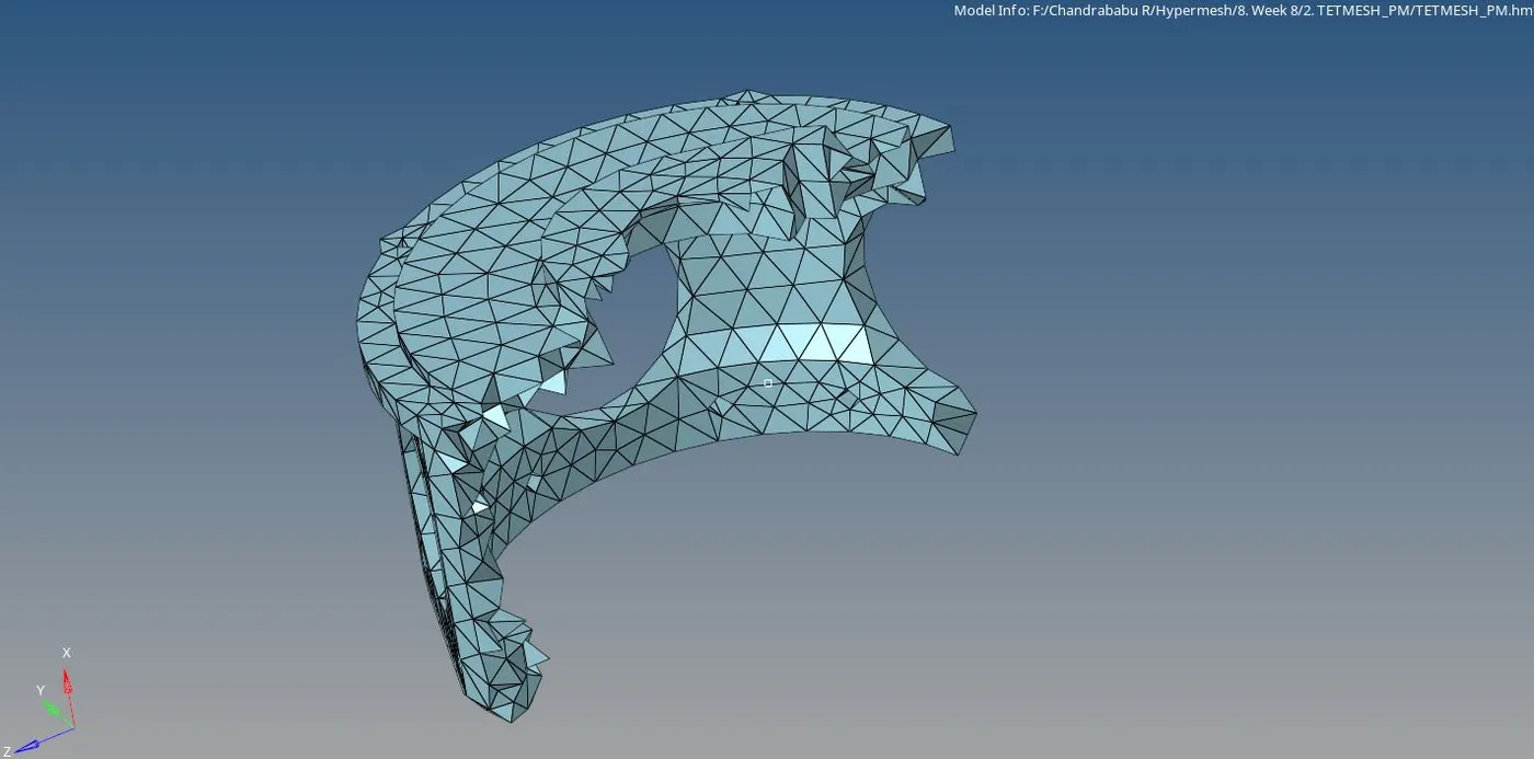
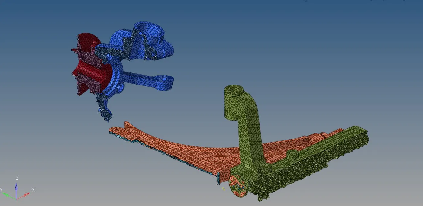
Fig.6.2: Tetra mesh
6. Check for tetcolapse: tetcolapse is the quality parameter for tetra elements.
It can be calculated by measuring the distance of a node from the opposite face, then each of the four values will be divided by the Square root of the opposite face’s area. The minimum of four resulting values is then normalized by dividing it by 1.24.
Generally tetcollapse can be calculated by the formula = Min of (h/√A) ÷ 1.24 Referred form
To clear the tetcolapse
1. Increase the minimum height of node from opposite plane until it reaches 0.15 as per the quality criteria
2. Remesh the component by providing remesh parameters shown in the fig. 6.3

Fig.6.3: remesh parameters
In the figure 6.4 shows tetcolapse for all models
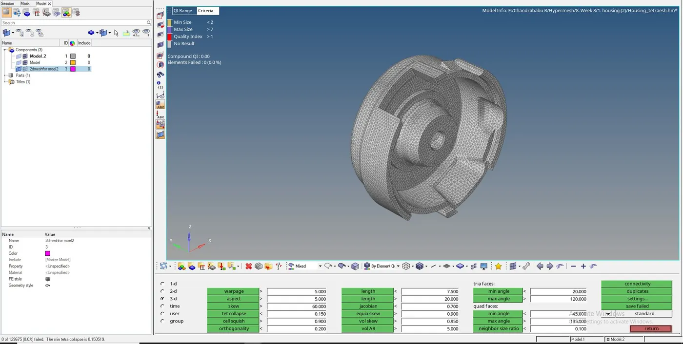
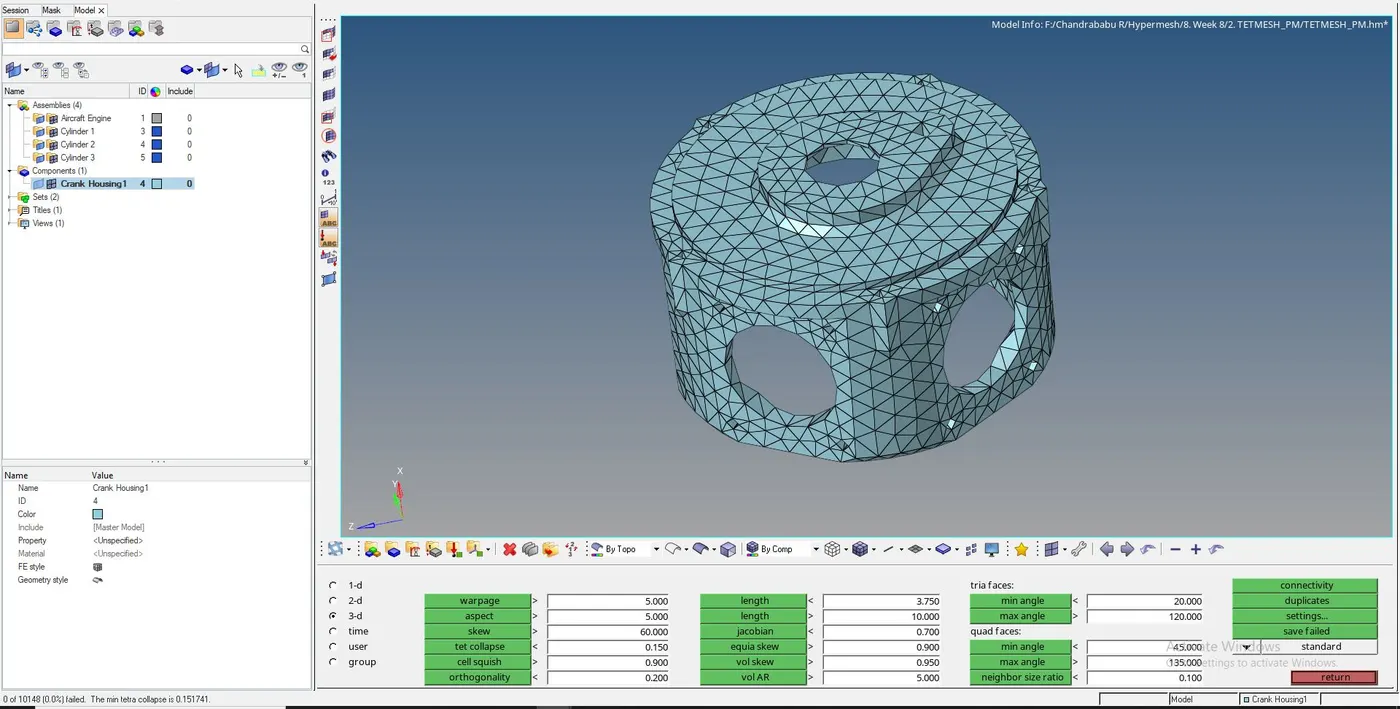
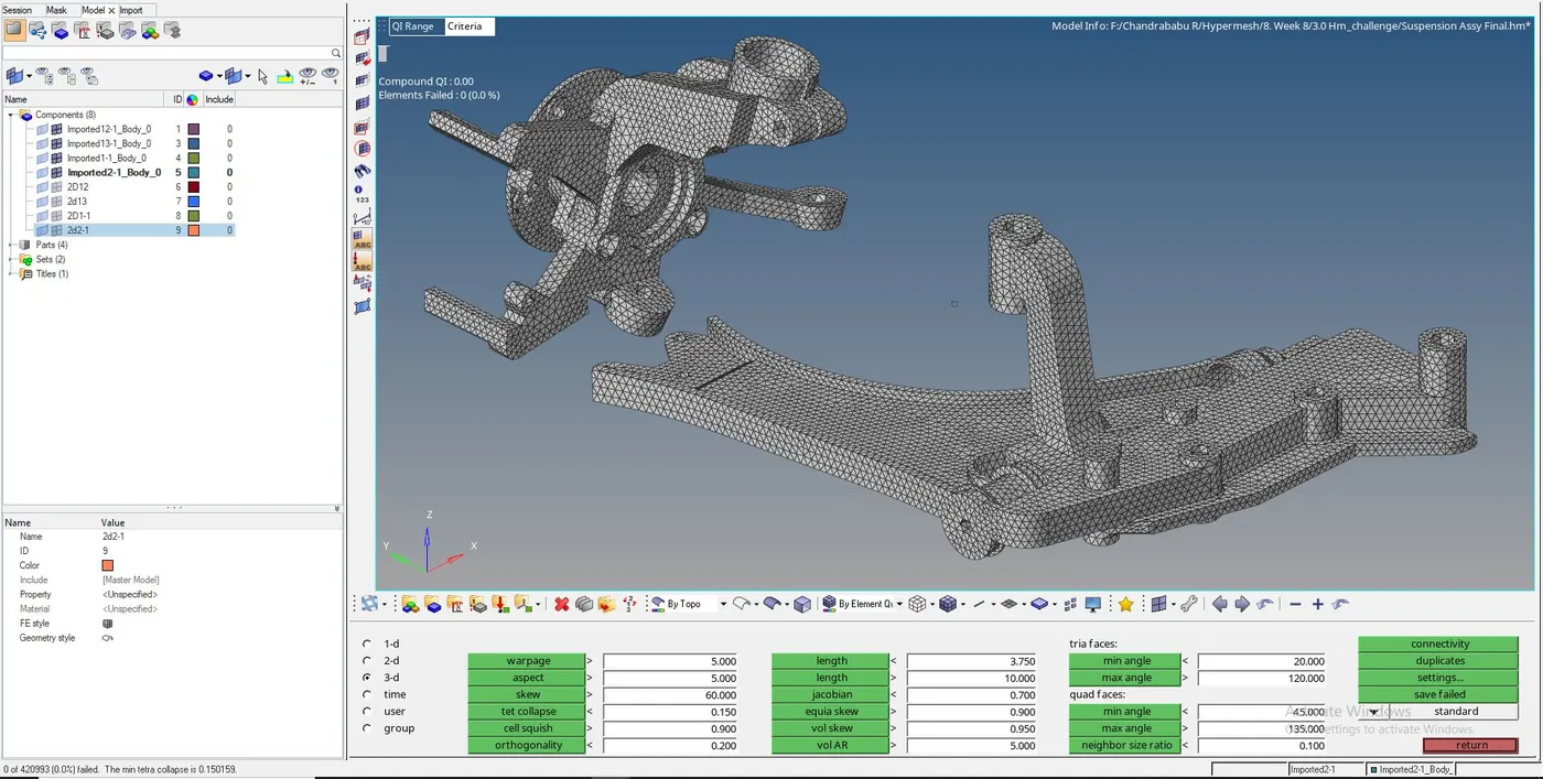
Fig.6.4:tetcolapse for all models
Result: Tetra meshing is done successfully for all 3 model by eliminating geometrical errors and considering the given element quality criteria using Hypermesh
In the fig. bellow show results images for all 3 models