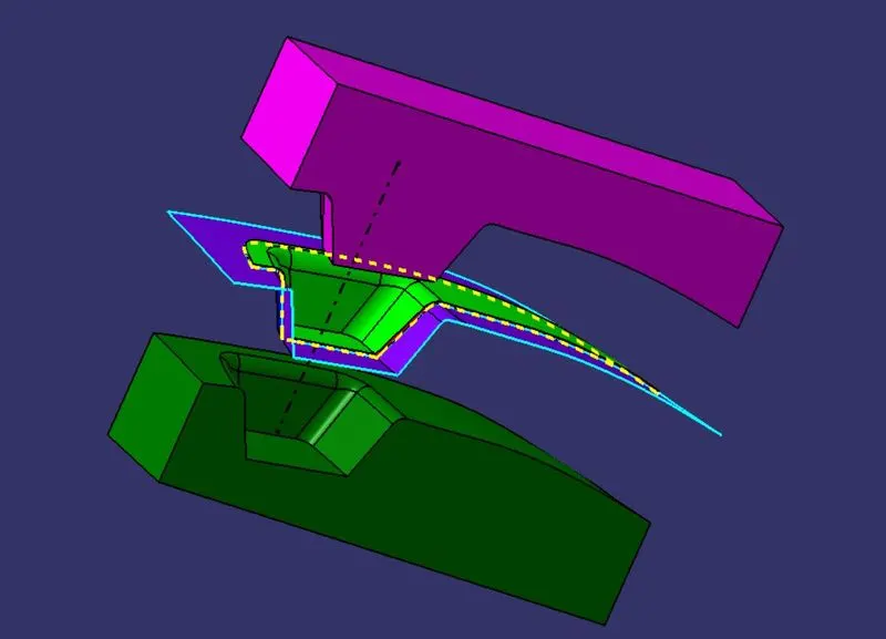
Week 8 - Challenge 6 - Core & Cavity Design
AIM :- To Create the Core and cavity blocks for the switch bezel.
Creation of Tooling Axis -
From given Class A surface I found that Z-direction is the best possible tooling direction. Then I have check this direction is clearing all surfaces along X and Y-direction or not.
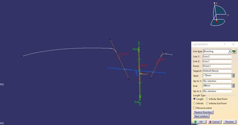
Creation of Y-Direction line-
By using intersection I have intersect Class A surface along Y-direction. Then make Y direction Clearing line.
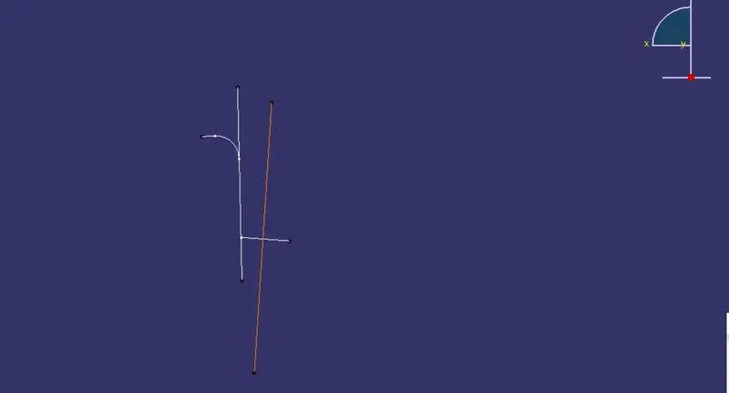
Creation of X-Direction line-
Same as Y-Direction line I have drawn X-Direction line.
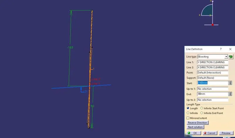
Main Tooling Axis -
By using Bisecting Line method I have created main tooling axis.
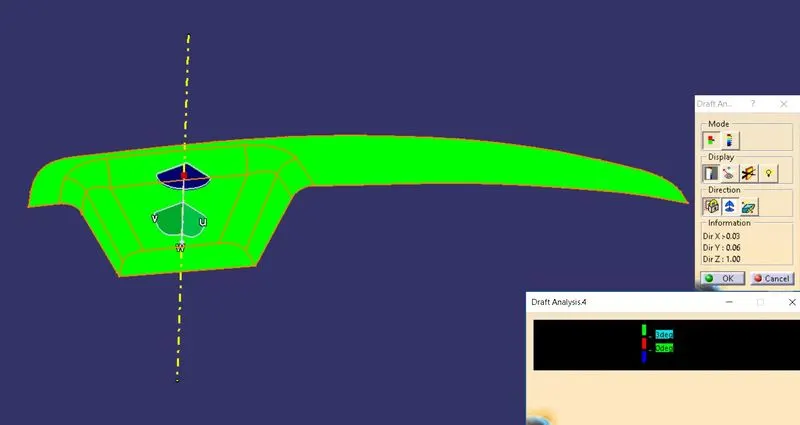
Draft Analysis on Class A Surface -
Draft Analysis on Solid Body -
The final solid part body has to be analyzed using Draft analysis. This is done to check if all the areas of the body are satisfying the draft angle which is 3 degrees.
A draft angle is a taper applied to the vertical walls of the injection-molded component to assist with releasing the part from the mold.
Draft angles are a required feature of injection-molded custom parts. A functional part for injection molding has to have draft angles that face both the cavity and core sides. This will reduce the risk of damage to the parts and ensure that they can be ejected from the machine.
The switch bezel body is checked using Analysis and images for it are shown below.
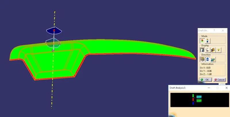
Isometric View -
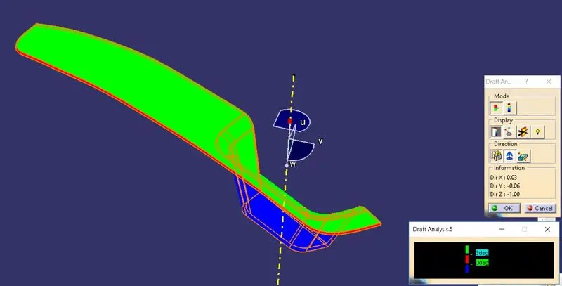
Front View -
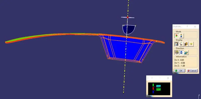
Side View -
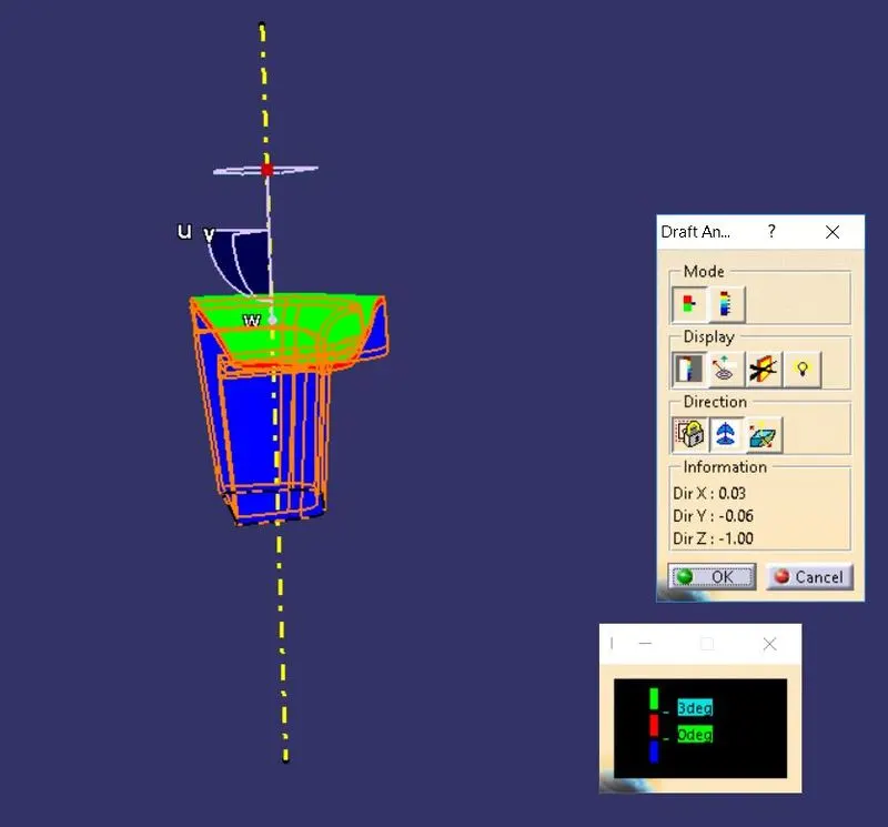
Top View -
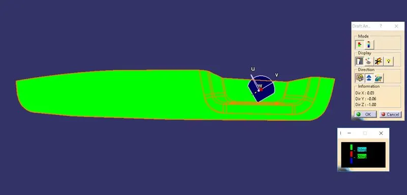
The Draft analysis of the component showed that the component is feasible to be molded without any issues.
Thus it satisfies all design and manufacturing criterias needed for a proper part.
CREATION OF CORE AND CAVITY BLOCK -
We have designed Switch Bezel component earlier. We will work on this CATpart file and create core and cavity blocks. We will use Class A , B and C surfaces from this file for creating parting surface , parting line and core-cavity block.
- CREATION OF PARTING SURFACE -
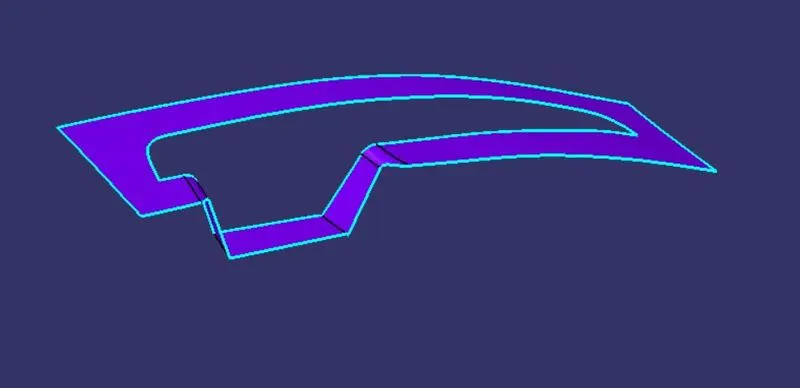
Generally injection mold has two major components the movable half and the fixed half, during the injecction molding process, these two halves are pressed tightly and formed a sealed hollow to avoid the melt flow leakage and maintain certain holding pressure, the pressed surface are called parting surface . Usually parting surface are the biggest projection outline of the part.
For creating parting surface I have trimmed class B surface with join of class A and C surface. And then Split this trimmed surface with parting line.
The parting surface is shown in below image.
- CREATION OF PARTING LINE -
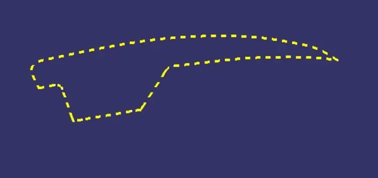
A parting line is an inevitable part of injection molded products. It is the line of separation between where two halves of a mold meet. It manifests itself on injection molded parts as a line that runs the entire perimeter of the part.
For creating parting line I have split class B surface with join of Class A and C.
- CREATION OF CORE AND CAVITY BLOCK -
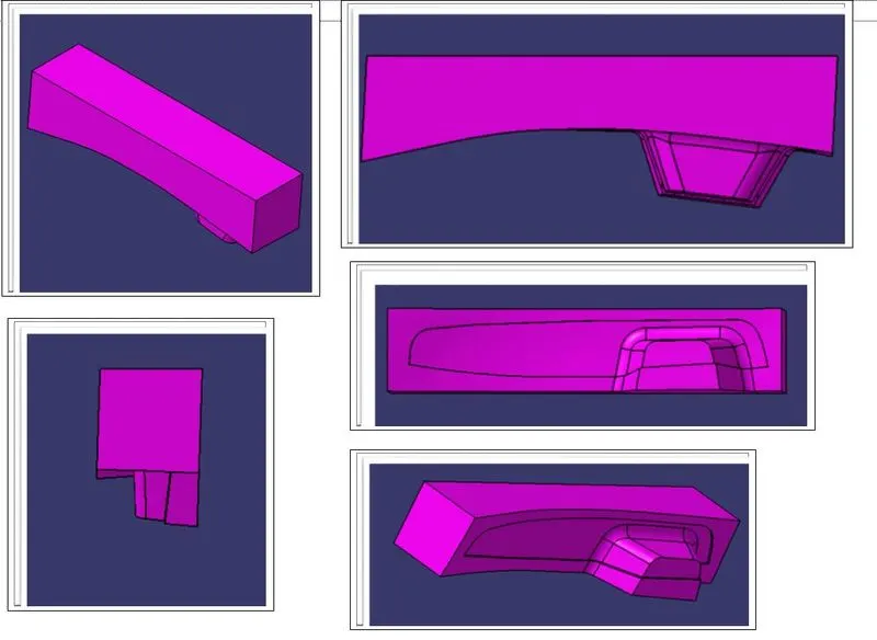
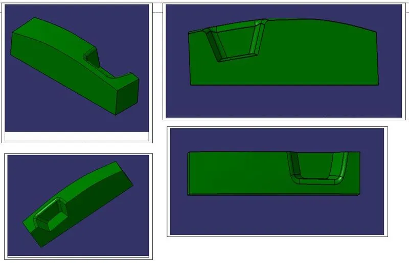
For creating core and cavity block , first I have extruded a reactangular block. Then after trimming this rectangular block with parting surface with component we get core block. And after trimming this rectangular block with class B surface we get cavity block.
The following image shows core block in various orientation.
The following image shows cavity block in various orientation.
The following image shows the core-cavity block with parting line , parting surface , component and tooling axis.