Week 8 - Challenge 6 - Core & Cavity Design
CORE AND CAVITY DESIGN
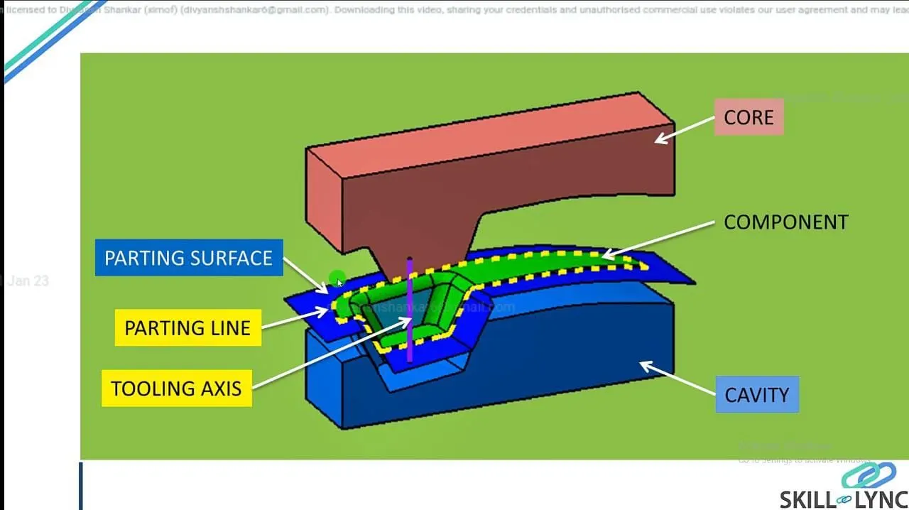
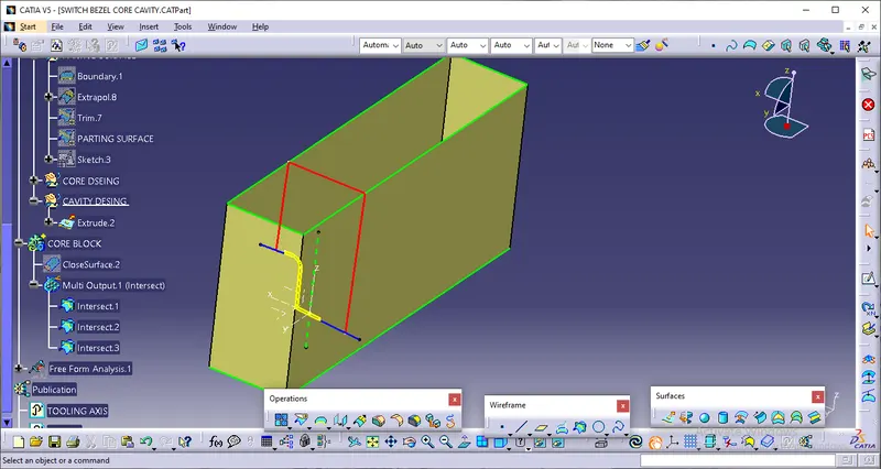
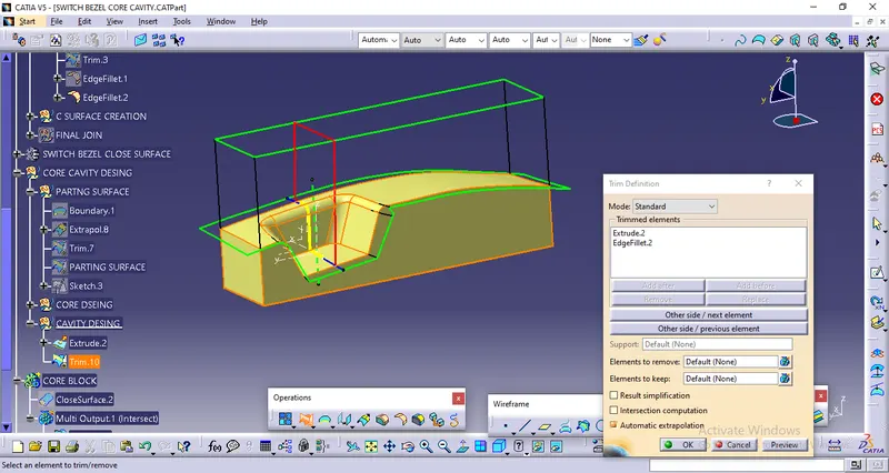
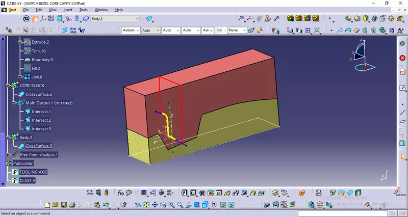
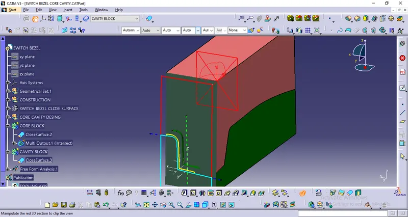
AIM: To Create the Core and cavity blocks for the switch bezel component.
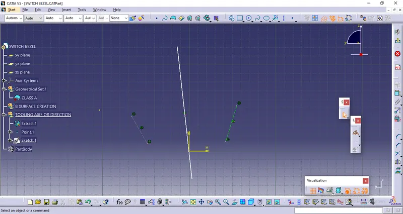
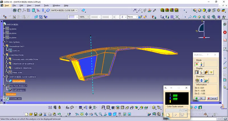
TOOLING AXIS : It is nothing but the direction in which the mold opens and closes the draft angle needed to be provided by considering this tooling axis. We can create a tooling axis by using the bisecting method.
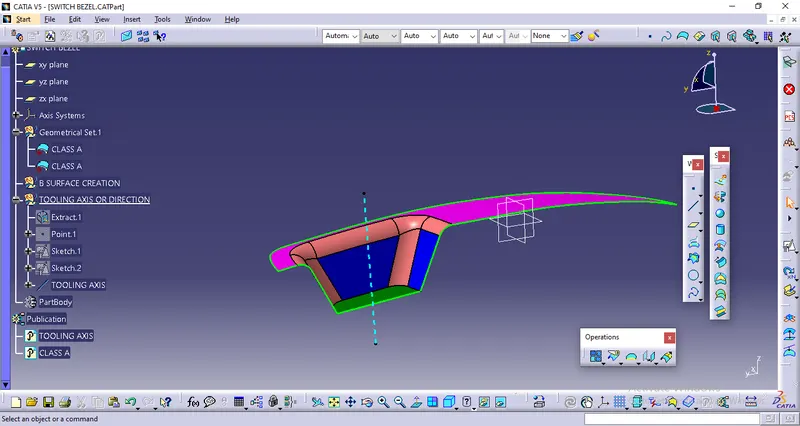
DRAFT ANALYS The Draft Analysis command enables you to detect if the part you drafted will be easily removed. This type of analysis is performed based on color ranges identifying zones on the analyzed element where the deviation from the draft direction at any point, corresponds to specified values.
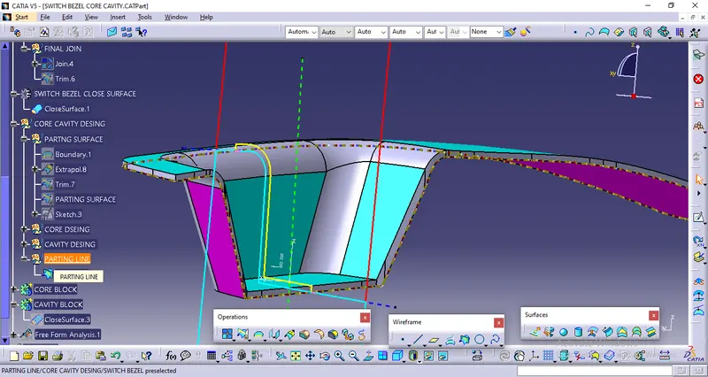
PARTING LINE
- A parting line is an inevitable part of injection molded products.
- It is the line of separation between where two halves of a mold meet.
- It manifests itself on injection molded parts as a line that runs the entire perimeter of the part.
- In most parts, it is just a line that runs straight down the middle.
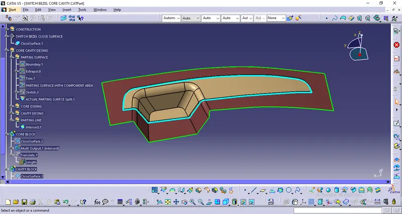
PARTING SURFACE: Generally injection mold has two major components : the movable half and the fixed half, during the injecction molding process, these two halves are pressed tightly from a sealed hollow to avoid the melt flow leakage and maintain certain holding pressure, the pressed surface are called parting surface , usually parting surface are the biggest projection outline of the part.
Core & Cavity Design:
Core - A portion of the mold that goes inside a cavity to form the interior of a hollow part.
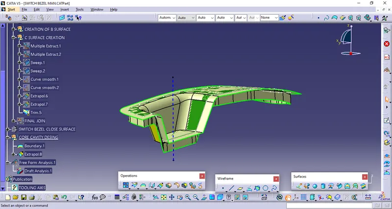
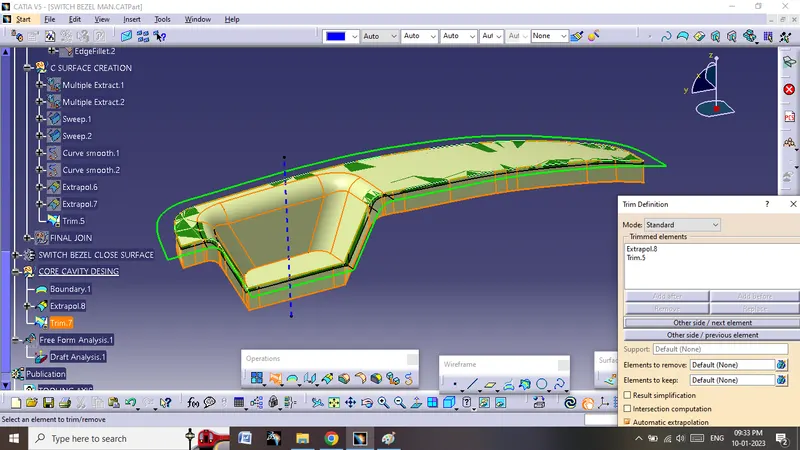
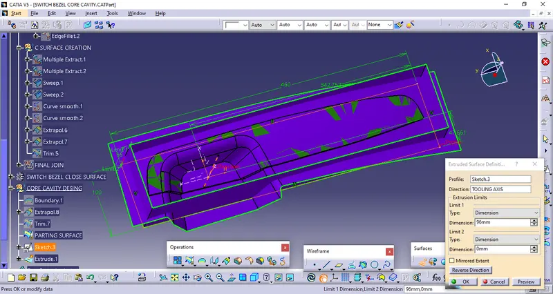
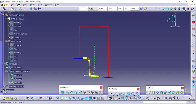
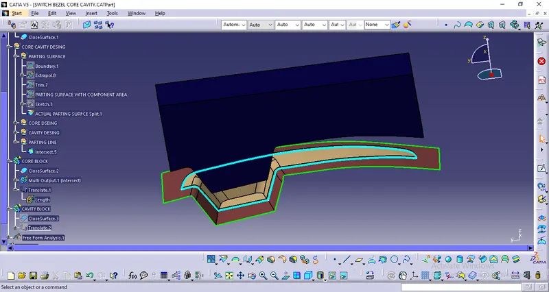
CAVITY DESIGN: A mold is a hollow form typically made from stainless steel that has plastic injected into it to manufacture a plastic part.The plastic is inserted into the mold cavity, which is a hole in the mold shaped like the desired part.
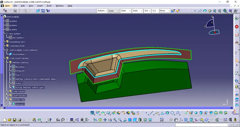
3D VIEWS
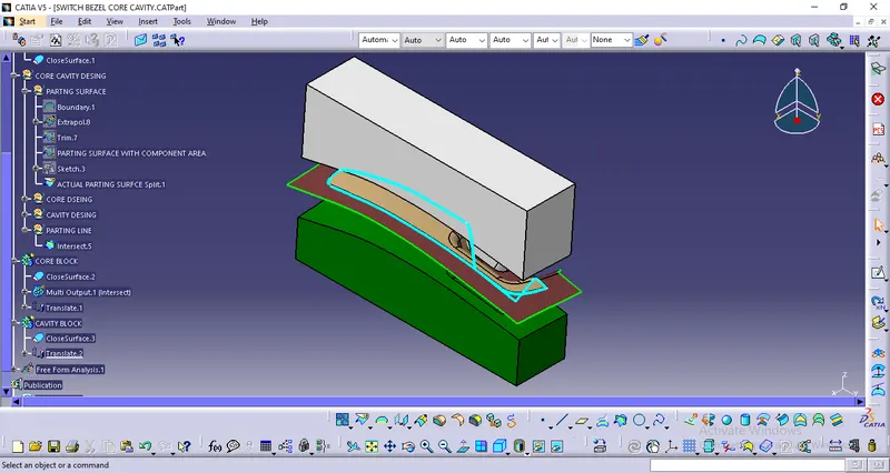
01) ISOMETRIC VIEW:
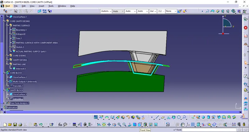
02) FRONT VIEW:
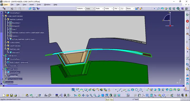
03) BACK VIEW:
FINAL
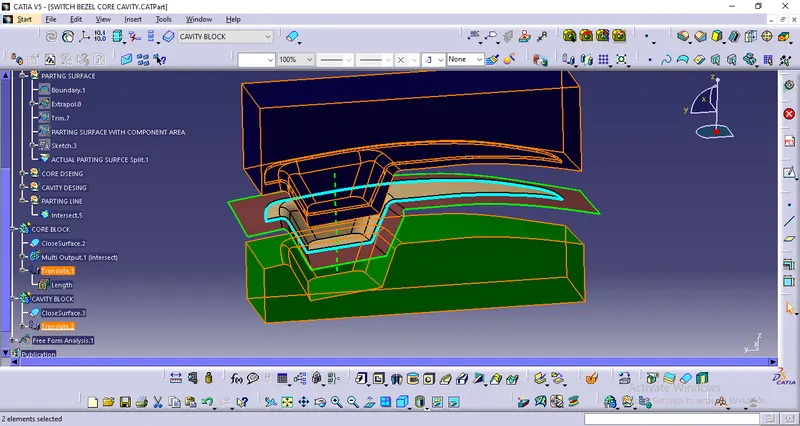
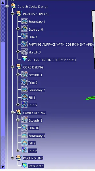
Tree Structure: