Week 8 - Challenge 6 - Core & Cavity Design
Core and Cavirty Design REPORT:
1) tooling axis:
a) Extraceted 1. the base portion that is multiple extract 1.
b) created a point on middle of base using point on surface.
c)used intersect 3D element to intersect class A surface.
d)drawn line intersected class a SURFACE. line 1&2 and projected the created point.
e)took the sketch 2 and created the verticle line. for creation of tooling axis.
f) done publication for tooling axis.
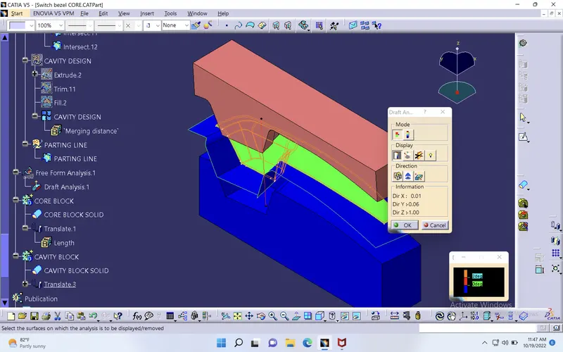
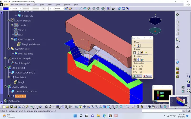
2) DRAFT ANALYSIS FOR CLASS A SURFACE DONE in material mode with draft angle 2 degree.
3)PARTING SURFACE:
a) its a surface that separates the the mould block into 2 blocks core & cavity.
b) class A surface got extrapolated 14 & 15 then Trimmed TRIM 7 with join 2 i.e,(classA & C surface) with Class B.
c) created a boundary to check whether its a single domain or not.
d) created a rectangular positioned sketch for Extrusion. i.e, Extrude 1.
4)CORE DESIGN:
a) sketch 5 extrudedto both the limits 1& 2. and fillied it to the upper portion .1
b) joined the extrude 1 & fill1 .1
c) created the solid core block using the closed surface tool in a new body.
d) created a MULTI OUTPUT Intersect.
i) intersect 9,10,11,12. with first element as a AXIS SYSTEM /ZX PLANE & second element as a CORE SOLIUD BLOCK, PARTING SURFACE, CLOSE SURFACE.2, CAVITY SOLID BLOCK.
5) CAVITY DESIGN:
a) Extrude 2. extrude to negative direction with tooling axis direction.
b) trimmed 11. WITH CLASS B & extrude 2. to the required shape.
c)`& filled 2. the bottom portion and joined the trim 11. and fill 2.
d) created the solid cavity block.
6)PARTING LINE:
a) intersected first element as JOIN 2. & second element as Class B surface.
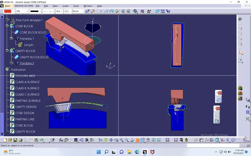
7)translated 1&3 both cavity and core blocks .
8) PUBLICATION FOR CAVITY AND CORE SOLID AND SURFACE BLOCK, TOOLING AXIS, PARTING LINE AND SURFACE, A,B, &C SUFACE DONE.