Week 8 - Challenge 6 - Core & Cavity Design
BEZEL COMPONENT
DEVELOPMENT OF CORE AND CAVITY BLOCKS
Introduction :
This report is on Design and development of Core and Cavity of the Switch Bezel component. Also, the tooling axis and draft analysis of the component was also done.
Core and Cavity Design:
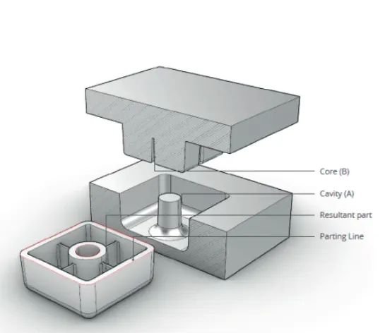
The core and cavity are the two halves of the mold where the hot molten plastic material is injected into the core and cavity and the gap between the core and cavity is filled with the hot molten material during the injection molding process and then hardened into the final shape.
The mold design of the core and cavity is critical to the proper molding of the product. The core is the raised part of the mold and the cavity is the recessed part of the mold.
Draft analysis of the component:
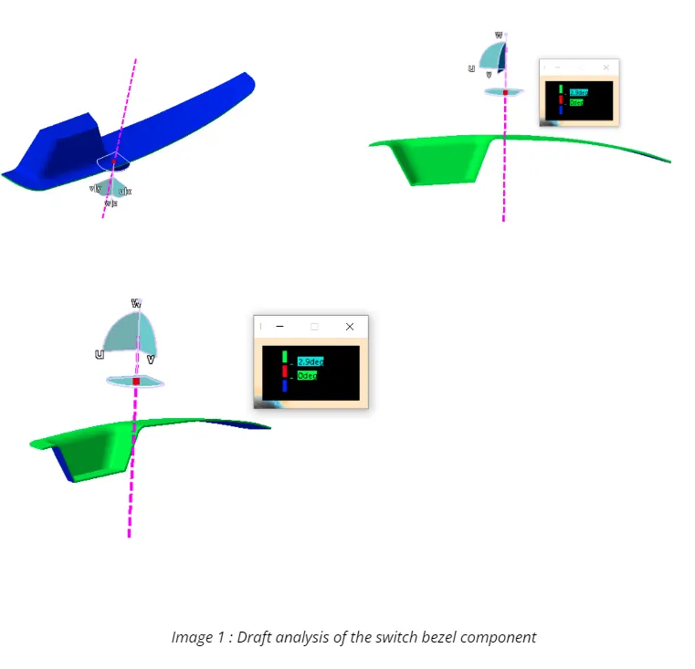
The draft analysis of the component was done since during the design of Bezel, the Tooling axis was already created.
The Tooling axis was created during the development of the component based on the procedures mentioned in that challenge.
The Draft analysis based on the current tooling axis showed that it is the correct axis and all the areas were cleared and the part was feasible to be molded.(See Image 1)
Creation of Parting surface :
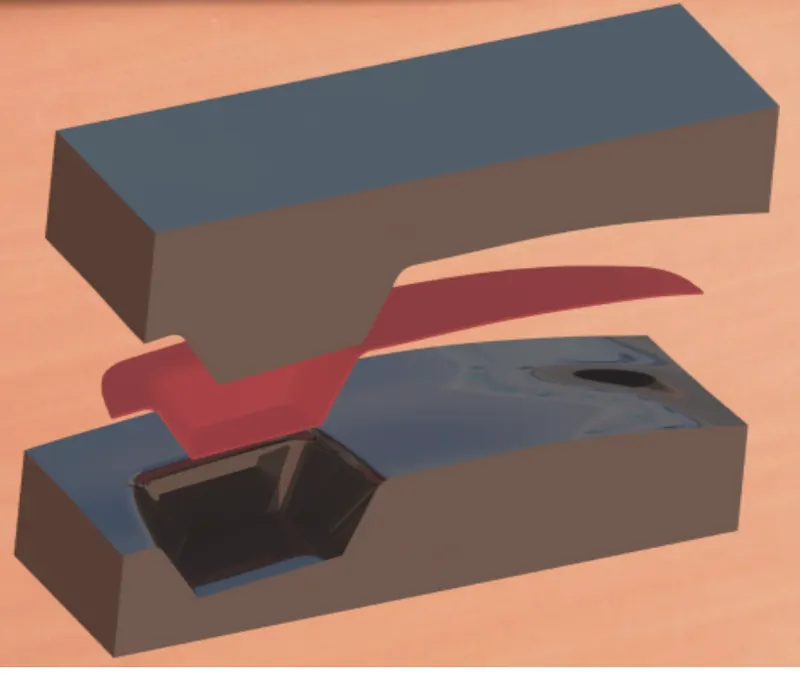
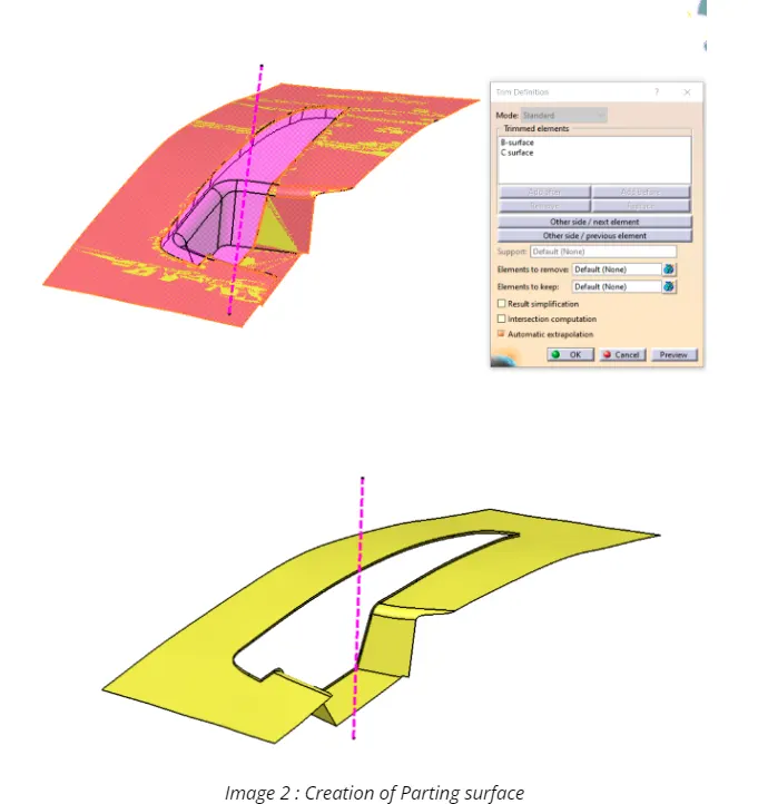
Based on the component and tooling axis, the parting surface was created
as below.
It was decided the thickness of the part will be in the core side as the vice versa might cause an issue due to flash defect.
So the B surface was extrapolated and trimmed with the C surface which created the parting surface required.(See Image 2)
Creation of Parting line :
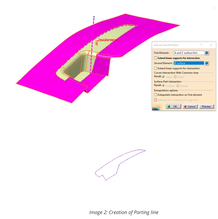
Now the outer surface or the B surface matched with the parting surface and formed the outer area which will be in contact with the cavity.
The intersection of the Parting surface and the component will form the parting line.
So the extrapolated A surface was trimmed with C surface and “intersect” was done between this trim and parting surface creating the parting line.(See Image 2)
Core Block Design:
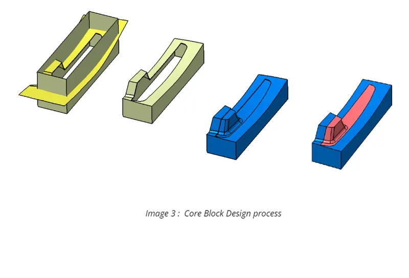
An extrude is done in the shape of a rectangle based on the outer size of the component for the Core block and trimmed with the parting line.
This trim is again trimmed with the A surface which created the core block of the component.
The trim is closed and made a solid body which completes the core design for the component. (See Image 3)
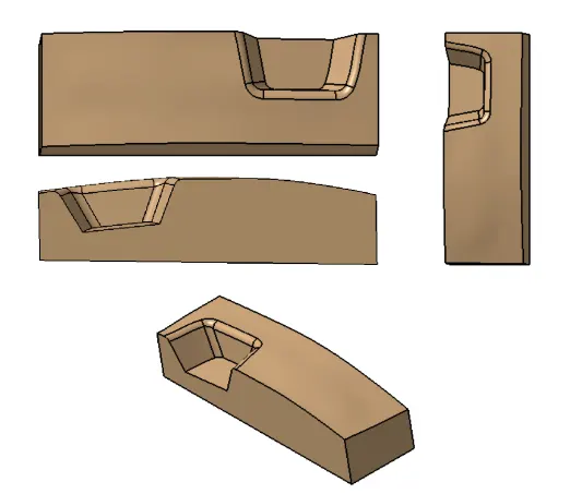
Core Block in different views
Cavity Block Design:
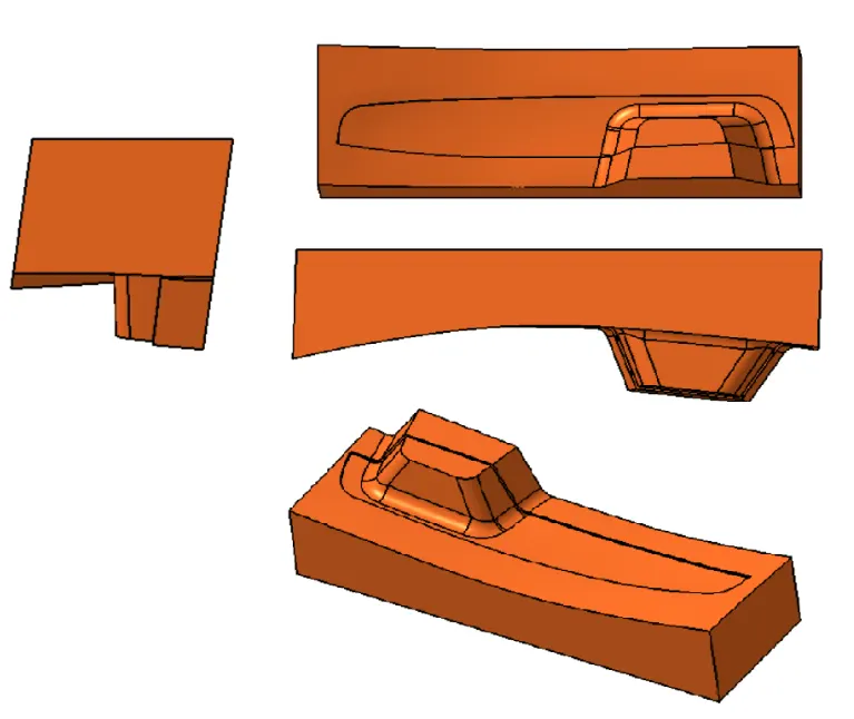
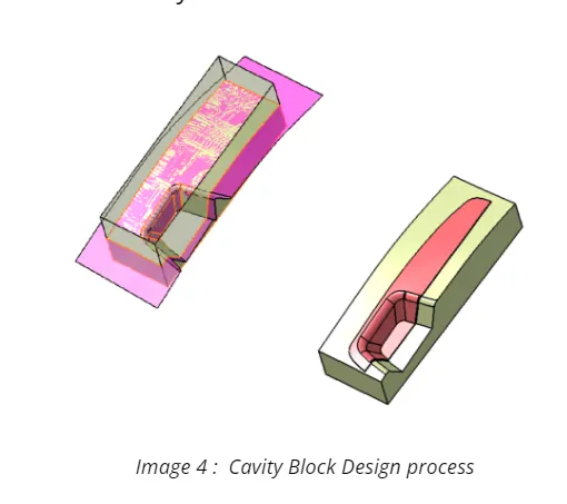
Since the Outer area of the component was matching with B surface, the Extrude created earlier was trimmed with B surface and the open end was closed and made a solid body.(See Image 4)
Cavity Block - Different orientations :